2015 MDOT/ACEC Partnering Conference. Bridge/Structure Construction Update
|
|
|
- Bethany Stevenson
- 5 years ago
- Views:
Transcription
1 2015 MDOT/ACEC Partnering Conference Bridge/Structure Construction Update Corey E. Rogers, P.E. MDOT Bridge Construction Engineer Peter O. Jansson, P.E. MDOT Structures Technical Section Jeremy McDonald, P.E. Fishbeck, Thompson, Carr & Huber, Inc Matthew J. Chynoweth, P.E. MDOT Engineer of Bridge Field Services February 5, 2015
2 Bridge/Structure Construction Update Outline: Articulating concrete block Concrete surface coating warranty Bridge deck construction BOHIM 7 day continuous wet cure errata and advisory Complex structural erection special provision Rigid concrete overlay changes Concrete Grade DM deployment Local agency/mdot/fhwa funding on projects Water blasting steel beams Sign Structure installation inspection Adhesive anchors into concrete Sleeper and approach slab revisions Slab and screed guidance

3 Articulating Concrete Block (ACB)

4 Articulating Concrete Block (ACB) Can be constructed in the wet. 3-4 of water ideal Flow diversion and plume management are concerns Soil borings in river for clay layer identification Mattresses for deeper applications.

5 ACB Mattress


6 ACB Mattress Variable length Within 2 -no grout required at longitudinal joints Always grout transverse joints.
7 Warranties Thin epoxy overlays (5 year) 2 projects in Bay Region Bids were on par with non-warranty projects Contractor innovation with material freedom Concrete surface coatings (2 year) Ensure sound prep Selection criteria developed to be used for projects greater than 500 square yards Eliminates the QPL, establishes parameters and fosters material innovation

8 Bridge Deck Construction BOHIM update
9 Bridge Deck Construction BOHIM update Pour sequences Bridge deck haunches Changing night casting to day casting $2 credit is back QA/QC process for non-pwl bridge deck applications Texturing and curing Exceptions to 2 hour covering rule in cooler temps. Colder weather protection clarification. Form 0395 Bridge Deck Construction Inspection Checklist - Fillable
10 Bridge Deck Wet Cure Advisory N.2 Do not discontinue wet cure nor cast succeeding portions onto the bridge deck prior to completion of the 7-day twophase continuous wet cure. Ensure excess or ponding water is removed prior to casting of succeeding structure portions H.1 (Proposed) Do not cast sidewalk, curb, or barrier pours until the deck concrete attains at least the minimum specified 7-day flexural or compressive strength, and after completion of the 7-day continuous wet cure., The forming of succeeding portions may occur, provided the wet cure is maintained properly.
11 Bridge Deck Wet Cure Advisory Requires the 7 day wet cure, period. Defines two-phase continuous wet cure. Clarifies heavy equipment allowance prior to 7 day cure.
12 Complex Erection Special Provision What does AASHTO consider complex erection? Any one lift using two or more cranes Continuous spans over water or active railroads/rapid transit tracks Erection with floating equipment Phased construction of continuous spans or spans > 200 requiring lane closures combined with active lanes Girders with horizontal curvature and at least 1 of the following: Skew angle greater than 30 degrees Span < 200, radius of curvature < 1100 Span between 200 and 250, radius of curvature < 1200 Span > 250, radius of curvature < 1500 Field-assembled suspension, cable-stayed, truss or tied arch spans Steel girders containing more than one field splice per span
13 Complex Erection Special Provision What triggers use in MDOT projects? Curved steel girders Long spans continuous over multiple supports Working on Bridge Design Manual language to assist designs as to when to use the revised SP.

14 Complex Erection Special Provision
15 Complex Erection Special Provision New Special Provision Defines Falsework, Temporary Support, Primary Member and Secondary Member. Clarifies submittal requirements. Erection Plan Foundation Support Plan Construction considerations. Settlement Crane placement Pick Points Wind Loading Falsework Stability Etc.
16 Rigid Bridge Deck Overlays Three options for rigid overlay materials Latex Modified Concrete Silica Fume Modified Concrete Grade D with Slag Cement

17 Rigid Bridge Deck Overlays Deck overlays with design indicating 2/3 or more of deck surface to be 4 or greater in thickness will be designed for the Grade D with 25-40% slag cement replacement Overlay not to become less than 2 Additional hand chipping may be necessary SFMC overlays were getting too thick Concern regarding cracking Grade D with slag cement proven option
18 Grade DM Concrete for Bridge Decks Recently used on I-96 in Metro, M-231, US-131 over Muskegon corbels, with promising results Expect further use on all MDOT owned bridge deck projects Mix contains optimized aggregate blend, with slag cement replacing traditional cementitious materials up to a certain percent Gaining national popularity in terms of durability, shrinkage crack reduction and low permeability Keep Bridge Field Services aware of issues with placement, pumping, batching, etc.
19 Local Agency/MDOT/FHWA Funding on Projects If you run into unforeseen extras on Local projects need to know funding source and restrictions. Review the agreement between MDOT and the Local Agency. Know the source and if funding is capped, and how to determine if any extra is eligible or will be 100% Local costs.

20 Local Agency/MDOT/FHWA Funding on Projects Some example agreement Language:


21 Local Agency/MDOT/FHWA Funding on Projects Some example agreement Language:
22 Local Agency/MDOT/FHWA Funding on Projects Some example extras: Large quantity of contaminated non hazardous material. Estimated additional costs over $100K Small underground storage tank discovered. Estimated additional costs of $10K. Which cost agreement do you have?
23 Local Agency/MDOT/FHWA Funding on Projects Make sure your client knows and understands cost agreement Work with TSC and MDOT LAP on eligibility of any extra item. (knowing still that funding may be capped)

24 Water Blasting Steel Beams Existing Structure

25 Water Blasting Steel Beams Flood of 2013

26 Water Blasting Steel Beams Containment for water blasting and painting, no sand blasting

27 Water Blasting Steel Beams

28 Water Blasting Steel Beams Spot repairs by hand tool or small power tool, then spot primer See small issue?

29 Water Blasting Steel Beams

30 Water Blasting Steel Beams


31 Water Blasting Steel Beams

32 Water Blasting Steel Beams


33 Sign and Lighting Support Structures Adhesive Anchor Systems
34 Support Structures for Cantilever Signs Traffic Signal Mast Arms High Mast Luminaires Lighting Structures Frangible Non-frangible Dynamic Message Signs Bridge Mounted Signs Truss Signs Strain Poles
35 12SP810(A) Frequently Used SP for Anchor Bolt Inspection and Reporting and Payment Schedule for Overhead Support Structures Inspection During Construction Contractor QC Inspector QA Final Inspection Contractor notifies the Engineer Engineer notifies Structural Fabrication Biennial Inspection Cantilevers TS Mast Arms Tower Lights Others???
36 12SP810(A) Reporting Structural Fabrication notifies Engineer Final inspection acceptable Corrections necessary Payment Repeat final inspection and reporting steps Third final inspection triggers price adjustment Initial: $$$ = 60% of the contract value for work associated with structure and foundation Final: $$ = 40% only upon acceptable final inspection per Structural Fabrication Investigating revisions for more timely response to field, and percentages of payments

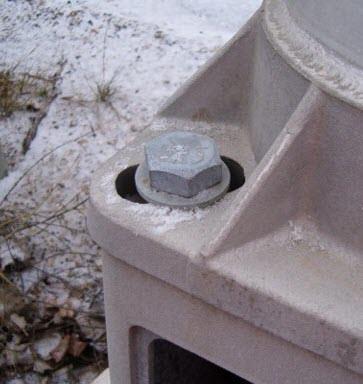

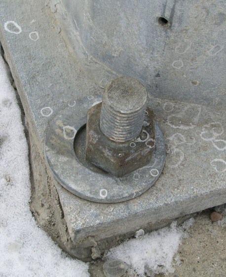


37 Foundation and Anchor Bolt Issues


38 Nut Covers = Corrosion
39 High Strength Bolts MUST be Tensioned using Turn of Nut (TON) Biennial Inspections Dozens of cantilevers with loose bolts all eight bolts at the top arm to upright connection are loose. Lock washers provide additional insurance Not in place of TON
40 40% Holdback


41 Bridge Mounted Signs Improper bolt holes Edge distance violations Misalignment


42
43 Adhesive Anchoring Systems Product Tools Installation procedures Testing J MDOT Std. Spec. for Const. QPL
44 Uses Widening bridges Replacing bridge barrier on an existing deck Attaching bridge mounted signs Installing bridge bearing anchor bolts Lane ties and concrete pavement anchoring.
45 Variety of Systems Two part epoxies, capsules, methacrylates, cementitious grouts Viscosity Cure times All systems are extremely dependent on installation
46 Follow Manufacturer s Instructions Except when conflicting with MDOT Specs. 50 deg. F and rising (ambient and concrete) Holes must be clean and dry Embedment must be 9 diameters for threaded rod and 12 diameters for reinforcing steel Overhead installation is prohibited Should we be installing anchors overhead, underwater, in freezing temperatures??
47 Testing Proof testing Contractor installs, MDOT tests 125% F y 1/16 (0.625) inch slip Install in a separate concrete block Verifies product is still viable Verifies contractor can install successfully Field testing Contractor installs, MDOT randomly selects, Contractor tests 90% F y with 1/16 (0.625) inch slip Test anchors installed in the permanent structure MDOT may test additional anchors Verifies Contractor is installing correctly during production

48 Testing Anchor system failure modes: Steel yield Concrete break out Bond failure

49 Testing Set-up
50 Order of Installation and Inspection System is on the QPL, stored correctly and not expired Proof testing per MDOT specs. Manufacturer required equipment is used Pachometer or GPR is used to locate steel Holes drilled the proper diameter and depth Holes are cleaned per Manufacturer and MDOT specs. Ambient and concrete temp. is 50 deg. F and rising Adhesive is properly mixed and installed with the Manufacturer s required equipment gun, nozzle Adhesive is allowed to set undisturbed during curing (Manufacturer s recommended time is a MINIMUM) Field testing per MDOT specs.

51 Moratorium on Sustained Tensile Loading


52 Questions???
53 Bridge Approach and Sleeper Slab Revisions BDG modified: Normal section 1 on 6 starts 30 from reference line to ensure approach slab and sleeper slab are within structure backfill section Agg base or OGDC section supporting approach slab and sleeper slab is more substantial Agg base to be compacted to 98% Geotextile separator used when OGDC is used to prevent mixing with structure backfill

54 Bridge Approach and Sleeper Slab Revisions BDG A modified: Top rebar no longer continuous from deck into approach. Bottom rebar now continuous. Agg base or OGDC section supporting approach slab and sleeper slab is more substantial Construction joint at backwall to be sawed within 24 hours of deck pour Wheeled or roller based compaction equipment not allowed within 10 of sleeper slab once cast
55 Bridge Approach and Sleeper Slab Revisions Added B: For use on bridge skews greater than 30 degrees Helps to eliminate racking forces on approach slab
56 Bridge Approach and Sleeper Slab Revisions Added C: For use on bridge skews less than 30 degrees
57 Bridge Approach and Sleeper Slab Revisions BDG B modified: Agg base or OGDC section supporting approach slab and sleeper slab is more substantial Construction joint at backwall to be sawed within 24 hours of deck pour Wheeled or roller based compaction equipment not allowed within 10 of sleeper slab once cast
58 Slab and Screed Guidance Provide clarification on how beam cambers are fabricated/calculated for steel and concrete beams Describe effect of change in f c on beam camber Discuss stages of deflection, and establish communication protocol between field office and designer
59 Slab and Screed Guidance Proposing new standard notes: Create note : ONCE BEAMS ARE ERECTED ON SUPPORTS, THE CONTRACTOR IS TO TAKE SURVEY ELEVATIONS OF THE TOP OF BEAMS AT THE SAME INTERVAL AS THE BOTTOM OF SLAB ELEVATIONS SHOWN ON THIS SHEET. THE CONTRACTOR IS TO SUBMIT THE TOP OF BEAM ELEVATIONS TO THE ENGINEER FOR REVIEW AND APPROVAL FIVE (5) BUSINESS DAYS PRIOR TO FORMING THE BOTTOM OF SLAB, OR PAN DECKING INSTALLATION. Create note : THE CALCULATED STAGES OF DEFLECTION ARE AS FOLLOWS: BEAM DEAD LOAD = XX INCHES FORMS AND REBAR = XX INCHES DECK DEAD LOAD = XX INCHES BARRIER AND SIDEWALK = XX INCHES

60 Thank You Questions?