Annex Q Potlatch Corporation Water Intake Modification Plan
|
|
|
- Garry Taylor
- 5 years ago
- Views:
Transcription
1 Annex Q Potlatch Corporation Water Intake Modification Plan Figure Q1 Figure Q2 Site Plans Johnson Screen Installations H:\WP\1346\Appendices\FEIS\D - Drawdown\CamRdy\App_D.doc
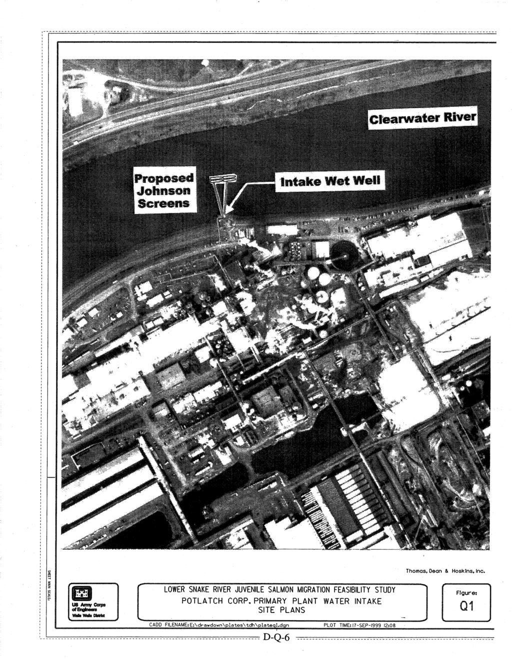
2 Annex Q: Potlatch Corporation Water Intake Modification Plan Q.1 General The concepts and costs for this water intake modification plan derive from a separate report prepared for the Corps by Thomas, Dean & Hoskins, Inc., titled Snake River Drawdown Feasibility Study for: Primary Plant Water Intake Potlatch Corporation (TDH, 1998a). Modifications described here are not considered as part of the project implementation costs. The plan and costs were developed for economic evaluations of local, regional and national impacts. The Lewiston, Idaho, division of Potlatch Corporation imports wood and wood byproducts (wood chips) and manufactures and supplies wood, paper, and consumer products to the Northwest. The Clearwater River, which also forms part of the upper end of the Lower Granite Reservoir, supplies all water to the plant. There are currently two independent water intake structures at Potlatch located in the reservoir portion of the Clearwater River: 1. The primary plant water intake. 2. An experimental fish hatchery intake (currently unused). Potlatch is mainly concerned with the impact of the possible drawdown of the lower Snake River reservoirs on the primary plant water intake. Consequently, this study team examined only the need to improve the primary intake structure. The principal effect of drawdown on the existing system would be a decrease in the low-water water surface elevation. The primary plant water intake consists of the following: 1. A 9-meter (30-foot) deep wet well structure that is a concrete vault roughly 8 meters (25 feet) square, constructed immediately adjacent to the levee along the Clearwater River. 2. The wet well inlet with bar screen inlets located above the bottom of the wet well. When lower stream elevations occur after drawdown, the bar screen inlets would be above the water surface. 3. Traveling screens that provide filtration of large material. 4. Five pumps with 200-horsepower motors located at the top of the vault structure. 5. A 60-millimeter (24-inch) or 762-millimeter (30-inch) supply pipeline to the treatment plant. Based on information from Potlatch Corporation records, the elevation at the bottom of the wet well is approximately 220 meters (723 feet). The lowest elevation along the stream bottom adjacent to the wet well is 219 meters (719 feet). The current operating pool level varies between 223 meters (733 feet) and 228 meters (748 feet). According to Potlatch, the existing water intake system is operating well and serves the facility adequately. One isolated hydrologic event, the January flood of 1996, did affect the facility. During this flood event the extreme river flow deposited enough sediment adjacent to the water intake structure to force a plant shutdown. The condition was temporary, and the plant resumed operation within a week. D-Q-1
3 Improvements outlined in this annex would not be required under current operation, but would be required if the proposed drawdown occurs. Q.2 Standards Q Relevant Codes and Standards Potable water supply is regulated by the U. S. Environmental Protection Agency under the regulations stipulated in Title 40, Chapter I, Subchapter D - Water Programs of the Code of Federal Regulations. Since several endangered species within the Snake and Clearwater rivers might be affected by construction operations, all work within the rivers is also regulated by the National Marine Fisheries Service as stipulated in Title 50 of the Code of Federal Regulations. Q Design Criteria Primary Plant Water Intake Requirements are as follows: Average daily demand: 9 to 12 million liters (35 to 45 million gallons) per day (source: Potlatch) Peak flow: 2.0 m 3 /s (71.3 cfs) (source: Potlatch) Postdrawdown Stream Characteristics are as follows: Minimum stream bottom elevation (adjacent to wet well): 219 meters (719 feet) (source: Potlatch) Low water elevation (at 28 m 3 /s [1,000 cfs]): 222 meters (728.4 feet) (source: Corps) 100-year high water elevation (at 3,682 m 3 /s [130,000 cfs]): 227 meters (744 feet) (source: Corps) Q.3 Intake Modifications Q.3.1 Options Because there are many unknowns concerning the effects of drawdown, such as river high-water elevation and velocity and stream bottom elevations, the options included in this report were selected based on a number of assumptions as well as engineering judgment. The existing water intake structure is shown in Figure Q1. The principal effect of drawdown on the existing system would be a decrease in the low-water elevation. The actual low-water elevation after drawdown would be below the existing wet well bar screen inlet. This study team assumed that the existing wet well structure could be used, and that it is deep enough to collect water from the low stream water condition after drawdown. Two options were considered: 1. Install new bar screens in wet well This option allows operation of the existing intake structure. A new inlet would be cut in the existing wet well, and a new bar screen would be attached. The existing bar screen would be removed and the existing inlet sealed. The primary disadvantage to this option is that significant channel change would be required near the wet well. This channel would be subject to significant sedimentation, requiring regular maintenance. 2. Install new screened inlets in stream channel This is a relatively maintenance-free option. Screened inlets constructed within the natural stream channel would collect water from the Clearwater River and transport the water to the D-Q-2
4 existing wet well via collector pipes. Several types of screened inlets are available. A common inlet structure consists of Johnson Screens constructed on vertical pipe sections that connect to the wet well intake pipes (see Figure Q2). Johnson Screens are continuously slotted screens constructed in a tubular shape. The screens are easy to install, easy to maintain, and are efficient to use (high percentage of open area over total surface area). The study team assumed that Johnson Screens would be used and estimated that three T-54 screens would be required to meet peak plant demand. To allow one screen to be out of operation without affecting performance, one additional screen is recommended. Two screens of the four screens would be constructed on each conductor pipe. This configuration would allow the plant to operate at roughly 70 percent of peak demand should one conductor pipe be removed from service for maintenance. The study team assumed that the foundation conditions would permit the construction of a suitable foundation for the intake screens and that it could be located and protected so that scour would be prevented. Potlatch Corporation uses on-site wells for potable water supply within the plant. Therefore, improvements to the primary plant water intake system would only affect processing operations. Potlatch has indicated that the plant has a permit to use a temporary water intake system that is installed with a crane adjacent to the primary intake when necessary. This temporary system can supply up to 0.5 million liters (2 million gallons) per day. Q.3.2 Construction Methods The study team selected the installation of screened intakes in the stream channel as the most reliable modification. This option is the least susceptible to problems associated with the accumulation of sediments. There are two primary construction methods used for this type of in-water construction. A common method is to surround the construction area with a sheetpile cofferdam system that allows the construction area to be dewatered. The installation of the pipeline and the four screened intakes can take place in relatively dry conditions. After completion of the installation, the sheetpile is removed. This work would most likely proceed after drawdown occurs so the head pressure on the sheetpile and subsequent seepage into the construction area is minimized. This coffercell system, similar to that used for bridge pier construction, is directly applicable to construction of the river intakes. Dewatering of the trench segment presents some stability concerns. The major assumption is that there is sufficient overburden so that driven sheetpile segments remain stable without cross-bracing. Underwater construction could be used only if construction took place before drawdown occurred. This is because stream velocities would be much higher after drawdown, making construction with divers difficult. Work would be staged on a floating work platform using a derrick crane to excavate and place material. Elements would be prefabricated on deck. In-water installation by divers would be minimized. Underwater construction for this installation would create turbidity in the water caused by excavation and backfill of the trench. The study team selected cofferdam construction rather than underwater construction for installation of the screened inlets. The construction method for modifying the Potlatch primary plant water intake system using Johnson Screens is summarized as follows: D-Q-3
5 1. Cofferdams Cofferdams would be constructed around the proposed Johnson Screen locations shown in Figure Q2. Due to the location of the screens in the middle of the river, only one cofferdam installation would be required, and stream flow would be diverted to the north side of the river. Sheetpile cofferdams are proposed. 2. Trench Excavation Trenches would be constructed using open-cut trench methods. Assuming two 1,067-millimeter (42-inch) conductor pipes would be installed, the minimum trench width would be 2 meters (5 feet, 6 inches). It is assumed that the pipe would be installed above 305 millimeters (12 inches) of pipe bedding and that 914 millimeters (36 inches) of cover would be required above the pipe. Therefore, the total trench depth would be 2 meters (7 feet, 6 inches). 3. Pipeline Installation Conductor pipes would be 1,067-millimeter (42-inch) ductile iron. Two conductor pipes are required, each 76 meters (250 feet) in length. Vertical pipe supports for the Johnson Screens would be 1,067-millimeter (42-inch) ductile iron pipe. 4. Air Backwash Piping Conduits for the backwash system would consist of 102-millimeter (4-inch) ductile iron pipes between the pump house (above the wet well) and the Johnson Screens. These conduits would be installed within the conductor pipe trenches. Backwash piping would be installed up to the wet well pump location where they could be accessed for maintenance. A compressor could be brought on site and connected to the piping when screen cleaning is necessary. 5. Trench Backfill Trenches would be backfilled with granular borrow from the top of the pipe bedding to the existing ground surface. Sources for the backfill material are available within the local area, minimizing long haul charges. 6. Johnson Screen Installation The four Johnson Screens are each 1,372-millimeter- (54-inch-) diameter tubular structures. All screens would be installed on 1,067-millimeter (42-inch) vertical pipe supports in line with the river flow. 7. Channel Armor Existing channel slopes and the stream bottom would be stabilized with heavy riprap. The study team estimated that the material size would be between 457 millimeters (18 inches) and 914 millimeters (36 inches) in size (D 50 = 610 millimeters [24 inches]). Riprap would be placed a distance of 30 meters (100 feet) upstream and downstream of each pipeline. The team assumed that riprap would be hauled from a nearby quarry and that some haul costs would be incurred. 8. Remove Cofferdams Once the pipelines and screens were tested and accepted, the sheetpile cofferdams would be removed, and the system placed in service. D-Q-4
6 9. Signage There would need to be signs installed on either side of the river to warn against dropping anchors through this part of the river. This sign would also need to prohibit boats that displace more than 0.6 meter (2 feet) of water from using this river during low stream flow periods of the year. 10. Debris Impact Structure Three piles 4 meters (12 feet) long, driven 1.5 meters (5 feet) into the riverbed would support a high strength grate 3 meters (10 feet) wide and 2 meters (7 feet) high. This structure would protect the Johnson Screens. Q.3.3 Construction Materials 1. Pipe: 1,067-millimeter (42-inch) outside diameter (OD), class 51 ductile iron (wall thickness = 13 millimeter [0.53 inches]) 2. Pipe fittings: Mechanical joints 3. Pipe coating: Cement-mortar interior lining Q.4 Schedule There is no significant variation in process water consumption by the Potlatch plant throughout the year. The ideal time for improvements to the water intake structure would be during an annual plant shutdown. Potlatch recommends that screen and pipe installations be made prior to shutdown. During the shutdown, three days would be available to make connections to the wet well without affecting plant operations. Cofferdams represent a significant portion of the construction cost for the project. The ideal construction window would occur between September and December when stream flows are minimal. This would minimize the size of cofferdam used. D-Q-5
7
8