THE TRENCHLESS TREND. Traditionally, pipeline shore crossings have integrated the by shallow waters, which are typically subject
|
|
|
- Everett Short
- 5 years ago
- Views:
Transcription
1 56
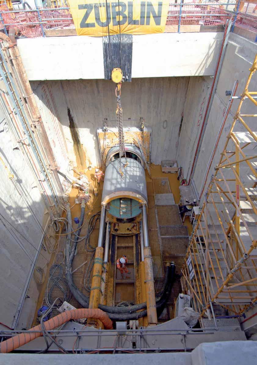
2 THE TRENCHLESS TREND Pipeline shore crossings are often one of the most Costs and risks involved will change with every site, and every complex and technically challenging elements of any project. subsea development. Challenges are compounded Traditionally, pipeline shore crossings have integrated the by shallow waters, which are typically subject open cut and cover method into the design. In this method, to breaking waves, storm surge, and tidal movements. The the pipeline traverses the shoreline within a pre-excavated presence of complex trench which, after pipeline geological features, as well installation, is backfilled as difficult site accessibility can also complicate matters. Close to shore, an emphasis is placed on environmental values and social sensitivity as the development of infrastructure in the coastal environment is often subject to strong public opinion and specific code requirements. Increasingly, trenchless methods are being incorporated into shore crossing designs as an alternative to traditional open cut and cover methods. These can be used to help minimise impact on the coastal environment. Two trenchless shore crossing methods being used with an increased frequency are horizontal directional drilling (HDD) and microtunnelling. Design challenges for a trenchless pipeline shore crossing extend beyond considering pipeline mechanical, stability and cathodic protection (CP) design. Engineers must also tackle the challenges associated with the trenchless methods of HDD or microtunnelling at a coastline and ensure they are suitably integrated with the pipeline design. Every pipeline shore crossing is different and no method is universally suitable. Dean Campbell, Engineering Manager, Atteris Pty Ltd, Australia, discusses the design of trenchless pipeline shore crossings. with an engineered material. While proven and reliable, the method can have a high physical impact and is often not compatible with environmentally sensitive coastlines. Where the shoreline is made up of cliffs, is difficult to access, or when difficult weather patterns and metocean environments are present, the implementation of a trenchless shore crossing can reduce not only the environmental footprint, but also the overall risk, schedule and cost for a project. The emergence of HDD Since the 1980s, the onshore pipeline HDD construction technique has been used for longer, larger and more complex shore crossings. Today, HDD is the most common trenchless shore crossing method employed for small to medium diameter pipelines. HDD for shore crossings involves the pre-drilling of a pilot borehole through the ground from a point onshore along the Figure 1. Advancing a microtunnel at a shore crossing. 57


3 pipeline route, to a suitable location offshore. The borehole is held open with drilling fluid, providing an open conduit for the pipeline to traverse the shoreline. Hole opening or reaming is performed by using the drill rig to push a hole opener forwards along the alignment using the pilot hole as guidance. Forward reaming is the most common method used for shore crossing HDDs. Alternatively, the hole opener can be pulled through the pilot hole from a support barge offshore of the exit point. This method is similar to the commonly used back reaming method used for land-to-land HDDs. Figure 2. HDD set-up for a pipeline shore crossing. A range of pipeline installation techniques are available; however, the most common method is to thrust a pre-fabricated pipeline string into the borehole from an onshore stringing yard. Microtunnelling In the 1990s, shore crossing methods incorporating microtunnelling (a form of pipe jacking), were first adopted by pipeline engineers as a trenchless alternative to HDD. Typically, microtunnels are suited to pipelines where HDD is not feasible due to the large diameter of the pipeline to be installed, or where geotechnical conditions exclude the use of HDD. The tunnel internal diameter for a shore crossing is typically 1.8 to 2 m as a minimum; however, diameters may increase with tunnel length. Microtunnels are formed by thrusting pre-fabricated concrete ring sections (jacking pipes) from an onshore entry shaft along the design profile. Excavation is achieved using a tunnel boring machine (TBM), which is situated at the front of the tunnel. Thrust force is provided at the entry shaft by hydraulic rams which engage the last installed jacking pipe and thrust the tunnel and TBM forward along the alignment. At the completion of a cycle, the rams retract allowing space for subsequent jacking pipes to be installed. After the tunnel has been constructed it is fitted out for pipeline installation. In general, as the tunnel length increases, so too does the complexity of pipeline installation. A common installation method is to pull the pipeline through Figure 3. Pipeline installation at shore crossing by HDD. 58


4 the completed tunnel from a pipelay barge moored offshore using a winch located onshore. The trenchless method selection process For a given project, there may be numerous viable permutations of each shore crossing method. This will lead to the development of a number of options that the pipeline engineer will consider and develop early in the project development cycle. Options will extend beyond those normally considered for a typical land-to-land HDD or microtunnel design. For example, it may be desirable to use microtunnelling to avoid disturbing coastal sand dunes and cliffs. The pipeline engineer may propose tunnelling underneath the sand dunes to meet an open trench on the beach, which will house the Figure 4. Microtunnelling site at a pipeline shore crossing. pipeline through the narrow surf zone. As an alternative, the engineer may also propose that the tunnel is extended so that the tunnel meets the open trench beyond the surf zone. The option that is selected by the project will depend on a number of site specific factors. Continuing the example, the pipeline engineer may establish the presence of a strong, thick limestone cap rock layer offshore, which is not present on the beach. This may make underwater TBM recovery following completion of the tunnel construction difficult. This alone may push the pipeline engineer to opt for a shorter tunnel; however, they may also establish that dredging a trench in the surf zone will be very costly due to onerous sea state or geotechnical conditions. The solution to this problem may be to allow for rock fragmentation, at the tunnel exit point or select a longer tunnel option. The example simplifies an often intricate problem to illustrate the types of constraints that are considered when developing a pipeline shore crossing design method. In reality, the option that is selected will depend on the site specific constraints and the site conditions which have been discussed previously. Constructability of the option is also considered in detail, including fresh water requirements, laydown areas, footprint for pipeline stringing yards, offshore equipment operability, pipelay barge access and seabed dredgability. A process for evaluating the shore crossing methods and their respective permutations is required to select the most suitable option for the chosen landfall site. A suitable process involves considering project costs, risks and project scheduling requirements. The option that will prevail is the one that is best suited to the chosen landfall site from a cost and risk perspective, while meeting the project schedule requirements. This process is usually performed at a pre-feed project level. Engineers should be cautious when executing this process with very limited site data, as the results will be inconclusive. Returning again to the example, the shore crossing selection process may establish that an HDD option is in fact more cost-effective than a microtunnelling option. It may also establish that the option is of equivalent risk while complying with the project schedule requirements. The reality of such a conclusion will always vary between different landfall sites and pipeline projects. The design elements are often co-dependent, and changing one will in turn change how the rest are designed. An example of co-dependency is pipeline stabilisation design and pipeline installation methodology. A standard method for installing pipelines 60


5 Although the concept of drilling exploration HDD pilot holes may be perceived to provide a greater level of confidence, it is not a substitute for a thorough geotechnical drilling campaign and may provide misleading data. This technique of ground investigation is usually also more expensive compared to a conventional geotechnical campaign. Figure 5. A laybarge recovering the pre-installed pipeline string at an HDD site. through microtunnels is by using the shore pull method, where the pipeline is fabricated on a pipelay barge offshore and pulled through the tunnel using a linear winch located onshore. Key design considerations In addition to the standard pipeline design challenges, attention should be focused on the following aspects for a successful trenchless pipeline shore crossing: Geophysical and geotechnical surveys should be performed to support site and method selection. Typically, this will commence with a geophysical survey on a select range of preferred sites. The data should be used to create an inferred geological engineering model, which will be used to plan subsequent geotechnical campaigns, and provide input into the site selection process. The shore crossing design concept should be selected in conjunction with the pipeline landfall site selection and should be chosen on the basis of cost, risk and schedule. This is typically performed at a pre-feed project stage on the basis of preliminary site data. The design of the subsea exit point, where the pipeline transitions from the tunnel or borehole out on the seabed or trench, should be a major focus of the design. Pipeline engineers should ensure the pipeline makes a smooth transition from the borehole or tunnel onto the seabed or trench. This avoids configurations that may cause the pipeline to overstress, freespans to form and potentially fatigue issues. CP design should consider the additional complexities inherent to a trenchless shore crossing. The selection of a pipeline coating and CP system must be compatible with the trenchless method being employed. Constructability of the trenchless shore crossing including pipeline stabilisation, pipeline installation, dredging and TBM recovery should also be considered. Geotechnical surveys Geophysical and geotechnical surveys are usually adequate for providing detailed information. A suite of geophysical investigations, SPTs, CPTs and geotechnical boreholes both onshore and offshore should be carefully planned and executed. An analysis of the seismic refraction data will assist in locating the CPTs and boreholes in the most appropriate locations for the pipeline shore crossing design. Corrosion protection system design Corrosion protection systems for subsea pipelines incorporate an external coating for primary protection and a cathodic protection (CP) system for secondary protection. Regions of transition between wet and dry environments at shore crossings present major technical challenges for corrosion protection design. Intertidal zones create a highly corrosive environment because of the cyclic wetting and drying of the pipeline with each tide. Exposure to air provides a supply of oxygen which aids the corrosion process. Consequently, it is critical that the CP system functions adequately across the intertidal zone. This can be complicated because of the increased electrical resistivity of the ground when it dries at low tide. This can result in insufficient protective potential at the onshore end of the intertidal zone, allowing external corrosion to transpire on sections of the pipeline if coating damage has been sustained. Key issues specific to trenchless pipeline shore crossings include the following: The abrasive nature of pipeline installation has a high risk of corrosion coating and field joint coating damage. External coatings are impractical to inspect and repair under water after installation. CP bracelet anodes are not typically suited for pipelines installed using HDD. Additional anodes maybe required outside the HDD section to ensure the pipeline is protected; i.e., an increased requirement of electrical throw. Increased importance of correct coating selection, including field joint selection and system compatibility to ensure long-term pipeline integrity. Distinct interface between the CP systems between the offshore subsea, HDD or tunnelled section, intertidal zone and onshore environments. Pipeline shore crossings are often one of the most complex and technically challenging elements of a subsea pipeline project. As such, it is important that the design of the pipeline shore crossing and site data collection surveys are prioritised at an early stage in a project. It is important that projects engage independent, competent and experienced engineering companies to ensure the best landfall method is selected and correctly designed for the project. A key advantage for selecting trenchless technology for a pipeline shore crossing is that it avoids impacting environmentally sensitive sites or large obstructions by drilling or tunnelling underneath them. In addition, there can also be project cost and schedule benefits when selecting these methods. 62