Fire & Safety Measures
|
|
|
- Shona Ford
- 5 years ago
- Views:
Transcription
1 FORM1A M/s. Military Engineers Services Fire & Safety Measures Annexure 10 Fire safety is a major cause for concern as buildings are mushrooming in the urban cities. The project is being planned, designed and constructed to ensure adequate fire safety to the property and inhabitants and this shall be carried out, in accordance with Fire Protection of norms of the National Building Code of India. The fire fighting requirements, arrangements and installations required in building shall also conform to the provisions of Fire Protection of National Building Code of India. Fire fighting: One wet riser system for every 1000 Sq.mtrs floor Plate area. Internal fire hydrants strategically located to cover 30Mtrs. Span. One hydrant system. One No. Fire pump, 1 no. Sprinkler pump, 1 no. Jockey pump and 1 no. Diesel driven hydrant/sprinkler pump. in fire pump room Upright sprinklers in Basements-sprinkler to have coverage of Sq.mtrs. (as per local NBC norms). Two-way communication system. External yard hydrants at 45 mtrs center-to-center 2 mtrs from building fascia. Portable fire extinguishers: Water type extinguishers at all staircase landing at entrance One No. CO 2 type extinguisher and sand buckets for every 8 car parks Down-comer pumps. Fire detection and alarm: Addressable microprocessor based fire alarm and detection system Photo-electric type addressable smoke detectors above and below false ceiling spaced as per NFPA standards (500 Sft coverage per detector) Main fire panel to be located in Control room (in Basement) Addressable hooters with strobes, manual call stations (pull down type) at all lift lobbies and staircase entrances. De-energizing of AHU s fire dampers and escalators, initiation of staircase pressurization, grounding of lifts, on signal from fire panel Integration with IBMS and PA systems. Prepared by Sri Sai Manasa Nature Tech Pvt Ltd 1
2
3
4
5 FORM1A M/s. Military Engineers Services Water Balance in KLD Annexure-4 Water is an essential component of the basic infrastructure for urban settlements. Besides domestic use, water is also required for fire fighting and other miscellaneous purposes. The water requirements have been calculated as per IS: Code of basic Requirements for Water Supply, Drainage and Sanitation (4th Revision) by Bureau of Indian Standards (BIS), considering the needs for Indian town and cities. It is expected that the project would generate approx. 379 KLD of wastewater of the total domestic water % of Flushing). The details of water consumption and wastewater generation are shown below: Table: 2.0 Calculations for Daily Water Requirement S.No. Description occupancy demand (lpcd) total requirement in KLD Domestic water requirements 1 Hospital Staff/patients Visitors/ Patients attendants BTD Total 437 say 440 Area l/sqm 2 Greenbelt say 24 KVA lt/kva/hr 3 DG set cooling say 7 lt/t/hr for 8hrs 4 HVAC Say 50 Total water requirement 521 Prepared by Sri Sai Manasa Nature Tech Pvt Ltd 1
6 FORM1A M/s. Military Engineers Services Total fresh water requirement Table: 3.0 Wastewater Calculations 440 KLD Potable (70%) 308 KLD Flushing (30%) 132 KLD Wastewater Generated (80% potable + 100% flushing) 379 KLD The wastewater generated will be treated in the existing E-STP (Electrolytic Sewage Treatment Plant) by adding additional modular structures. FRESH WATER ( 440 KLD) POTABLE WATER (308 KLD) (70% of Domestic 80% WASTEWATER GENERATED ( % FLUSHING (132 KLD) (30% of Domestic 80 % 303 KLD HORTICULTURE (Proposed Site) 28 KLD HORTICULTURE (CAF Area) 268 KLD Fresh water DG Cooling Wastewater Recycled Water 7 KLD Prepared by Sri Sai Manasa Nature Tech Pvt Ltd 2
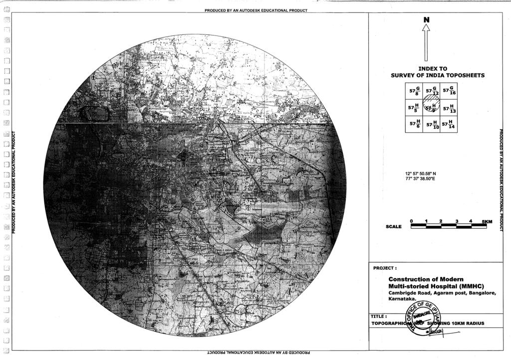
7 FORM1A M/s. Military Engineers Services Rainwater Harvesting Annexure-5 All along the road network of the proposed project, storm water drains would be provided to collect water during rains. They would be adequately sized to prevent flooding of the site. It is proposed to have rainwater harvesting structures for recharge of roof top rainwater and rain water of paved surface at respective apartment. Treatment for silt, oil & grease removal will be provided to rainwater harvesting recharging pit. Overflow from the harvesting pit and storm water of road / open space will be collected through road side storm water drains. For better infiltration of rainwater into ground, storm water drains will be provided with check dams at every 100 m. The storm water drains are connected to nearby natural drain. The details of rainwater harvesting calculation are given in Table below: The rainwater harvesting pits will be provided adjacent apartment blocks, so that the roof water can be directly sent to nearest Rainwater harvesting pit. The excess water if any from the rainwater harvesting pits is diverted to storm water drains. The storm water drains will be acting as recharge trench as the bottom will not be lined and intermittent check dams will be provided in the storm water drains, so that maximum amount of rainwater infiltrate into the ground. The excess water will be diverted into the common storm water drain. Prepared by Sri Sai Manasa Nature Tech Pvt Ltd 1
8 FORM1A M/s. Military Engineers Services Building Materials Details of the Building Material Annexure-6 The building materials chosen for the proposed project are as per the recommendations of the climatic standards. To achieve the maximum energy value, a balance between the availability of building materials locally and skilled labourers will be achieved. The RCC roof is covered with PCC tiles, which reduces the heat penetration by 18%. Prepared by Sri Sai Manasa Nature Tech Pvt Ltd 1
 is a clear glass; it has a microscopically-thin coating of metal")

9 FORM1A M/s. Military Engineers Services Low-e glass Energy Saving-Glass Characteristics/ Low-E Glazing Annexure 7 Low-emission glass (Low-E) is a clear glass; it has a microscopically-thin coating of metal oxide, when the glass leaves the tin bath (at 650 C). This allows the sun's heat and light to pass through the glass into the building. At the same time it blocks heat from leaving the room, reducing heat loss considerably. This is a clear glass which has received, on one of its faces, a silver coating applied by magnetically-enhanced cathodic sputtering. This type of Low-E must be used exclusively in insulating glass, with the coating on an internal face. It can be tempered and laminated. How Low-E Glass Works In the winter, Low-E Glass is designed to work in two ways: First, it transmits the sun's short-wave energy. This means it allows the sun's energy (which provides visible light and invisible heat) in through the windows, which helps heat a home in winter. Second, once the sun's heat is inside a home, the coating works to reduce the amount of heat transferred through the glass to the colder exterior. As a result, less of this heat, as well as the heat produced by a furnace, is transmitted back through the glass to the outside, helping to reduce heating bills in winter. In the summer, heat enters a house through ordinary clear glass to the cooler interior. This happens in two ways: first, through direct short-wave sunlight; and second, by long-wave radiation generated by sidewalks, drive ways, and other elements which have absorbed heat from the sun. Low-E Glass effectively reduces this unwanted radiant heat gain by reflecting a significant portion of long-wave radiation back to the outside, helping to keep homes cooler and reduce cooling costs in summer. Reduction of Heat Loss in winter Low-E Glass reduces heat loss to the cold outdoors by dramatically reducing radiant heat transfer and actually reflecting interior heat back into the room. A Source of Free Energy In addition to its low U-value, Low-E Glass has a high shading coefficient. Compared to other low-e glass products with lower shading coefficients, Low-E Glass allows more of the sun's rays to enter a home as solar energy to be converted into usable heat in winter. Prepared by Sri Sai Manasa Nature Tech Pvt Ltd 1


10 FORM1A M/s. Military Engineers Services Reduced Heat Gain in summer The same effect of keeping interior heat inside in the winter helps reduce the flow of hot outside air into the cooler interior in summer. Lower Utility Bills The bottom line is that Low-E Glass helps reduce the number of heating and cooling BTUs needed to keep a house at a comfortable temperature. That means furnace and air-conditioning systems work less, and that can add up to significant energy savings. Reduction of UV Rays Low-E Glass significantly reduces transmission of the sun's damaging ultraviolet rays, one of the leading causes of premature fading and degradation of fabrics, upholstery and carpeting. Comfort Consumers want comfort and savings. No one enjoys sitting near a cold, drafty window in winter. Low-E Glass works to raise the inside glass surface temperature in winter, to help minimize cold spots and keep homeowners more comfortable. Larger Window Areas Because Low-E Glass is an energy-efficient, high performance glass, architects, builders, and homeowners have the freedom to incorporate larger window and glass areas in their designs, without the resulting excessive energy costs. Appearance Today s Low-E Glass is color-neutral. Homeowners can enjoy the great looks as well as the great performance of windows made with Low-E Glass. Low E Terminology. With Low E, solar selective Low E, hard-coat, soft-coat, sputtered, and pyrolytic terminology to deal with, you need the facts on Low E. Prepared by Sri Sai Manasa Nature Tech Pvt Ltd 2
11
12 FORM1A M/s. Military Engineers Services Thermal Characteristics of Roof External Walls Annexure 9 The thermal characteristics of the building envelope for (a) roof (b) external walls and (c) fenestration considered is given below. Climate considered: Composite Mean Monthly maximum temperature ( C): Above 30 Mean Monthly relative humidity percentage: Above 55 Description Maximum U-factor of the overall assembly (W/m 2 - C) Minimum R-value of insulation alone m 2 - C/W Remarks Roof U R-3.5 Roofs shall comply with either Opaque walls U R-2.35 the maximum assembly U- factor or the minimum insulation R-value The vertical fenestration shall comply with the maximum area weighted U-factor and maximum area weighted Solar Heat Gain Coefficient (SHGC) requirements. Vertical fenestration area is limited to a maximum of 40% of the gross wall area for the prescriptive requirement. The vertical fenestration considered is given below Description Maximum U-factor (W/m 2 - C) Maximum SHGC Remarks Fenestration U Overhangs and /or side fins applied will be considered in determining SHGC for the proposed design The details of the materials used in the project to achieve the above U-values or the R values of the individual components are given below. Material used for construction & its U values S.No Type of construction U values (in W/m 20 C) 1 Brick Plastered both sides 114mm 3.24 Plastered both sides 228 mm 2.44 Concrete, ordinary, dense: plastered both sides 152 mm Kota stone 3 Double glazing 20 mm space 2.67 Prepared by Sri Sai Manasa Nature Tech Pvt Ltd 1
13
14
15
16
17
18
19
20
21
22
23
24