MAXIMO Panel Formwork with One-Sided MX Tie Technology. Product Brochure Issue 08/2017
|
|
|
- Leonard Davis
- 5 years ago
- Views:
Transcription


1 MAXIMO Panel Formwork with One-Sided MX Tie Technology Product Brochure Issue 08/2017
2 Content System Advantages 5 Panel formwork with one-sided MX tie technology Faster Tie Installation 6 The one-sided installation technology with the MX 15 and MX 18 formwork ties 8 Completely without spacer tubes and cones Fewer Ties 10 Optimised arrangement of the tie points Improved Concrete Finish 12 Neat joint and tie arrangement System Overview 14 MAXIMO Panel Formwork at a glance Standard Applications 16 Panel connections, wall connections, T-junctions 17 Corners, wall offsets 18 Stopend Formwork 19 Longitudinal compensation, oblique angles Supplementary System Components 20 Panel heights 300 and Shaft Corner MXSE 22 Tension and Compression Brace 23 Inside Corner MXI 60/60 24 System solutions for fast and safe working Closure Technology 26 Systematic solutions for all applications Issue 08/2017 Publisher PERI GmbH Schalung Gerüst Engineering Rudolf-Diesel-Straße Weißenhorn Deutschland Telefon +49 (0) Telefax +49 (0) info@peri.de
3 Project Examples 30 MAXIMO in use Components 36 MAXIMO MX 15 Important Information All current safety regulations and guidelines applicable in those countries where our products are used must be observed. The photos shown in this brochure feature construction sites in progress. For this reason, safety and anchor details in particular cannot always be considered as conclusive or final. These are subject to the risk assessment carried out by the contractor. In addition, computer graphics are used, which are to be understood as system representations. To ensure a better understanding, these and the detailed illustrations shown have been partially reduced to show certain aspects. The safety installations that may not be shown in these detailed descriptions must nevertheless still be available. Please note that the systems or items shown might not be available in every country. Safety instructions and load specifications are to be strictly observed at all times. Separate structural calculations are required for any deviations from the standard design data. The information contained herein is subject to technical changes in the interests of progress. Errors and typographical mistakes reserved. 3

4


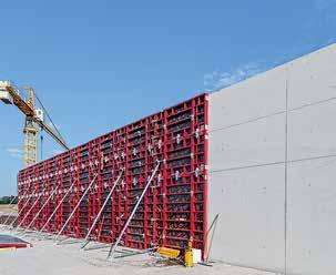
5 System Advantages MAXIMO Panel formwork with one-sided MX tie technology In spite of using fewer site personnel, MAXIMO is significantly faster than conventional panel formwork. One-sided tie installation by just one person reduces costs and also opens up new possibilities for realising visible concrete surfaces using panel formwork. It is fully compatible with the proven TRIO system and fulfils the highest requirements regarding cost-effectiveness and achievable quality of workmanship. All outstanding advantages of the TRIO, e.g. a minimum of different panel sizes and the Alignment Coupler BFD as the only connecting part, were retained in the development of the MAXIMO. Faster tie installation through the one-sided tie technology without spacer tubes and cones. Fewer ties through the optimised tie point arrangement. Improved concrete finish through the neat joint and tie arrangement. 5
 Tie System MX 15 (Permissible load of the tie rod: 90 kn) MX 15 Ties 15 25 for wall thicknesses 15 /")


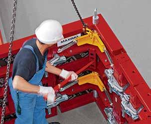
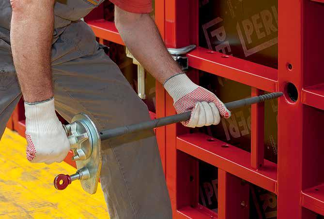
6 System Advantages Faster tie installation The one-sided installation technology with the MX 15 and MX 18 formwork ties Tie System MX 18 (Permissible load of the tie rod: 130 kn) Tie System MX 15 (Permissible load of the tie rod: 90 kn) MX 15 Ties for wall thicknesses 15 / 17.5 / 20 / 22 / 24 / 25 cm MX 15 Ties for wall thicknesses 20 / 22 / 24 / 25 / 30 cm MX 15 Ties for wall thicknesses 30 / 35 / 36 / 40 cm MX 18 Ties for wall thicknesses 15 / 17.5 / 20 / 22 / 24 / 25 cm MX 18 Ties for wall thicknesses 20 / 22 / 24 / 25 / 30 cm MX 18 Ties for wall thicknesses 30 / 35 / 36 / 40 cm MX 18 Ties for wall thicknesses 40 / 45 / 50 cm MX 18 Ties for wall thicknesses 50 / 55 / 60 cm Assembly sequence Unique preparation phase Repetitive tie steps Position the Wingnut MX on the primary formwork panel and tighten the eye bolt. Set out the required wall thickness at the tie by means of a cotter pin, and counter lock with a nut. The usual wall thicknesses are indicated through markings on the tie rod. Push the MX Tie through the closing formwork into the wingnut of the primary formwork and screw in. 6


7 System Advantages 30 cm approx. 3.8 cm As an alternative to the MX tie technology, the conventional DW 15 and DW 20 systems can also be used. Note The programme overview in this brochure features the system components for the use of the Tie MX 15. The corresponding programme overview for the Tie MX 18 is available on request. The opening of the frame allows deviations of the tie rod angle of up to 4. In concrete terms this means an inclined position of up to 3.8 cm for a 30 Panel. As a result, an installation of ties is possible without any problems if, for example, the bottom slab is uneven as is commonly experienced on jobsites. Tighten the MX Tie using the MX Tie Rod Spanner until the ring bolt can be attached. Tighten the ring bolt. Tighten the MX Tie with the MX Tie Rod Spanner as far as the stop position. 7


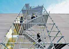
8 System Advantages Faster tie installation Completely without spacer tubes and cones The conical tie rod requires no spacer tubes and cones. This allows tie operations on the side of the closing formwork. As a result, only one person is needed; apart from this, guardrails are not necessary at intermediate levels on the primary formwork. In addition, the required working space between the primary formwork and, for example, adjacent buildings or sheet piling, is considerably reduced. In comparison, two men and significantly more working steps are required when using conventional panel formwork: close unused tie holes screw Wingnut Counterplate onto the DW Tie Rod insert tie attach Cone 1 cut spacer tube to size slide on spacer tube attach Cone 2 insert tie screw Wingnut Counterplate onto the DW Tie Rod secure Wingnut Counterplate with a hammer The MX Removable Sealing The MX Removable Sealing used with the MAXIMO system reliably closes the tie point when using the MX Tie and, thus, prevents any concrete bleeding. This also applies with an inclined tie position of up to 4. In addition, the tie hole is protected by a metal ring against all impacts. Exchanging the removable sealing from MX to MX 18. This can be carried out easily and quickly on the construction site. 8

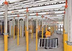
9 Working scaffold is not required Due to the fact that ties are installed from one side only, additional safety measures, e.g. working scaffold on the primary formwork, are not required, which saves both time and money. This is of great importance particularly for higher positioned formwork.


10 System Advantages Fewer ties Optimised arrangement of the tie points With MAXIMO, the tie points on all panel sizes are arranged centrally. Every tie hole is used, and edge ties are not required. There are no unused tie points that have to be closed. This eliminates possible sources of error and reworking at tie points affected by concrete bleeding. At the same time, tie points with MAXIMO are reduced by up to 40 %. This has - apart from the time advantages due to the one-sided MX tie technology - a positive impact on the performance factor. Panel grid arrangement 30 cm MAXIMO panels are available in 6 heights from 30 cm up to 3.30 m, as well as 5 widths from 30 cm to 2.40 m in 30-cm increments. In addition, a 45-cm-wide panel is available that greatly reduces the use of filler plates. Panel connections with Alignment Coupler BFD The Alignment Coupler BFD ensures tight panel joints resulting in an excellent concrete finish. With only one component, every panel connection is flush, aligned and tight. 10


11 System Advantages Width Height

12 System Advantages Improved concrete finish Neat joint and tie arrangement Creating concrete surfaces: systematically, cost-effectively, easily. Realising special wall surfaces with very little extra effort using an efficient panel formwork system is a frequent request of clients and architects. The centrally-arranged tie points in the MAXIMO panel formwork result in a regular joint pattern - horizontally and vertically. Various panel combinations can be selected, opening up a range of flexible design options - which can be realised very cost-effectively. The clearly defined arrangement of the individual MAXIMO panels in so-called MX grids facilitates the visually appealing design of concrete surfaces with a clean concrete finish, no impressions created by unused tie points and free of concrete bleeding at unsealed tie points. Concrete surface design with the MX grid arrangement The defined arrangement of individual MAXIMO panels in a so-called MX grid facilitates the creation of attractively-designed visible concrete finishes. The number and position of the tie points is constant in the variants shown here. 12

13

14 System Overview MAXIMO Panel Formwork at a Glance 14


15 System Overview The following pages describe standard applications for the forming of walls, foundations and corners. The explanations show important basic principles but do not make any claims regarding completeness. All detailed specifications, as well as any possible country-specific data, can be found in the Instructions for Assembly and Use. Furthermore, the corresponding Instructions for Use must also be observed. 15
16 Standard Applications Panel Connections, Wall Connections, T-Junctions Panel connections Wall connections Alignment Coupler BFD Item no T-junctions T-junctions Wall thicknesses cm Internal formwork Inside Corner MXI 50/20 3 x Alignment Coupler BFD 60 MXI 50/ /5 MXI 50/ External formwork Panel MX 60 2 x Alignment Coupler BFD Adapting to the wall thickness with Wall Thickness Compensator MX or timber. 3 x Alignment Coupler BFD MXI 50/20 MXI 50/20 MXI 50/ MXI 50/20 MXI 50/20 MXI 50/
17 Standard Applications Corners, Wall Offsets Corners Corners with MXI 50/20 Wall thicknesses cm Internal formwork Inside Corner MXI 50/20 3 x Alignment Coupler BFD External formwork Outside Corner MXA 45 Panel MX 30 4 x Alignment Coupler BFD MXA / 45 / 30 MXA / 45 / 30 MXA / 45 / / 45 / / 45 / / 45 / 30 MXI 50/20 MXI 50/20 MXI 50/ /25 30 No tie is required on the short side of the Internal Corner MXI 50/20. Wall offsets 30 MXA MXI 50/20 MXI 50/20 MXI 50/20 MXI 50/ MXA cm Inside Corner MXI 50/20 Panel MX 45 Compensation Waler MAR 170 Compensation Waler MAR 85 filler timber supplied by contractor cm Inside Corner MXI 50/20 Outside Corner MXA 45 Panel MX 30 Compensation Waler MAR 170 with 1 Hook Tie DW 15 and Wingnut Pivot Plate Compensation Waler MAR 85 with 1 Hook Tie DW 15 and Wingnut Pivot Plate filler timber supplied by contractor 17
18 Standard Applications Stopend Formwork Stopend Formwork Stopend Tie and Compensation Waler When using a conventional solution, the fresh concrete pressure of the stopend formwork is transferred to the MAXIMO panels via the stopend ties and Waler 85. For a height of 2.70 m, three walers are required. As an alternative to the Waler 85, the Compensation Waler MAR 85 can also be used. Stopend Panel MT/MTF The PERI Stopend Panel can be clamped to the MAXIMO panel by means of BFD Alignment Couplers and allows reinforcement work to be carried out easily. A durable and hard-wearing rubber lip on the centre part reliably prevents the fresh concrete from escaping. For continuous reinforcement, with or without water bars. Centre Piece MT, without water bar Centre Piece MTF, with water bar Time savings min. 40 %. No damage to the formlining. Stopend Waler MX The Stopend Waler is an optimised solution for all wall thicknesses between 15 cm and 40 cm, when forming at the front at the front with timbers and filler plates. The waler is easy to use and can be continuously adjusted. For a height of 2.70 m and a wall thickness 30 cm, only three Stopend Walers MX are required. 18
19 Standard Applications Longitudinal Compensation, Oblique Angles Length Compensations Up to 10 cm With Wall Thickness Compensator MX or timbers and Alignment Coupler BFD. 10 cm to 36 cm With Filler Support TPP and formlining. TPP 270, Item no TPP, Item no Oblique Angles External formwork Articulated Corner MX outside Panel MXM 60 Panel MX 45 and MX 30 at Internal formwork Articulated Corner MX inside Panel MX 45 Panel MX 30 at


20 Supplementary System Components Panel Heights 300 and 360 MAXIMO MX 18 MAXIMO 300 and MAXIMO 360 All MAXIMO panel formwork elements with the MX 18 Tie System are also available in 3.00 m and 3.60 m heights. These additional panel heights are available as purchase items and provide further time savings for larger storey heights, for example in upmarket residential construction or underground car parks. Up to a wall thickness of 60 cm, the MX 18 Tie System is used whereby the 3.00-m-high panels require only 2 anchors. Panel height 360 On request, PERI products are also manufactured and supplied in individual customer colours Panel height Note The programme overview in this brochure features the system components for the use of the Tie MX 15. The corresponding programme overview for the Tie MX 18 is available on request. 20


21 Supplementary System Components Shaft Corner MXSE MAXIMO Shaft Corner MXSE The MAXIMO Shaft Corner MXSE is a 90 inside corner, which also serves as a striking panel. One panel with two functions: for forming the inside corner, for striking complete internal shaft formwork units. In addition to the 330, 270 and cm heights, the MAXIMO Internal and Shaft Corners are also available as purchase items with heights of 3.00 m and 3.60 m. Quick and safe handling Striking takes place requiring very few working steps without spindles and from the ground. Assembly on the next panel is carried out with the Alignment Coupler BFD. 35 mm Formlining right up into the corner Nailable formlining is installed over the entire surface of the MXSE Shaft Corner. This means that mounting parts can also be securely fixed to the formwork in the corner areas. min. 1,30 m Moving complete units The MXSE Shaft Corners together with the wall formwork elements form a complete formwork unit for all concreting cycles. BFD Alignment Couplers bridge all required compensations. The MX Wingnuts also remain attached to the panels. Shuttered Struck Shaft dimensions from 1.30 x 1.30 m With the Shaft Corner MXSE, ground plans of 1.30 m x 1.30 m upwards can be formed. The maximum shaft dimensions and height is limited by the 2.0-t load-carrying capacity of the lifting unit. Lifting the striking mechanism with a crowbar in order to release the formwork from the concrete. It is subsequently attached to the crane. When releasing the shaft corners and pulling with the crane, a 35-mm striking clearance is created on every side. 21

22 Supplementary System Components Tension and Compression Brace Tension and Compression Brace The middle tie point brings decisive advantages when forming foundations, parapets and beams. A bottom row of ties is not necessary when the Tension and Compression Brace is used in connection with the middle tie of the MAXIMO panel. Two lengths are available: The Tension and Compression Brace MX is continuously adjustable in 5-cm increments for 40 cm; accordingly the MX up to 100 cm. Foundations/Upturn Beams Only a minimum of working space is required. Water stop metal strips are no hindrance. Parapet or other similar structural components Beams Thick reinforcement is no problem. 22

23 Supplementary System Components Inside Corner MXI 60/60 Corners MXA Corners Wall thickness cm MXI 60 Internal formwork Inside Corner MXI 60/60 3 x Alignment Coupler BFD External formwork Outside Corner MXA 35 or 45 2 x Panel MX 45 4 x Alignment Coupler BFD 30 The Inside Corner 60/60 is used for designer concrete surfaces, continuous joint and tie arrangements that reach right up into the corners, or when using the Sealing Cone MX 55 to close the tie points. T-junctions External formwork 2 x Panel MX 45 1 x Panel MX 60 3 x MAR x Alignment Coupler BFD MXi Internal formwork Inside Corner MXI 60/60 3 x Alignment Coupler BFD 45 T-junctions Wall thickness cm 30 23


24 Supplementary System Components System Solutions for Fast and Safe Working MAXIMO MXK Bracket System With the MXK Bracket System, safe and comfortable working platforms and panel formwork are realised on MAXIMO and TRIO. Unlike conventional solutions, the MXK Bracket System consists of combinable system components. The bracket system is fitted to the elements of the panel formwork on the ground. The required system components are very light and can be handled without the use of a crane. The supplementary system components, such as decks with access hatches, ladder access, system solutions for internal and external corners, as well as length compensations, ensure a consistently reliable solution in all areas. The working platforms are mounted on the element of the corresponding width and also remain attached to the formwork during temporary storage. Concreting Platform MX The working and concreting platform for MAXIMO and TRIO is attached to the element from above and is self-securing. Non-slip steel decking facilitates fast and safe work operations. 24


25 Supplementary System Components MAXIMO Platform MXP With the Platform System MXP, generously-sized working platforms can be realised on MAXIMO and TRIO panel formwork. MXP makes a convincing case due to its high level of safety and simple site operations. Assembly by hand on the ground, as well as the possibility of moving large-sized units by crane, make the system particularly cost-effective regarding high walls and multiple usage. The integrated ladder access, hatches and guardrails guarantee efficient working operations. In addition, the MXP provides quick solutions for corners, length compensations and stopend formwork. With larger wall thicknesses, modifications on the front side of the wall can be realised through continuous platform assembly. All anchors are easily accessible, while the yellow rubber lip protects the panel from dirt. The anchors can be suspended directly on the guardrails and are, thus, ready for installation after the unit has been moved again. 25

26 Closure Technology Systematic Solutions for All Applications Plug MX Ø Deep installation Install flush with the surface Only as a visual function Sealing against non-pressing water Sealing against pressing water Walls with sound protection function Walls with Fire-Resistance Class F90 Used for attractively designed visible concrete surfaces Shadow joint No cone required Plug MX Ø Deep installation Install flush with the surface Only as a visual function Sealing against non-pressing water Sealing against pressing water Walls with sound protection function Walls with Fire-Resistance Class F90 Used for attractively designed visible concrete surfaces Shadow joint No cone required 26


27 Closure Technology Tie MX 15 Stopper MX OF LS Stopper MX MF LS Stopper MX MF L MX MF S DK Concrete Cone DW15 58/30 DK Concrete Cone Architectural/01 DW 15-58/52 DK Concrete Cone UNI 58/52 No cone required Magnet Cone MX Magnets are fitted in the cone, which means they are reliably fixed to the metal ring of the sealing integrated in the panel. Stopper MX OF LS Tie MX 18 Stopper MX MF LS Stopper MX MF L MX MF S DK Concrete Cone DW15 58/30 DK Concrete Cone Architectural/01 DW 15 58/52 DK Concrete Cone UNI 58/52 Magnet Cone MX No cone required Magnets are fitted in the cone, which means they are reliably fixed to the metal ring of the sealing integrated in the panel. 27

28 Closure Technology Systematic Solutions for All Applications Deep installation Install flush with the surface Only as a visual function Sealing against non-pressing water Sealing against pressing water Walls with sound protection function Walls with Fire-Resistance Class F90 Used for attractively designed visible concrete surfaces Shadow joint 28


29 Closure Technology DW 15 DW 15 / DW 20 Plug DR 22 Plug FRZ 22 DK Concrete Cone DW15 58/30 DK Concrete Cone Architectural/01 DW 15 58/52 DK Concrete Cone UNI 58/52 For use with Spacer Tube, Rough DR 22 or Concrete Spacer Tube FZR. Cone MX DR 22/2 covers the sealing on the panel. For waterproof, fire-resistant and sound-absorbing tie points with Tie Rods DW 15. For use with DK Sealing Cone DW For use with Spacer Tube DR 28 and DK Sealing Cone DW 20/55. 29

30 Project Examples MAXIMO in Use "Humboldt Forum" City Palace, Berlin, Germany For the reconstruction of Berlin's City Palace, PERI supplied cost-effective formwork and scaffolding solutions from one source. In addition to fast shuttering and moving times, the onsite support provided by the PERI engineers in particular ensured that the very tight construction schedule could be maintained. In order to ensure that rapid construction progress could be realised, large quantities of formwork and scaffolding materials were in daily use. In particular, taking all construction tasks into consideration was an important element of the PERI overall solution. In addition to the provision of modern and time-saving systems, the well-thought-out safety technology, provision of project-specif- ic special formwork assemblies, project management by the PERI project leader, as well as the planning and supply of formwork and scaffolding from one source, had a very positive effect and accelerated the work processes. More than 6,000 m² of MAXIMO Panel Formwork materials were in simultaneous use in Berlin. In particular, the 30

31 Project Examples The following pages feature project references, providing an overview of the different application areas for MAXIMO Formwork. one-sided MX Tie Technology guaranteed significant time savings during all shuttering and striking operations. This is because MAXIMO does not require any spacer tubes and cones - and saves the expense of an extra worker on the opposite side. 31


32 Project Examples MAXIMO in Use Forming can be carried out much quicker due to the anchor technology with ties installed from one side, the saving of spacer tubes and reduced number of tie points. The almost 12-m-high walls were concreted in one pour, while closing the MAXIMO required no scaffolding on the setting side. Detached house, Dusslingen, Germany The basement walls of the detached house were formed in three cycles with a wall thickness of 24 cm. For this, the construction crew used the newly purchased MAXIMO 270. After very careful consideration, the 14-man building company decided in favour of the MAXIMO panel formwork system, in order to be able to work even more efficiently when constructing basements for the detached house and the retaining and silo walls. As an additional benefit, K & L Construction promised attractive visible concrete surfaces with cost-effective means, as the MAXIMO Panel Formwork ensures a neat joint and tie arrangement. For subsequent projects, especially those with high wall sections, the reduction of working steps and tie points will have an even greater effect. In addition, the combination of Tension and Compression Braces together with centrallypositioned tie points replaces the bottom row of anchors for foundations, parapets and downstand beams. Anchoring no longer has to take place in the bottom, often heavily reinforced area. Production hall at the carbide tool factory of Paul Horn GmbH, Tübingen-Derendingen, Germany Carbide tool manufacturer, Paul Horn GmbH, doubled its production area. In a construction time of just 10 months, the 170-m-long, 50-m-wide and 18-m-high two-storey building shell was completed. In 2016, 15,000 m² of additional space was available for carrier tool production, coating operations and logistics. In order to comply with the short building schedule, the experienced construction team was supported by 4 tower cranes and had a large supply of on-site formwork and scaffolding materials, whereby the quantities required exactly matched the construction process. In particular, for the realisation of the high reinforced concrete walls, which were concreted up to 12 m in one pour, the MAXIMO panel formwork guaranteed fast shuttering times. Thanks to the MX Tie Technology, no additional scaffolding was required on the setting side; anchoring was only needed on the closing side of the PERI UP reinforcement scaffold. 32


33 Project Examples 4.80 m wide and 3.60 m high: two MAXIMO 360 panels including MXK working platforms formed crane-moveable formwork units. The MXP modular platform system ensured a high level of safety on the jobsite - and provided optimal working conditions especially when forming the high walls. Goldbach School Complex, Langwedel, Germany The concrete shell of the new, 2 and 3-storey school centre with its windmill-shaped ground plan was completed in just 8 months. The reinforced concrete walls have heights of between 3.55 m and 3.59 m. The use of the contractor's own MAXIMO 360 panel formwork combined with the MXK working platforms ensured that the very tight construction schedule could be maintained. Due to the 3.60-m-high panels, no additional height extensions were required. Furthermore, the MAXIMO Formwork and MXK Platforms formed tightly connected, crane-moveable units - for immediate anti-fall protection without any costly additional measures. Customer Service Centre, Winnenden, Germany Three impressive structures have expanded the company premises of the internationally operating manufacturer of cleaning equipment. For the realisation of the new customer service centre with training facilities and a 800-m² exhibition hall, the construction team used MAXIMO Panel Formwork together with the MXP modular platform system to construct walls up to m high. After a simple initial assembly with only a minimum of connecting means, the working platforms remained firmly attached to the formwork and formed lightweight crane-moveable units. As a result, forming and concreting could take place in absolute safety and with a high working speed even at great heights. In addition, the 1.20-m-wide working levels made it easier to operate the MX Ties and connect the MAXIMO panels by means of BFD Alignment Couplers. Apart from the considerable time savings, the MAXIMO system also stood out due to the excellent concrete finish. Perfectly matched panel dimensions, central tie points and symmetrical rows of anchor layers in all extension situations convinced the project management team. This allowed the wall surfaces to be left as architectural concrete walls without further post-processing. 33


34 Project Examples MAXIMO in Use The MAXIMO shaft corners, together with the wall formwork elements, formed a complete formwork unit for all concreting cycles. This meant that complete shaft formwork could, therefore, be moved quickly. Horizontally-positioned MAXIMO 270x Panels were used as side formwork for the bottom plate, and were fixed to the steel girders by means of weld-on anchors. The DK Tie System served to ensure subsequent reliable sealing of the tie points. The tie points were sealed with concrete cones using a sealing compound. Poschacherstraße residential complex, Linz, Austria The project was characterised by the special location in the city of Linz. Altogether, 7 residential buildings with 192 apartments were realised. Due to a perfectly adapted formwork concept, significant time advantages were achieved. The MAXIMO shaft corners, together with the wall formwork elements, formed a complete formwork unit for all concreting cycles. Moving operations with the Shaft Corner MX was particularly fast because, when releasing as well as pulling with the crane, a striking clearance of 35 mm was achieved on every side in the corner area. Furthermore, the Shaft Corner MX allowed fast shifting of complete shaft formwork with only one lift. Thus, all shafts in the 7 blocks could be completed quickly and efficiently with just one set. Billhafen flood protection, Hamburg, Germany The 720-m-long "Billhafen" flood protection system was upgraded by means of an angular reinforced concrete retaining wall structure laterally extended by 8 m and with the height raised by almost 5 m. The foundations were realised by means of vertical piles along with oblique anchors that were embedded up to 40 m in the ground. For the visible, water-facing surfaces, Class SB 2 architectural concrete was specified. The experienced construction crew used MAXIMO panel formwork for the 18 casting segments, each 28 m long. For concreting the bottom plate, horizontally-positioned MX 270 x panels were used for the base layer, which were fixed to the inclined steel girders by means of weld-on anchors. In close coordination with the project planners, using horizontal MAXIMO panels with the central tie points resulted in excellent concrete surfaces with a neat and tidy joint and tie arrangement. Due to the outer side having a 6 inclination, conventional DW 15 anchors were used. The MAXIMO panels were arranged polygonally in the curved areas. Filler timbers were accurately cut at PERI's assembly hall in Hamburg; BFD Alignment Couplers provided tight panel connections. 34


35 Project Examples The modern, two-storey office building stands out due to its impressive architectural concrete facade. The building dimensions, as well as the window and door openings, were cleverly defined so that no obstructing filler timber compensations were necessary and a perfect concrete finish with a homogeneous joint and tie arrangement could be realised. The climbing units were lifted into the next section each time in 50-cm increments by means of mobile climbing hydraulics. Thereby, the MAXIMO wall formwork was positioned on a carriage and retracted by up to 90 cm for reinforcement work to be carried out. Kopp office building, Emerkingen, Germany With its one-sided MX tie technology, the MAXIMO panel formwork guaranteed fast working operations and rapid cycle sequences during construction work. This meant one less worker when anchoring and scaffolding on the setting side, while also eliminating time-consuming working steps such as the cutting of spacer tubes and closing of unused tie points. In particular, the possibility of using MAXIMO standard panels, due to the centrally arranged tie points and the perfectly matched joint and tie arrangement for realising extremely impressive concrete finishes in architectural concrete quality, convinced the client, architect and contractor alike. To achieve an optimal result, the project management team collaborated closely with the PERI formwork specialists at an early stage. Thus, the design possibilities using the 30 cm grid of the MAXIMO formwork panels were already incorporated in the construction plans. Both costs and time were saved by only using standardised rental formwork in the construction work. At the request of the customer, only MAXIMO elements fitted with new formlining for the visible surfaces were supplied. Maakri-Kvartal business complex, Tallinn, Estonia PERI engineers developed a comprehensive overall concept in collaboration with the contractor to construct the building shell. The RCS Rail Climbing System was combined with the particularly efficient MAXIMO Panel Formwork to form corresponding climbing units. The MAXIMO Panel Formwork was used not only on the climbing formwork but also for various other wall areas. With panel heights of up to 3.30 m and the one-sided MX tie technology, valuable working time was saved. The MX Wingnut was fixed only once on the primary formwork at the beginning of work operations; subsequently the MX Tie could be screwed in through the closing formwork into the wingnut the anchor could, thus, be installed by one person and from just one side during every formwork use. In the process, the conical tie rod requires no spacer tubes and cones this saves on both materials and any additional effort. On the other hand, MAXIMO required up to 40 % fewer tie points compared to panel formwork systems with conventional tie technology, such as TRIO Panel Formwork. 35
36 Panel MX 330 x m². Panel with 18 mm plywood Panel MX 330 x m². Panel with 18 mm plywood Panel MX 330 x m². Panel with 18 mm plywood
37 Panel MX 330 x m². Panel with 18 mm plywood Panel MX 330 x m². Panel with 18 mm plywood Panel MX 330 x m². Panel with 18 mm plywood
38 Multi Panel MXM 330 x m². Panel with 18 mm plywood. For oblique angles, wall connections etc. Complete with 33 pc PVC Plug MXM 15 Ø x 40 = Inside Corner MXI 330 x 50/ m². Panel with 18 mm plywood. For 90 internal corners. Complete with 12 pc PVC Plug MXM 15 Ø Inside Corner MXI 330 x m². Panel with 18 mm plywood. For 90 internal corners
39 Shaft Corner MXSE 330 Panel for forming 90 inside corners along with striking and moving complete internal shaft formwork units. Technical Data Permissible load-bearing point capacity 2.0 t Outside Corner MXA 330 x m². Panel with 18 mm plywood. For 90 external corners Outside Corner MXA 330 x m². Panel with 18 mm plywood. For 90 external corners
40 Articulated Corner MXGI m². Made of aluminium, for oblique angles from 75 upwards, internal Articulated Corner MXGA m². Made of aluminium, for oblique angles from 75 upwards, external Wall Thickness Compensations WDA MX 330 Wall Thickness Comp. WDA MX 330 x 4 Wall Thickness Comp. WDA MX 330 x 5 Wall Thickness Comp. WDA MX 330 x 6 Wall Thickness Comp. WDA MX 330 x 10, Alu For adjusting to wall thicknesses. B B
41 Filler Profile TPP 330, Alu For compensation with 21 mm filler plates Panel MX 330 x m². Panel with 18 mm plywood Panel MX 270 x m². Panel with 18 mm plywood
42 Panel MX 270 x m². Panel with 18 mm plywood Panel MX 270 x m². Panel with 18 mm plywood Panel MX 270 x m². Panel with 18 mm plywood
43 Panel MX 270 x m². Panel with 18 mm plywood Panel MX 270 x m². Panel with 18 mm plywood Multi Panel MXM 270 x m². Panel with 18 mm plywood. For oblique angles, wall connections etc. Complete with 22 pc PVC Plug MXM 15 Ø x 40 =
44 Inside Corner MXI 270 x 50/ m². Panel with 18 mm plywood. For 90 internal corners. Complete with 8 pc PVC Plug MXM 15 Ø Inside Corner MXI 270 x m². Panel with 18 mm plywood. For 90 internal corners Shaft Corner MXSE 270 Panel for forming 90 inside corners along with striking and moving complete internal shaft formwork units. Technical Data Permissible load-bearing point capacity 2.0 t
45 Outside Corner MXA 270 x m². Panel with 18 mm plywood. For 90 external corners Outside Corner MXA 270 x m². Panel with 18 mm plywood. For 90 external corners Articulated Corner MXGI m². Made of aluminium, for oblique angles from 75 upwards, internal
46 Articulated Corner MXGA m². Made of aluminium, for oblique angles from 75 upwards, external Wall Thickness Compensations WDA MX 270 Wall Thickness Comp. WDA MX 270 x 4 Wall Thickness Comp. WDA MX 270 x 5 Wall Thickness Comp. WDA MX 270 x 6 Wall Thickness Comp. WDA MX 270 x 10, Alu For adjusting to wall thicknesses. B B Filler Profile TPP 270, Alu For compensation with 21 mm filler plates
47 Stopend Panels TRIO MT without waterstop Stopend Panel TRIO MT 270 x 20 Stopend Panel TRIO MT 270 x 24/25 Stopend Panel TRIO MT 270 x 30 Stopend Panel TRIO MT 270 x 35/36 Centre piece without waterstop bar installation for stopend formwork. B B Stopend Panels TRIO MTF with waterstop Stopend Panel TRIO MTF 270 x 20 Stopend Panel TRIO MTF 270 x 24/25 Stopend Panel TRIO MTF 270 x 30 Stopend Panel TRIO MTF 270 x 35/36 Centre piece with waterstop bar installation for stopend formwork. B B Stopend Panels TRIO AT Stopend Panel TRIO AT 270 x 3 Stopend Panel TRIO AT 270 x 5 External piece for stopend formwork. Note Concrete cover approx. 30 or 50 mm AT 270 x 3 AT 270 x
48 Panel MX x m². Panel with 18 mm plywood Panel MX x m². Panel with 18 mm plywood Panel MX x m². Panel with 18 mm plywood Panel MX x m². Panel with 18 mm plywood
49 Panel MX x m². Panel with 18 mm plywood Panel MX x m². Panel with 18 mm plywood Multi Panel MXM x m². Panel with 18 mm plywood. For oblique angles, wall connections etc. Complete with 11 pc PVC Plug MXM 15 Ø x 40 = Inside Corner MXI x 50/ m². Panel with 18 mm plywood. For 90 internal corners. Complete with 4 pc PVC Plug MXM 15 Ø
50 Inside Corner MXI x m². Panel with 18 mm plywood. For 90 internal corners Shaft Corner MXSE Panel for forming 90 inside corners along with striking and moving complete internal shaft formwork units. Technical Data Permissible load-bearing point capacity 2.0 t Outside Corner MXA x m². Panel with 18 mm plywood. For 90 external corners Outside Corner MXA x m². Panel with 18 mm plywood. For 90 external corners
51 Articulated Corner MXGI m². Made of aluminium, for oblique angles from 75 upwards, internal Articulated Corner MXGA m². Made of aluminium, for oblique angles from 75 upwards, external Wall Thickness Compensations MX Wall Thickness Comp. MX x 4 Wall Thickness Comp. MX x 5 Wall Thickness Comp. MX x 6 Wall Thickness Comp. MX x 10, Alu For adjusting to wall thicknesses. B B Filler Profile TPP, Alu For compensation with 21 mm filler plates
52 Stopend Panels TRIO AT Stopend Panel TRIO AT x 3 Stopend Panel TRIO AT x 5 External piece for stopend formwork. Note Concrete cover approx. 30 mm. 0 AT x 3 AT x Stopend Panels TRIO MT Stopend Panel TRIO MT x 20 Stopend Panel TRIO MT x 24/25 Stopend Panel TRIO MT x 30 Stopend Panel TRIO MT x 35/36 Centre piece without waterstop bar installation for stopend formwork. B B Stopend Panels TRIO MTF Stopend Panel TRIO MTF x 20 Stopend Panel TRIO MTF x 24/25 Stopend Panel TRIO MTF x 30 Stopend Panel TRIO MTF x 35/36 Centre piece with waterstop bar installation for stopend formwork. B B Panel MX 90 x m². Panel with 18 mm plywood
53 Panel MX 90 x m². Panel with 18 mm plywood Panel MX 90 x m². Panel with 18 mm plywood Panel MX 90 x m². Panel with 18 mm plywood Panel MX 90 x m². Panel with 18 mm plywood
54 Inside Corner MXI 90 x 50/ m². Panel with 18 mm plywood. For 90 internal corners. Complete with 4 pc PVC Plug MXM 15 Ø Inside Corner MXI 90 x m². Panel with 18 mm plywood. For 90 internal corners Outside Corner MXA 90 x m². Panel with 18 mm plywood. For 90 external corners Outside Corner MXA 90 x m². Panel with 18 mm plywood. For 90 external corners
55 Panel MX 60 x m². Panel with 18 mm plywood Panel MX 60 x m². Panel with 18 mm plywood Panel MX 60 x m². Panel with 18 mm plywood Panel MX 60 x m². Panel with 18 mm plywood Inside Corner MXI 60 x 50/ m². Panel with 18 mm plywood. For 90 internal corners. Complete with 4 pc PVC Plug MXM 15 Ø
56 Inside Corner MXI 60 x m². Panel with 18 mm plywood. For 90 internal corners Outside Corner MXA 60 x m². Panel with 18 mm plywood. For 90 external corners Outside Corner MXA 60 x m². Panel with 18 mm plywood. For 90 external corners Panel MX 30 x m². Panel with 18 mm plywood Tie MX 15, For wall thicknesses cm. Note Spray with release agent before every use to ensure easier striking. Technical Data Permissible tension force 90 kn
57 Tie MX 15, For wall thicknesses cm. Note Spray with release agent before every use to ensure easier striking. Technical Data Permissible tension force 90 kn Tie MX 15, For wall thicknesses cm. Note Spray with release agent before every use to ensure easier striking. Technical Data Permissible tension force 90 kn Wingnut MX 15 Counter nut for Tie MX. Technical Data Permissible tension force 90 kn Tie Spanner MX 15 For easy release of the MX Tie. SW
58 Scaffold Builders Ratchet SW SW Alignment Coupler BFD, galv. For all panel connections for MAXIMO, TRIO and RUNDFLEX. Fillers up to 10 cm. Technical Data Permissible tension force 20.0 kn. max Waler MAR 85-3 For longitudinal compensation, height extensions, stopend formwork and special applications with MAXIMO. With captive connecting components. Technical Data Permissible bending moment 3.9 knm Waler MAR For longitudinal compensation, height extensions, stopend formwork and special applications with MAXIMO. With captive connecting components. Technical Data Permissible bending moment 3.9 knm
59 Stopend Waler MX max 612 min Waler 85 Corresponds to Compensation Waler TAR 85 but without mounting hooks. Technical Data Permissible bending moment 4.4 knm Hook Tie Head DW 15, galv. For connecting accessories to MAXIMO and TRIO Panels. DW 15 thread. Technical Data Permissible tension force 20.0 kn Ø Hook Tie DW 15, l = 400 mm, galv. For connecting accessories to MAXIMO and TRIO Panels. DW 15 thread. Technical Data Permissible tension force 20.0 kn DW Bulkhead Tie TS, galv. For force application from the stopend formwork in MAXIMO and TRIO panels. DW 15 thread. Technical Data Permissible tension force 20.0 kn. DW
60 Bulkhead Tie MX DW 20 For forming wall offsets with MAXIMO in connection with the Multi Panel MXM Tension and Compression Braces MX Tension and Compression Brace MX Tension and Compression Brace MX For use with MAXIMO and TRIO. Complete with 1 pc Bolt Ø 12 x 96, galv. 1 pc Cotter Pin 4/1, galv. Note Adjustable in 0.5-cm-increments from 15 to 40 cm and in 0.5-cm-increments from 15 to 100 cm. Technical Data Permissible tension and compressive force 9 kn. Ø13, / Stripping Bar TRIO 1180 Ø Adjusting Bracket MX For erecting PERI Panel Formwork up to h = 4.50 m. Note Follow Instructions for Use! Height Adjustment ± 5 cm Ø SW 24 60
61 Top Tie Bracket-2 AH, galv. For grid-independent anchoring outside of the panel, especially for foundations and height extensions. Technical Data Permissible anchor tension force: Hole 1 = 30 kn Hole 2 = 15 kn 2 1 Ø20, Lifting Gear Combi MX For transporting stacks of MAXIMO and TRIO Panels. For attaching Lifting Hook MAXIMO 1.5 t and Stacking Device MAXIMO. Note Follow Instructions for Use! Lifting Gear MX For transporting stacks of MAXIMO and TRIO Panels. Note Follow Instructions for Use! Lifting Hook MAXIMO 1.5 t For transporting MAXIMO and TRIO Panels. Note Follow Instructions for Use! Technical Data Permissible load-bearing capacity: Steel elements 1.5 t Alu elements 750 kg
62 Stacking Device MAXIMO For stacking and transportation of 2 5 MAXIMO or TRIO Panels of all sizes. Suitable for crane and fork-lift transport. Note Follow Instructions for Use! Technical Data Permissible load-bearing capacity 650 kg per post, 2.6 t per stack Stacking Device MX For easy stacking of MAXIMO Panels Lifting Pin TRIO For easy carrying of TRIO Panels. Ø Scaffold Bracket MXK For assembly of a working and concreting scaffold with MAXIMO and TRIO Accessories Guardrail Post MXK 62
63 Guardrail Post MXK As guardrail for MAXIMO and TRIO Scaffold Brackets TRG Scaffold Bracket TRG 80 Scaffold Bracket TRG For assembly of a working and concreting scaffold with MAXIMO and TRIO. Mounted on horizontal and vertical struts. Technical Data Permissible load 150 kg/m 2 with maximum width of influence 1.35 m / / End Guardrail Frame 55 Clampable end guardrail for all PERI Scaffold Platforms and Climbing Systems max
64 Concreting Platform MX 100 x 240 Working and concreting platform for MAXIMO and TRIO. Attached from above to the panel, selfsecuring Concreting Platform Hatch MX 100 x 100 Working and concreting platform for MAXIMO and TRIO. Attached from above to the panel, selfsecuring End Guardrails MXP End Guardrail MXP left End Guardrail MXP right For MAXIMO Platforms MXP. Drawing shows End Guardrail MXP left. Complete with 2 pc Eye Bolt M10 DIN 580, galv. min 580 max
65 Concreting Platform TRIO x 270 Working and concreting platform for MAXIMO and TRIO. Attached from above to the panel, selfsecuring. Technical Data Permissible load 150 kg/m Opposite Guardrail Holder MX As guardrail for MAXIMO and TRIO. 15, Side Mesh Barriers PMB Side Mesh Barrier PMB 90 Side Mesh Barrier PMB Side Mesh Barrier PMB 240 L L
66 Guardrail Post Holder TRIO For assembling of a guardrail to TRIO Panels. Complete with 1 pc Cotter Pin 4/1, galv Accessories Guardrail Post HSGP Guardrail Post HSGP-2 As guardrail for different systems Stacking Device L MXA Stacking Device R MXA
67 Stacking Device L MXI Stacking Device R MXI Stacking Device MX Flat for Shaft Corner MXSE
68 Connector SB-1, 2 - MX/TR/D For assembly of Brace Frame SB-1, 2 to MAXIMO, TRIO and DOMINO Panels. Technical Data Permissible load-bearing point capacity 1.0 t with crane sling angle min 1270 max Ø Accessories Bolt SB-TRIO/DOMINO, galv. Hook Strap for SB-1, 2 Bolt SB-MAXIMO, galv. Sleeve SB-MAXIMO, galv. Sleeve SB-MAXIMO WDMX Connector SB-A, B, C - MX/TR/D For connecting MAXIMO, TRIO and DOMINO Panels with Brace Frames SB-A0, A, B, C. Note 1 piece per anchor point Accessories Bolt SB-TRIO/DOMINO, galv. Bolt SB-MAXIMO, galv. Sleeve SB-MAXIMO, galv. Sleeve SB-MAXIMO WDMX Bolt SB-MAXIMO, galv. For connecting MAXIMO Panels with Brace Frame SB Ø19 Ø Accessories Sleeve SB-MAXIMO, galv. Sleeve SB-MAXIMO WDMX 68
69 Sleeve SB-MAXIMO, galv. For connecting MAXIMO Panels with Brace Frame SB. Note For use with Sealing Sleeve MX Ø 16 item-no and Nut Sealing Sleeve MX Ø 16 item-no Ø Accessories Bolt SB-MAXIMO, galv. Sleeve SB-MAXIMO WDMX Sleeve SB-MAXIMO WDMX For connecting MAXIMO Panels to Brace Frames SB. Note For use with Sealing Sleeve MX 15 item-no and Sealing Sleeve MX 18 item-no Ø Accessories Bolt SB-MAXIMO, galv PVC Plug MXM 15 Ø 18.3 For MAXIMO Multi Panel MXM, Internal Corners 50/20 and standard panels for single faced use. Ø PVC Plug MX 15 Ø 17,5 22 For closing MX Tie Holes in the concrete. Ø Stoppers MX 15 Stopper MX MF-S Stopper MX MF-L For closing MX Tie Holes in the concrete. Note For use with pressing water (waterproof concrete). Test report available! Ø17,5/ Ø19,5 74 Ø30 69
70 Stopper MX MF-LS For closing MX Tie Holes in the concrete. Note For use with non-pressing water. 51 Ø18 Ø Stopper MX OF-LS For closing MX Tie Holes in the concrete if the flange should not be visible. Note For use with non-pressing water. 50 Ø Stopper MX OF-S 76 Ø Stopper MX OF-L 76 Ø Stud Spanner MX 15-2 Packaging units contain Stoppers MX
71 Sealing Cone MX 15 For use with MAXIMO. Use with Anchor MX. Note For use with waterproofed concrete or architectural concrete. Ø Accessories Magnet Cone Spanner MX 15 / MX DK Concrete Cone UNI 58/52 For closing anchor points with DK Sealing Cone DW 15/55, DW 20/55, DW 26/55, SK Anchor Cone DW 15, Magnet Cone MX 15-55, Magnet Cone MX 18-55, Arch. Leading Cone M24. Note Delivery unit 50 pieces. Ø58,5 Ø Magnet Cone Spanner MX 15 / MX 18 For dismantling of Magnet Cone MX 15 and MX Spacer MX mm Ø26 Ø
72 Cone MX DR 22/2 For the use of DW 15 Tie Rods. Fitts for Spacer Tubes DR 22. Ø21 Ø DK Cone DW 15/55 For waterproof, fire-resistant and soundproof anchor points with Tie Rod DW 15. Used with Spacer Tube rough 22. Note Delivery unit 50 pieces. Ø22, Ø61, DK Cone DW 20/55 For waterproof, fire-resistant and soundproof anchor points with Tie Rod DW 20. Use with Spacer Tube rough 28. Note Delivery unit 50 pieces. Ø61,5 Ø28, Sealing MX 15 Ø17 Ø Extraction Tool MX Sealing For remove of the Sealing Sleeve. 178 Ø
73 Brace Connector TRIO, galv. For connecting push-pull props and kicker braces to MAXIMO and TRIO Panels. Mounted on vertical and horizontal struts. Complete with 1 pc Pin Ø 16 x 42, galv. 1 pc Cotter Pin 4/1, galv Push-Pull Prop RS 210, galv. Extension length l = m. For aligning PERI Formwork Systems and precast concrete elements. Note Permissible load see PERI Design Tables. min 1300 max 2100 Ø48,3 Ø Push-Pull Prop RS 260, galv. Extension length l = m. For aligning PERI Formwork Systems and precast concrete elements. Note Permissible load see PERI Design Tables. min 2300 max 2 Ø48,3 Ø Push-Pull Prop RS 300, galv. Extension length l = m. For aligning PERI Formwork Systems and precast concrete elements. Note Permissible load see PERI Design Tables. min 1900 max 3000 Ø48,3 Ø Ø64,5 Ø17 9 Ø60,6 Ø17 9 Ø60,6 Ø
74 Push-Pull Prop RS 450, galv. Extension length l = m. For aligning PERI Formwork Systems and precast concrete elements. Note Permissible load see PERI Design Tables. min 2800 max 4500 Ø48,3 Ø Ø 7 3 Ø Push-Pull Prop RS 650, galv. Extension length l = m. For aligning PERI Formwork Systems and precast concrete elements. Note Permissible load see PERI Design Tables. min 4300 max 6500 Ø48,3 Ø Ø88,9 Ø Push-Pull Prop RS 1000, galv. Extension length l = m. For aligning PERI Formwork Systems. Note Permissible load see PERI Design Tables. min 6325 max Ø48,3 Ø17 Ø
75 Push-Pull Prop RS 1400, galv. Extension length l = m. For aligning PERI Formwork Systems. Note Permissible load see PERI Design Tables. Chain can be operated from bottom. min 6400 max x 200 = x 200 = 3400 Ø21 Ø21 Ø17 Ø48,3 Ø48, Base Plate-3 for RS For assembly of Push-Pull Props RS 210, 260, 300, 450, 650, 1000 and Complete with 2 pc Pin Ø 20 x 140, galv. 2 pc Cotter Pin 4/1, galv. 1 pc Bolt ISO 4014 M12 x , galv. 1 pc Hex Nut ISO7042-M12-8-G, galv. Ø Accessories Anchor Bolt PERI 14/20 x Base Plate-2 for RS 1000/1400, galv. For assembly of Push-Pull Props RS 210, 260, 300, 450, 650, 1000, 1400 and Heavy Duty Spindles. Complete with 2 pc Pin Ø 20 x 140, galv. 2 pc Cotter Pin 4/1, galv. Ø
76 Base Plate-2 for RS , galv. For assembly of Push-Pull Props RS 210, 260, 300, 450, 650, 1000 and Complete with 2 pc Pin Ø 20 x 140, galv. 2 pc Cotter Pin 4/1, galv. 106 Ø Accessories Anchor Bolt PERI 14/20 x Push-Pull Prop RSS I Extension length l = m. For aligning PERI Formwork Systems. Note Permissible load see PERI Design Tables. min 2050 max 2940 Ø Ø70 Ø16, Accessories Spindle Handle RSS / AV Spindle Handle RSS / AV Spindle handle for screwing on Push-Pull-Props RSS I, RSS II and Kickers AV 210 and AV RSS III. Complete with 2 pc Screw ISO 4017 M8 x , galv. 2 pc Nut ISO 7042 M8-8, galv Push-Pull Prop RSS II Extension length l = m. For aligning PERI Formwork Systems. Note Permissible load see PERI Design Tables. min 2910 max 3800 Ø32 Ø16, Ø70 Ø16, Accessories Spindle Handle RSS / AV 76
77 Push-Pull Prop RSS III Extension length l = m. For aligning PERI Formwork Systems. Note Permissible load see PERI Design Tables. min 4 max 0 Ø48,3 Ø16, Ø82,5 Ø16, Base Plate-2 for RSS, galv. For assembly of Push-Pull Props RSS. Complete with 1 pc Pin Ø 16 x 42, galv. 1 pc Cotter Pin 4/1, galv. 150 Ø11 Ø Accessories Anchor Bolt PERI 14/20 x Kickers AV Kicker AV 82 Kicker AV 111 For aligning PERI Formwork Systems. min. L max. L Complete with 1 pc Pin Ø 16 x 42, galv. 1 pc Cotter Pin 4/1, galv. Note Permissible load see PERI Design Tables. min 500 max 820 min 790 max 1110 Ø30 Ø16,5 Ø38 Ø16x
78 Kicker AV 140 Extension length l = m. For aligning PERI Formwork Systems. Complete with 1 pc Pin Ø 16 x 42, galv. 1 pc Cotter Pin 4/1, galv. Note Permissible load see PERI Design Tables. min 1080 max 1400 Ø30 Ø16,5 Ø38 Ø16x Kicker AV 210 Extension length l = m. For aligning PERI Formwork Systems. Complete with 1 pc Pin Ø 16 x 42, galv. 1 pc Cotter Pin 4/1, galv. Note Permissible load see PERI Design Tables. Ø36 min 1280 max 2100 Ø70 Ø16x42 Ø16, Accessories Spindle Handle RSS / AV Kicker AV RSS III Extension length l = m. For aligning PERI Formwork Systems. Complete with 1 pc Pin Ø 16 x 42, galv. 1 pc Cotter Pin 4/1, galv. Note Permissible load see PERI Design Tables. Ø32 min 2030 max 2920 Ø70 Ø16x42 Ø16, Accessories Spindle Handle RSS / AV 78
79 Connector Kicker/Push-Pull Prop, galv. For connecting push-pull props and kicker braces to Main Beam HDT. Complete with 1 pc Pin Ø 16 x 42, galv. 1 pc Cotter Pin 4/1, galv. Ø Anchor Bolt PERI 14/20 x 130 For temporary fixation to reinforced concrete structures. Note See PERI Data Sheet! Drilling Ø 14 mm. Ø SW 24 79
80 80
81 81
82 PERI International CA RU KZ MX US PA MA DZ NG TN AZ TR LB IL IR JO KW EG QA SA AE OM IN TH VN HK KR PH JP CO MY SG ID PE BR AO TZ MZ CL NA AU AR ZA North America Africa Asia CA Canada PERI Formwork Systems, Inc. AO Angola Pericofragens, Lda. AE United Arab Emirates PERI (L.L.C.) KZ Kazakhstan TOO PERI Kazakhstan MX Mexico PERI Cimbras y Andamios, S.A. de C.V. DZ Algeria S.A.R.L. PERI AZ Azerbaijan PERI Repesentative Office LB Lebanon PERI Lebanon Sarl lebanon@peri.de PA Panama PERI Panama Inc. EG Egypt Egypt Branch Office HK Hong Kong PERI (Hong Kong) Limited MY Malaysia PERI Formwork Malaysia Sdn. Bhd. US USA PERI Formwork Systems, Inc. MA Morocco PERI S.A. ID Indonesia PT Beton Perkasa Wijaksana OM Oman PERI (L.L.C.) South America MZ Mozambique PERI (Pty.) Ltd. IL Israel PERI F.E. Ltd. PH Philippines PERI-Asia Philippines, INC. AR Argentina PERI S.A. NA Namibia PERI (Pty.) Ltd. IN India PERI (India) Pvt Ltd QA Qatar PERI Qatar LLC BR Brazil PERI Formas e Escoramentos Ltda. NG Nigeria PERI Nigeria Ltd. IR Iran PERI Pars. Ltd. SA Saudi Arabia PERI Saudi Arabia Ltd. CL Chile PERI Chile Ltda. TN Tunisia PERI S.A.U. JO Jordan PERI GmbH Jordan SG Singapore PERI Asia Pte Ltd CO Colombia PERI S.A.S. TZ Tanzania PERI Formwork and Scaffolding Ltd JP Japan PERI Japan K.K. TH Thailand Peri (Thailand) Co., Ltd. PE Peru PERI Peruana S.A.C. ZA South Africa PERI Formwork Scaffolding (Pty) Ltd KR Korea PERI (Korea) Ltd. TR Turkey PERI Kalıp ve İskeleleri KW Kuwait PERI Kuwait W.L.L. VN Vietnam PERI ASIA PTE LTD
83 IS FI NO DK SE LT EE LV RU IR GB NL PL BY PERI GmbH Formwork Scaffolding Engineering Rudolf-Diesel-Strasse Weissenhorn Germany Tel. +49 (0) Fax +49 (0) PT ES FR BE LU CH DE IT CZ SK AT HU SI HR BA RS AL GR RO BG UA TR Oceania AU Australia PERI Australia Pty. Ltd. DK Denmark PERI Danmark A/S IT Italy PERI S.r.l. SE Sweden PERI Sverige AB Europe EE Estonia PERI AS LT Lithuania PERI UAB SI Slovania PERI oplate i skele d.o.o AL Albania PERI Kalıp ve İskeleleri ES Spain PERI S.A.U. LU Luxembourg N.V. PERI S.A. SK Slovakia PERI spol. s. r.o. AT Austria PERI Ges.mbH FI Finland PERI Suomi Ltd. Oy LV Latvia PERI SIA UA Ukraine TOW PERI BA Bosnia and Herzegovina PERI oplate i skele d.o.o BE Belgium PERI N.V. BG Bulgaria PERI Bulgaria EOOD BY Belorussia IOOO PERI CH Switzerland PERI AG FR France PERI S.A.S. GB United Kingdom PERI Ltd. GR Greece PERI Hellas Ltd. HR Croatia PERI oplate i skele d.o.o. HU Hungary PERI Kft. NL Netherlands PERI b.v. NO Norway PERI Norge AS PL PT Poland PERI Polska Sp. z o.o. Portugal Pericofragens Lda. RO Romania PERI România SRL CZ Czech Republic PERI spol. s r.o. IR Ireland Siteserv Access & Formwork RS Serbia PERI oplate d.o.o. DE Germany PERI GmbH IS Iceland Armar ehf. RU Russia OOO PERI


84 The optimal System for every Project and every Requirement Wall Formwork Column Formwork Slab Formwork Climbing Systems Bridge Formwork Tunnel Formwork Shoring Systems Construction Scaffold Facade Scaffold Industrial Scaffold Access Protection Scaffold Safety Systems System-Independent Services Accessories DE en ma PERI GmbH PERI GmbH Formwork Scaffolding Engineering Rudolf-Diesel-Strasse Weissenhorn Germany Tel. +49 (0) Fax +49 (0)