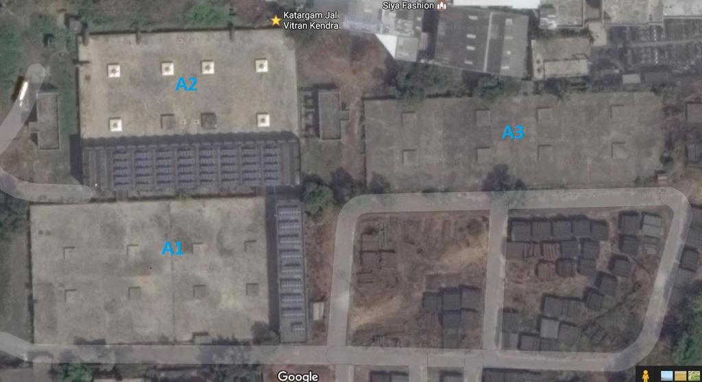
KATARGAM WATER WORKS (940 kwp)
|
|
|
- Georgina Richard
- 5 years ago
- Views:
Transcription
1 1+ BUILDING A1= 992 MODULES PATHWAY (1000) BUILDING A3= 1080 MODULES VENT(4000X4000) PATHWAY (2000) A SHADOW AREA A A SHADOW AREA SHADOW AREA PV MODULE 21 BUILDING BUILDING A2= 960 MODULES BUILDING 1&2 KATARGAM WATER WORKS (940 kwp) Inter row distance 10 Inter module distance Typical module arrangement 01 20/02/17 ARRAY LAYOUT REVISED
2 MODULE IN BHEL SCOPE DETAIL A PU Ø8 MODULE IN BHEL SCOPE 986 PU 1 CH 1 60 CL 1 DETAIL B 21 CH Ø6 CL 2 PU Ø8 CH CL FRONT VIEW SIDE VIEW CL 1 CL 2 PU1 PU1 DETAIL A DETAIL B SLOT FOR MODULE 8 SLOTS Ø8X12 MOUNTING CL 1 CL 2 TOP VIEW
3 A Building A2 = 480 Modules A Building A3 = 640 Modules A PV MODULE Inter row distance Inter module distance Building A1 = 980 Modules KATARGAM WATER DISTRIBUTION STATION (WDS) (650 kwp) Typical module arrangement

4 3942 MODULE IN BHEL SCOPE PU DETAIL A MODULE IN BHEL SCOPE 3226 Ø8 CH 1 60 CL DETAIL B CH Ø6 CL 2 PU Ø HOLE FOR CABLE HOLE FOR CABLE HOLE FOR CABLE CH 2 CL 2 HOLE FOR CABLE PU DETAIL A SIDE VIEW FRONT VIEW MODULE IN BHEL SCOPE DETAIL B CH 1 CL CL 2 CH 2 PU PU CL 1 CL 2 SLOT FOR MODULE MOUNTING 8 SLOTS Ø8X12 ISOMETRIC VIEW TOP VIEW

5

6
7
8 PRODUCT STANDARD ELECTRONICS DIVISION CD REV. 00 A4-10 PAGE 01 OF 01 TECHNICAL SPECIFICATION FOR PV MODULE L24270P (24 V, 300 WATTS) 1. PV MODULE TYPE NO. : L24270P 2. CONFIGURATION :SINGLE GLASS LAMINATED TYPE WITH WITH 72 NOS. OF 156-mm MULTI CRYSTALLINE SILICON SOLAR CELLS (12*6) IN SERIES CONFIGURATION. 3. OVERALL SIZE : 1966 (±3) * 986 (±2) * 35 (±1) mm 4. WEIGHT : 25 Kg. (Typ.) 5. PV MODULE FRAME : ANODISED ALUMINIUM MATERIAL 6. JUNCTION BOX : IP65 GRADE JUNCTION BOX WITH CABLES AND CONNECTORS 7. RFID Tag : As per JNNSM Guidelines 8. TYPICAL ELECTRICAL CHARACTERISTICS : 8.1 OPEN CIRCUIT VOLTAGE (Voc) : 45.0 V 8.2 SHORT CIRCUIT CURRENT (Isc) : 8.7 A 8.3 VOLTAGE AT PEAK POWER POINT (Vmp) : 36 V 8.4 CURRENT AT PEAK POWER POINT (Imp) : 8.34 A 8.5 PEAK POWER OUTPUT (Pmax.) : 300 W (±5%) 8.6 CELL EFFICIENCY : 17.1 % 8.7 MODULE EFFICIENCY : 15.5 % 8.8 FILL FACTOR : 0.70 NOTE : 1. Electrical specifications mentioned above are at Standard Test Conditions of 100 mw/sq. cm solar insolation (AM 1.5) and at 25 deg C temperature. 2. Measurement repeatability of peak power output: ± 3 % REFER MODULE DRAWING NO. : REVISION : (00) APPROVED BY : SR PREPARED ISSUED DATE SM Engg
9 WRENCH RELEASED
10 FRONT VIEW Concrete cover Concrete cover Concrete cover Concrete cover ISOMETRIC VIEW FOR 1 MODULE STRUCTURE ISOMETRIC VIEW FOR 2 MODULE STRUCTURE 2 HOLES Ø8 FOR CLAMP Ø8 HOLE FOR CLAMP Ø6 Hole for Earthing. Ø6 Hole for Earthing FRONT VIEW SIDE VIEW SIDE VIEW Note: Nito bond to be applied as shown in hatched area 1. Provision is given for earthing holes on columns at a distance of 25 mm from the top of pedestal.these holes can be used for holding columns for making the template for pedestal. 2. All dimensions are in mm. 3. Do not scale the drawing only written dimensions to be read. TOP VIEW TOP VIEW FOR BIGGER CHANNEL FOR SMALLER CHANNEL
11 Typical Procedure for In-Situ Casting of Pedestals. 1. Marking of Pedestals as per the Array layout footing. 2. The area marked for the base of the pedestal has to be roughed and then cleaned properly with a brush. 3. Nito bond has to be prepared as per data sheet. 4. Nito bond to be applied on the base of pedestal and then the template for pedestal to be placed on the base and the Channel to be placed as shown in the MMS drawing. 5. The template has to prepared by the vendor in sufficient nos and template to ensure proper position of channel in it. 6. PCC foundation blocks are to be made with 1:2:4 cement concrete. 7. After the template is in position and nito bond applied, 1:2:4 concrete to be poured in it and allowed to dry as per IS Physical inspection of mixing of concrete. 9. The concrete can be made with hand mixing or machine mixing, to be done at site itself. The above procedure has to be applied. Vendor to submit the following documents for Approval to BHEL: 1. Revised procedure for In-situ Casting of pedestals. 2. Template drawing to be used for In situ Casting. Annexures: 1. Nito bond data sheet. 2. Array layout. 3. GA Drawing of Pedestals. Note: Standard procedures along with relevant IS Codes to be followed for the above procedure.
12
13
14 CHAIN LINK FENCE GATE 4000 WBM ROAD LT PANEL LT SIDE 3500 TRF HT SIDE 3000 HT PANEL FRONT SIDE Trenches not indicated. - All dimensions are in mm. - Total Area = 240 sqm. SMC 3.6MW ROOFTOP SPV PLANT TENTATIVE SWITCH YARD LAYOUT
15 At page no 5 & 6 of Specification number PS:439:1121 (f) Insurance & (g) Warranty terms shall be read as: (F) Insurance : 1) BOS vendor shall be required to affect Transit Insurance to the supplies under their scope, under an Insurance policy covering third party liability also valid for entire duration of contract up to date of handing over of facilities (Plant) to SMC. 2) The transit Insurance shall cover transit of BOS Supplied goods from BOS works / BOS sub-vendor works to storage location in Surat and further to various building sites in Surat city. 3) Transit insurance for BHEL supplied goods for the project up to Storage location in Surat and further up to various buildings is in scope of BHEL. 4) A comprehensive Storage cum Erection Cum Commissioning policy shall be taken by BHEL for insurance for entire project supplies and is not included in BOS Vendor scope. 5) Insurance charges, renewal premiums shall be borne by BOS vendor. It is responsibility of BOS vendor to maintain the Insurance policy in force for the entire duration of contract. In case of any loss / claim under the policy, the contractor shall immediately inform the same to BHEL and SMC and lodge the necessary claim and take all measures required for settlement of claim and protect the interest of BHEL, SMC. In case of any delay / lapse on the part of BOS vendor, the loss shall be made up by them by replacing the equipment under claim without waiting for Insurance settlement. (G) Warranty : The successful bidder shall provide a warranty covering the rectification of all defects in the design of equipment, material and workmanship of manufacturing of equipment for a period of 12 (Twelve) months after satisfactory commissioning. The commissioning date for purpose of Start of Warranty will be the date of commissioning of the last item under BOS Vendor scope.