FOUNDATION ANALYSIS AND DESIGN REPORT
|
|
|
- Robert Robinson
- 5 years ago
- Views:
Transcription
1 FOUNDATION ANALYSIS AND DESIGN REPORT TO: FROM: Mark Bishop, PE, Kimley-Hom and Associates, Inc. Jeffery K. Voyen, PE, American Engineering Testing, Inc. DATE: August 28, 2014 SUBJECT: LRT, Freight Rail, and Pedestrian Bridges over Minnehaha Creek Southwest Light Rail Transit Project Minneapolis, Minnesota AETNo PROJECT INFORMATION This report provides foundation analysis and recommendations for the bridges which will carry the light rail transit (LR T) tracks, the re-aligned freight rail tracks, and the pedestrian trail over Minnehaha Creek in St. Louis Park. Separate one-span bridges are planned for each of the three described crossings. The bridges will be long, intended to span Minnehaha Creek and a future trail. The existing bridge foundations and a portion of the abutment front faces are planned to remain in-place. The trail will then be located between the new and old foundations on the west side. Concrete slope paving will be used between the new and old foundations on the east side. With the planned configuration, we understand foundation scour will not be an issue. Out-to-out bridge widths and deck structure types are planned as follows: LRT bridge: , prestressed concrete beams Freight bridge: , steel welded plate girders Trail bridge: , prestressed concrete beams The preliminary bottom of foundation elevation is feet for the west abutment. The foundation at the east abutment could be placed as high as elevation feet, although we are recommending a bottom at elevation feet for geotechnical reasons (to penetrate a clay layer). The plan and profile sheets from the preliminary bridge plans are attached to this report. Based on preliminary plans, the proposed approaches on both sides will be very near or slightly cut into existing grade. The exception is at the freight bridge where the approaches are shown to have a grade raise of about two feet.
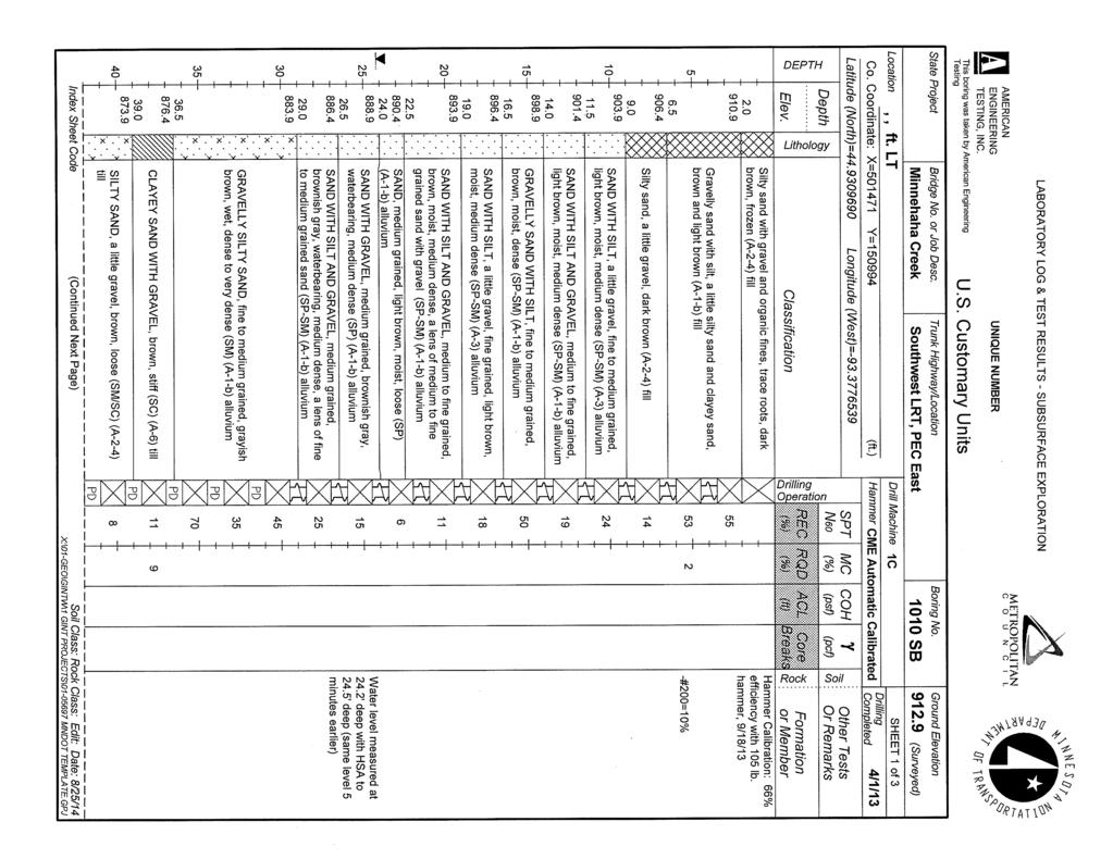
2 Foundation Analysis and Design Report SWLRT, Freight and Trail Bridges Over Minnehaha Creek August 28, 2014 Report No AMERICAN ENGINEERING TESTING, INC. 2.0 SUBSURFACE EXPLORATION SUMMARY 2.1 Scope The exploratory test program performed and included in this report consisted of the following: Trail/Freight West Abutment: CPT 1258 CB, Boring 1009 SB Trail/Freight East Abutment: CPT 1259 CB, Boring 1010 SB LRT West Abutment: Boring 1260 SB LRT East Abutment: Boring 1261 SB Boring 1010 SB also included rock coring once bedrock was reached. The locations of the above listed borings appear on attached Figure Laboratory Scope During laboratory classification logging, water content tests were conducted on cohesive soil samples. In addition, two sieve analysis tests (-#200) were performed. The test results appear on the individual boring logs, opposite the samples upon which they were performed. 2.3 Methods 2.3.J Standard Penetration Test Borings Logs of the above noted borings are attached. The SPT borings were drilled with 3.25 inch diameter hollow stem augers and mud rotary drilling methods. Standard penetration test samples were taken with split-barrel samplers per ASTM: Dl586, with the exception that the hammers were calibrated to near N6o values, consistent with MnDOT requirements. Additional details of the methods used appear on the attached sheet entitled Exploration/Classification Methods. Rock coring was performed in general accordance with ASTM:D2113, using an NQ size wireline system. The soils were classified per the Unified Soil Classification System, although the Soil Group category per the AASHTO Soil Classification System is also noted. The attached boring logs contain information concerning soil layering, soil classification, geologic description, and moisture condition. Relative density or consistency is also noted for the natural soils, which is based on the standard penetration resistance (N-value) Piezocone Penetration Test Soundings CPTu testing was conducted in general accordance with ASTM:D5778; with the user notes, abbreviations, and definitions appearing on the attachment Cone Penetration Test Index Sheet. Field and laboratory testing is done in general conformance with the described procedures. Compliance with any other standards referenced within the specified standard is neither inferred nor implied. Page 2 of 9
3 Foundation Analysis and Design Report SWLRT, Freight and Trail Bridges Over Minnehaha Creek August 28, 2014 Report No AMERICAN ENGINEERING TESTING, INC. 2.4 Geology/Soils Review The generalized geologic profile consists of about 9 feet to 161/z feet of fill overlying waterdeposited (alluvium) granular soils to about elevation 876 feet to 881 feet, which is then mostly underlain by glacially deposited (till) soils. A 21/z-foot layer of organic clay appears above the alluvium (below 161/z feet of fill) at Boring 1260 SB. Bedrock is about 86 feet to 91 feet below the surface Bedrock The bedrock depth at Borings 1009 SB and 1010 SB is 88.8 feet and 91.0 feet, respectively (corresponding to elevation feet and feet). Borings 1260 SB and 1261 SB were obstructed, and pieces of the bedrock were not retrieved. We expect that the obstruction at Boring 1260 SB (75.3 feet deep) was caused by a cobble or boulder. However, the obstruction at 1261 SB may have been the bedrock based on the elevation proximity to the known bedrock elevations. The bedrock is limestone of the Platteville Formation. The rock coring performed at Boring 1010 SB indicates the limestone to be only slightly weathered. RQD values were 92% to 95% Natural Overburden Soils The natural soil profile predominantly consists of alluvium (water-deposited soils) over glacially-deposited till soils. The alluvium is mostly granular, mainly consisting of sand to silty sand having varying gravel content ( at times, mostly gravel). The till mostly consists of clayey sand and silty sand, again having varying gravel content. The upper portion of the till is noticeably looser/softer than the lower zone Upper Fill The borings were drilled on the existing raised embankment. At the boring locations, the fill was 9 feet to 161/z feet thick. The fill is primarily a mixture of sandy soils (sands to silty sands and clayey sands). The N-values indicate relatively high levels of compaction in the existing trail area (based on Borings 1009 SB and 1010 SB) and moderate levels of compaction in the existing freight area (based on Borings 1260 SB and 1261 SB). 2.5 Ground Water Borings 1009 SB and 1010 SB were drilled in March of Ground-water levels measured in the boreholes at that time indicated ground-water level elevations of feet and feet. Borings 1260 SB and 1261 SB were drilled in the spring of The elevations of the levels measured at that time were feet and feet, which corresponded well with the creek level at that time. As these levels were measured in granular soils, they should reasonably represent the hydrostatic ground-water level for that time and location. Ground-water levels should be expected to fluctuate both seasonally and annually, which was evidenced from the 2013 to 2014 levels measured. Page 3 of9
4 Foundation Analysis and Design Report SWLRT, Freight and Trail Bridges Over Minnehaha Creek August 28, 2014 Report No AMERICAN ENGINEERING TESTING, INC. 3.0 FOUNDATION ANALYSIS The following analysis uses Load and Resistance Factor Design (LRFD) methodology. In the future, it may be determined that freight rail bridge foundation analyses needs to follow AREMA standards which use Allowable Stress Design (ASD) methodology. If this is determined to be the case, the report will need to be modified using the preferred methodology during advanced design. 3.1 Foundation Analysis Foundation Type The planned foundations are expected to penetrate through the upper fill and organic clay layers and extend into the natural alluvium. The soils exposed are expected to be the natural sands, with one qualification. CPT 1259 CB (Freight/Trail east abutment) indicates the presence of a marginal clay layer to about elevation 893Vi feet. If bottom of footing elevations on the east side are established at elevation 892 feet, the limiting soils should be penetrated and natural sands exposed. Based on support upon the sands, it is our opinion that a spread footing foundation can be considered for support of these bridges. It should be recognized that the foundations are expected to extend below the ground-water level, and local ground water control will be needed to construct the footings. However, similar ground water control would likely be needed for a pile foundation approach, based on foundation bottom elevations. The alternate to a spread foundation approach would be to support the bridge on H-piles which are driven to the bedrock around elevation 822 feet to 824 feet. This preliminary report, however, presents the spread foundation support only. 3.2 Design Assumptions The profile/elevation view for the LRT bridge is shown on Figure 3.2. The profile views pertaining to the freight and trail bridges are generally similar to this, so are not shown. Page 4 of9
5 Foundation Analysis and Design Report SWLRT, Freight and Trail Bridges Over Minnehaha Creek August 28, 2014 Report No AMERICAN ENGINEERING TESTING, INC. Figure Profile/Elevation View E:,bTI :: r ~,i;.<.'. U, E 'f t fa.:, ). :- L ', EL = Foundation data used in our analysis was determined from the preliminary plans and information provided by Kimley-Horn and Associates, Inc. (KHA), as shown in Table 3.2. Table 3.2 -Foundation Data Substructure Trail West Abutment Trail East Abutment Freight West Abutment Freight East Abutment LRTWest Abutment LRTEast Abutment Bottom of Footing Elevation, ft Footing Width, ft Footing Length, ft Max. Service Loads (nominal), ksf Maximum Strength Loads (factored), ksf * * * *recommended to penetrate clay layer (and keep side-by-side footings at same elevation) 3.3 Foundation Analysis Discussion The natural granular soils are judged capable of supporting a spread footing foundation system for the new bridges. If clays happen to be present in the excavation bottom, the analysis assumed they will be subcut and replaced with sand/gravel as discussed later. Page 5 of9
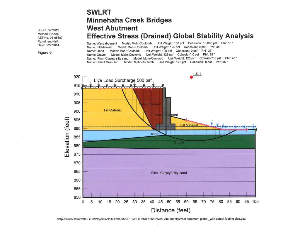
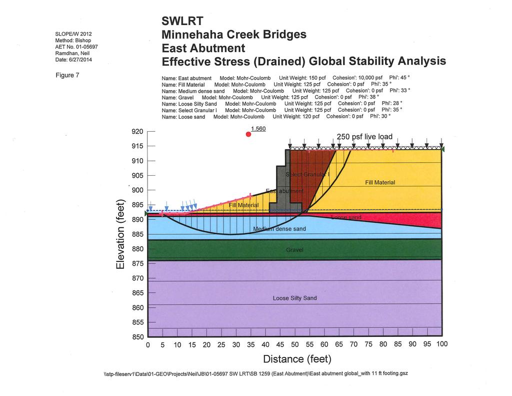
6 Foundation Analysis and Design Report SWLRT, Freight and Trail Bridges Over Minnehaha Creek August 28, 2014 Report No AMERICAN ENGINEERING TESTING, INC Nominal Bearing Resistance - Strength Limit State The nominal (ultimate) bearing resistance of the spread footing foundations was evaluated using the bearing resistance formula presented in Section 10 of the AASHTO LRFD Bridge Design Specifications, The internal friction angle of the granular bearing soils was correlated to SPT N-values obtained in the borings. The results of our foundation analyses for varying footing widths pertaining to the Strength Limit State appear on Figures 2 to 5, attached to this report Nominal Bearing Resistance - Service Limit State Footing settlement was estimated by computing Young's modulus values using the shear wave velocities determined from the CPTu soundings and an assumed Poisson's ratio of 0.2, with reduction factors applied to the dynamic (i.e. small-strain moduli) to account for the variation of modulus with strain level under static loading. Changes in total vertical stress due to foundation loading from the footings were evaluated by Boussinesq equations. The results of our foundation analyses for varying footing widths pertaining to the Service Limit State appear on Figures 2 to 5, attached to this report Sliding Resistance of Abutment Footings We assume that the concrete for the footing will be poured directly onto the sandy foundation soils. It is also assumed that the passive resistance in front of the footings will be ignored Global Stability Analysis The global stability of the abutments was checked using Bishop's Modified method of slices using the computer program SLOPE/W It is assumed that a minimum factor of safety of 1.5 would be acceptable. The footing was modeled as a very strong material, thus forcing the critical failure surface behind the heel of the footing. Based on information from KHA, we evaluated a live load surcharge of either 250 psf (for the pedestrian and LRT bridges) or 500 psf (for the freight rail bridge). For the west abutments, we analyzed geometry including an 11-foot wide footing, with the 500 psf live load, and a representative soil profile. We found a factor of safety of 1.51, which meets the minimum required value. For the east abutments, we first analyzed an 11-foot wide footing, with the 250 psf live load associated with the pedestrian and LRT bridges, for which we found a factor of safety of We also analyzed a 13-foot wide footing with the 500 psf live load surcharge associated with the freight bridge, and we found a factor of safety of The results of our global stability analyses appear on Figures 6 to 8, attached to this report. Page 6 of9
7 Foundation Analysis and Design Report SWLRT, Freight and Trail Bridges Over Minnehaha Creek August 28, 2014 Report No AMERICAN ENGINEERING TESTING, INC. 4.0 FOUNDATION RECOMMENDATIONS 4.1 Foundation Type and Depth Based on our interpretation of the subsurface conditions, the bridges can be supported on conventional spread footing foundations. Footings should be supported at least 4.5 feet below final grade for frost protection. The planned footing depths do exceed this minimum cover depth. 4.2 Footing Design Nominal Bearing Resistance - Strength Limit State The maximum factored bearing pressure should be maintained below the factored bearing resistance (nominal bearing resistance provided at the effective footing width times a Resistance Factor of 0.45). Based on the preliminary information, it appears this requirement will be satisfied, but should be re-evaluated once loads based on the effective footing width are established. If the maximum factored bearing pressure exceeds the factored bearing resistance provided at the effective footing width, the footing should be widened until the criterion is met Nominal Bearing Resistance - Service Limit State To maintain settlements within the 1-inch criteria, the nominal bearing resistance should be maintained below the limits established in Figures 2 to 5. The final nominal bearing resistance will need to be met using the effective footing width. The preliminary data suggests this requirement should be met, but should be re-evaluated once loads based on the effective footing width are established Sliding Resistance The shear resistance of the sandy soils along the base of the footing should be able to resist the computed lateral loads. This will allow the passive resistance from the soils in front of the footing to be ignored. This evaluation can be based on the following recommended parameters: a friction angle of 32 degrees for cast-in-place concrete on the sandy foundation soils, a Nominal Sliding Resistance of 0.60 times the applied vertical force, and a Resistance Factor of Global Stability of Abutments The calculated factors of safety for the critical surfaces developed for the West and East Abutment analyses are about 1.5 and 1.55, respectively. Both meet or exceed 1.5, and are acceptable. 4.3 Dewatering and Excavation/Filling Needs Dewatering The excavation to bottom of footing elevation is expected to extend up to 4 feet below the most recent water level measurements, although this is expected to fluctuate with time. Accordingly, dewatering will be needed to properly construct the foundations. This will likely need to be in the form of a local cofferdam, wherein the direct inflow of water from the bottom and sides can Page 7 of9
8 Foundation Analysis and Design Report SWLRT, Freight and Trail Bridges Over Minnehaha Creek August 28, 2014 Report No AMERICAN ENGINEERING TESTING, INC. be controlled. The till soils below about elevation 875 feet to 880 feet offers a less permeable deposit than the upper sands for at least a partial "seal" using this approach Potential Over-Excavation The bearing soils exposed during construction should be observed, probed with hand auger borings, and evaluated for suitability by a geotechnical engineer/technician. If clayey, organic, or excessively soft/loose soils are encountered, they should be subcut further and replaced with compacted granular fill. The excavation should continue to extend out horizontally from the edge of foundations a distance at least equal to the depth of fill required to establish grade, forming a 1 : 1 oversizing Engineered Fill Soil Type and Compaction below Foundations Based on the borings/cpts, it is not expected that over-excavation is needed. However, if it is needed, engineered fill would need to be placed. Engineered fill placed to establish foundation grade should at least meet the requirements of MnDOT Specification B2, Select Granular Borrow. This granular fill should be placed and compacted in accordance with MnDOT Specification Compaction should meet the Specified Density Method, with the modification that the entire thickness of the new fill below the footing be compacted to a minimum of 100% of the Standard Proctor density. If excess water is present, open-graded gravel (such as Coarse Filter Aggregate per MnDOT H) could be used. Open-graded gravels must be separated from surrounding soils with a geotextile separation fabric (Type V geotextile per MnDOT 3733) to prevent internal erosion of fines into the open void space. 4.4 Abutment Backfilling The imbalanced abutment walls must be designed to resist the lateral pressures exerted. The backfill material should consist of Select Granular Borrow (MnDOT B2), which is modified to containing less than 10% by weight passing the #200 sieve. The "Select Granular Borrow 10% Modified" geometry should be maintained per the requirements shown on attached MnDOT Diagram F-1. However, all excavation backsloping must also meet OSHA requirements and the need for frost zone tapering below the roadway. For proper track/trail approach performance, frost tapering of the Select Granular Borrow below the tracks/trail of 1 V:20H should be maintained within the frost zone (assume a frost zone of 4.5 feet). The backfill should be compacted per the Specified Density Method (MnDOT Fl). The wall design can be based on lateral pressures presented in MnDOT design charts. Page 8 of9
9 Foundation Analysis and Design Report SWLRT, Freight and Trail Bridges Over Minnehaha Creek August 28, 2014 ReportNo AMERICAN ENGINEERING TESTING, INC. I hereby certify that this report was prepared by me or under my direct supervision and that I am a duly Licensed Professional Engineer under Minnesota St ute Section 3; 6J2 to Name: /.. /{/d.,e,""' effe y K. Voyen Date: t',/zjj:/t'( License#: Report Reviewed By:,_ /)~ -...,. - ~ J~ '-"~~~J~~ ~ G.B;nder, PE Attachments: Preliminary Bridge Plan-Profile Sheets Figure 1 - Boring and CPT Locations Subsurface Boring Logs Cone Penetration Test Logs Figures 2 to 5 - LRFD Bearing Graphs Figures 6 to 8 - Global Stability Analysis Exploration/Classification Methods Boring Log Notes Unified Soil Classification System AASHTO Soil Classification System Cone Penetration Test Index Sheet MnDOT Diagram F-1 Page 9 of9

10

11

12
13
14
15
16
17
18
19
20
21
22
23
24

25

26
27
28
29
30
31
32
33
34 EXPLORATION/CLASSIFICATION METHODS SAMPLING METHODS Split-Spoon Samples (SS) - Calibrated to N 60 Values Standard penetration (split-spoon) samples were collected in general accordance with ASTM: D1586 with one primary modification. The ASTM test method consists of driving a 2" O.D. split-barrel sampler into the in-situ soil with a 140-pound hammer dropped from a height of 30". The sampler is driven a total of 18" into the soil. After an initial set of 6 11, the number of hammer blows to drive the sampler the final 12" is known as the standard penetration resistance or N-value. Our method uses a modified hammer weight, which is determined by measuring the system energy using a Pile Driving Analyzer (PDA) and an instrumented rod. In the past, standard penetration N-value tests were performed using a rope and cathead for the lift and drop system. The energy transferred to the split-spoon sampler was typically limited to about 60% of its potential energy due to the friction inherent in this system. This converted energy then provides what is known as an N 60 blow count. Most of today's drill rigs incorporate an automatic hammer lift and drop system, which has higher energy efficiency and subsequently results in lower N-values than the traditional N 60 values. By using the PDA energy measurement equipment, we are able to determine actual energy generated by the drop hammer. With the various hammer systems available, we have found highly variable energies ranging from 55% to over 100%. Therefore, the intent of AET's hammer calibrations is to vary the hammer weight such that hammer energies lie within about 60% to 65% of the theoretical energy ofa 140-pound weight falling 30". The current ASTM procedure acknowledges the wide variation in N-values, stating that N-values of 100% or more have been observed. Although we have not yet detennined the statistical measurement uncertainty of our calibrated method to date, we can state that the accuracy deviations of the N-values using this method are significantly better than the standard ASTM Method. Sampling Limitations Unless actually observed in a sample, contacts between soil layers are estimated based on the spacing of samples and the action of drilling tools. Cobbles, boulders, and other large objects generally cannot be recovered from test borings, and they may be present in the ground even if they are not noted on the boring logs. CLASSIFICATION METHODS Soil classifications shown on the boring logs are based on the Unified Soil Classification (USC) system. The USC system is described in ASTM: D2487 and D2488. Where laboratory classification tests (sieve analysis or Atterberg Limits) have been perfonned, accurate classifications per ASTM: D2487 are possible. Otherwise, soil classifications shown on the boring logs are visual-manual judgments. Charts are attached which provide information on the USC system, the descriptive terminology, and the symbols used on the boring logs. Visual-manual judgment of the AASHTO Soil Group is also noted as a part of the soil description. A chart presenting details of the AASHTO Soil Classification System is also attached. The boring logs include descriptions of apparent geology. The geologic depositional origin of each soil layer is interpreted primarily by observation of the soil samples, which can be limited. Observations of the surrounding topography, vegetation, and development can sometimes aid this judgment. WATER LEVEL MEASUREMENTS The ground-water level measurements/comments are shown on the boring logs in the remarks section. The true location of the water table at the boring locations may be different than the water levels measured in the boreholes. This is possible because there are several factors that can affect the water level measurements in the borehole. Some of these factors include: permeability of each soil layer in profile, presence of perched water, amount of time between water level readings, presence of drilling fluid, weather conditions, and use of borehole casing. SAMPLE STORAGE Unless notified to do otherwise, we routinely retain representative samples of the soils recovered from the borings for a period of 30 days. 01REP051C (12/08) AMERICAN ENGINEERING TESTING, INC.
35 BORING LOG NOTES DRILLING AND SAMPLING SYMBOLS Symbol Definition AR: Sample of material obtained from cuttings blown out the top of the borehole during air rotary procedure. B,H,N: Size of flush-joint casing CAS: Pipe casing, number indicates nominal diameter in inches COT: Clean-out tube DC: Drive casing; number indicates diameter in inches DM: Drilling mud or bentonite slurry DR: Driller (initials) DS: Disturbed sample from auger flights DP: Direct push drilling; a inch OD outer casing with an inner 11h inch ID plastic tube is driven continuously into the ground. FA: Flight auger; number indicates outside diameter in inches HA: Hand auger; number indicates outside diameter RSA: Hollow stem auger; number indicates inside diameter in inches LG: Field logger (initials) MC: Column used to describe moisture condition of samples and for the ground water level symbols N (BPF): Standard penetration resistance (N-value) in blows per foot (see notes) NQ: NQ wireline core barrel PD: Plug Drilling (same as RDF) PQ: PQ wireline core barrel RDA: Rotary drilling with compressed air and roller or drag bit. RDF: Rotary drilling with drilling fluid and roller or drag bit REC: In split-spoon ( see notes), direct push and thin-walled tube sampling, the recovered length (in inches) of sample. In rock coring, the length of core recovered (expressed as percent of the total core run). Zero indicates no sample recovered. SS: Standard split-spoon sampler (steel; 1.5'' is inside diameter; 2" outside diameter); unless indicated otherwise SU Spin-up sample from hollow stem auger TW: Thin-walled tube; number indicates inside diameter in inches WASH: Sample of material obtained by screening returning rotary drilling fluid or by which has collected inside the borehole after "falling" through drilling fluid WH: Sampler advanced by static weight of drill rod and hammer WR: Sampler advanced by static weight of drul rod 94mm: 94 millimeter wireline core barrel T: Water level directly measured in boring V: Estimated water level based solely on sample appearance TEST SYMBOLS Symbol Definition COH: Cohesion, psf (0.5 x qu) CONS: One-dimensional consolidation test y: Wet density, pcf DST: Direct shear test E: Pressuremeter Modulus, tsf HYD: Hydrometer analysis LL: Liquid Limit, % LP: Pressuremeter Limit Pressure, tsf MC: Moisture Content, % OC: Organic Content, % PERM: Coefficient of permeability (K) test; F - Field; L - Laboratory PL: Plastic Limit, % qp: Pocket Penetrometer strength, tsf (approximate) qc: Static cone bearing pressure, tsf qu: Unconfined compressive strength, psf R: Electrical Resistivity, ohm-ems RQD: Rock Quality Designation of Rock Core, in percent (aggregate length of core pieces 4" or more in length as a percent of total core run) SA: Sieve analysis TRX: Triaxial compression test VSR: Vane shear strength, remolded (field), psf VSU: Vane shear strength, undisturbed (field), psf %-200: Percent of material finer than #200 sieve STANDARD PENETRATION TEST NOTES (Calibrated Hammer Weight) The standard penetration test consists of driving a split-spoon sampler with a drop hammer ( calibrated weight varies to provide N 60 values) and counting the number of blows applied in each of three 6 11 increments of penetration. If the sampler is driven less than 18" (usually in highly resistant material), permitted in ASTM: D1586, the blows for each complete 6" increment and for each partial increment is on the boring log. For partial increments, the number of blows is shown to the nearest 0.1' below the slash. The length of sample recovered, as shown on the "REC" column, may be greater than the distance indicated in the N column. The disparity is because the N-value is recorded below the initial 6" set (unless partial penetration defined in ASTM: Dl586 is encountered) whereas the length of sample recovered is for the entire sampler drive (which may even extend more than 18"). 01REP052C (7/11) AMERICAN ENGINEERING TESTING, INC.

36
37

38
39