Network Rail Track Bed Micro Piling
|
|
|
- Chad Barton
- 5 years ago
- Views:
Transcription


1 Network Rail Track Bed Micro Piling Peter Musgrave Mohamed Wehbi Track Engineering Conference 17th July
2 Micro-piling What good & poor track bed looks like Installation methodology & theory Potential applications and advantages Trials and design modelling to date 2

3 What Good Track Bed Looks Like No treatment required. Good track quality, low deterioration and high residual life HSTRC responses represent structures 3

4 What Good Looks Like 4
.")


5 Poor performance further investigation Poor performing sections are located on poor sub-grade (natural ground or fill). Further trackbed investigation has been recommended to determine the cause of high deterioration through these sections. This section has had a the same renewal treatment throughout, with an additional 600mm construction depth with no features identified on HD video. The high peak in the GPR corresponds to the worst of track geometry which suggests potential subgrade erosion or this may be an issue of peat settlement. 5

6 Micro Piling Methodology Has been widely used in the construction industry for many years. It is typically used to underpin existing structures or to create foundations for highways, bridges or transmission towers. Over the last 3 years the Network Rail track bed investigation team has been working with Aspin Foundations, an established pilling supplier, to adapt the technology for use in track applications. 6
7 Load distribution before piling P P Ballast Formation Weak soil Strong soil 7
8 Load distribution after piling P P Ballast Formation Weak soil Strong soil %P (bearing resistance) 8
9 Pile Construction Options Steel (screw piles) Granular Piles Concrete Piles Sand Columns 9

10 Pile Construction Pile formed in disposable cardboard tube using ballast & resin to form free draining pile 10

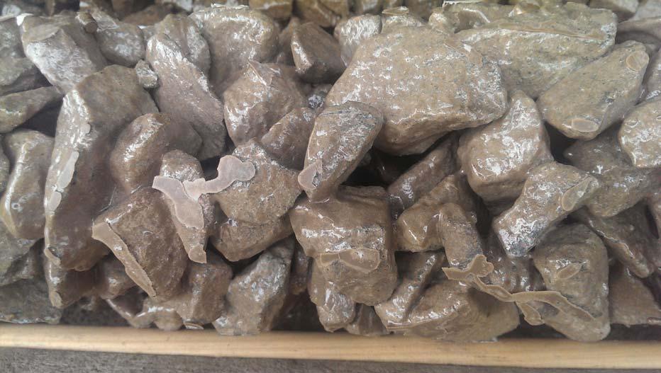
11 Pile Construction Resin Bonded Ballast pile 11
12 Potential applications and advantages Micro-piling is being developed to: Treat critical velocity (TSR) sites Provide an alternative to full formation renewal in some cases Be used as part of the solution to refurbish S&C Advantages Can be installed in short possessions and in stages for a particular site The stone column variant is designed to provide a natural soak away and help manage water in poor drainage locations The steel variant is Network Rail product approved Pile cap is installed between mm below base of sleeper / bearer so no conflict with future renewals work (inc. ballast cleaning). Does not require track component removal or signal disconnections during installation 12
13 Design verification trial sites and modelling Live trials We have installed steel micro-piles at 4 locations on the West Coast Main line to address critical velocity issues and we will continue to monitor The track has been stabilised to the extent to which existing Temporary Speed Restrictions (TSR) have been removed and line speed of 125mph restored Finite Element Analysis modelling The FEA model has been undertaken to enhance the fundamental sub-system design of the steel piles and stone columns. The Birmingham University Track Bed Model to help design the best pile / stone column configuration on a site by site basis 13
14 Progress to Date R&D Design development (inc. Failure Mode and Effects Analysis) Ongoing design verification modelling, rig testing, in-track testing and measurement Performance Specification Developed & Issued to Professional Head of Track Planning for Production Working with RAMs to build CP5 work-bank & develop a programme Developing a procurement strategy for initial trial sites Technical refinement of the delivery methodology is ongoing Design Some trial sites identified Design Tools developed 14
15 Design Simulation Model Scope Different piles material (Steel, stone/concrete/sand) Different ballast thicknesses (200mm, 300mm, 400mm) Different piles lengths (1.5m, 3.5m, 5.5m) Different train speeds (100mph, 150mph, 200mph)» Different soil conditions (very soft, soft, medium, medium to stiff 15


16 Purpose of Design Model 16
17 Design Model Performance (outputs) Track quality Maximum rail deflection Dynamic stiffness FWD stiffness MGT (life expected) 17


18 Progress To date 18
19 Pile configurations tested in the Birmingham University model 19

20 Stresses with no piles Note stress concentration in formation and soil layer 20

21 Stress distribution in the simulation after piling Pile Ballast and formation Weak Soil Strong soil 21


22 300mm ballast, 100 mph (short-term performance) 22


23 300mm ballast, 100 mph (Short-term performance) 23


24 300mm ballast, 100 mph (Long-term performance) 24

25 Computer Software 25

26 Computer Software 26

27 Computer Software 27
28 Any Questions? 28