FOUNDATIONS FOR OFFSHORE STRUCTURES
|
|
|
- Christopher Russell
- 5 years ago
- Views:
Transcription


1 Part-I Foundation concepts FOUNDATIONS FOR OFFSHORE STRUCTURES DELHI CHAPTER Pradeep Hora Virtually every structure is supported by soil or rock. Those that aren't either fly, float, or fall over. - Richard L. Handy,
2 The Offshore Industry Historical perspective First well drilled out of sight of land in 1947 in 6.0m w.d. Today, we are drilling in 3000m First offshore platform installed in 1947 in 6.0m Today, platforms are installed in depths exceeding 2500m World s tallest structure was installed offshore in 1979 in 114m Today, a fixed platform stands in excess of 550m First subsea tree installed in early 1960 s in less than 90m Today, subsea trees are installed in over 2750m 3 The Offshore Industry - India Historical perspective Offshore Oil & Gas Exploration Sagar Samrat - Jack up Rig Commercial find Mumbai High Western Offshore India First offshore platform NA Platform 1977 Eastern Offshore India Subsea Structures in 1200m water depth KG Block 4 2

3 Offshore Geotechnical Activities at IITD Historical perspective Thermal conductivity of marine soils Engineering properties of Carbonate soils Engineering properties of Corals and carbonate clays FEM code Wave Induced Soil Movements Marine Anchors 5 6 3


")
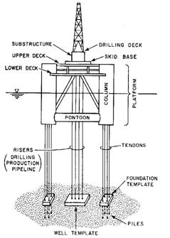
4 Offshore Structures Bottom supported structures Spud can 14~22m dia. Jacket Jack-up rig Gravity base Compliant Tower 7 Offshore Structures Floating structures Tension Leg Platform (TLP) Semisubmersible SPAR FPSO 8 4
5 What makes offshore very different? Site investigations: Soil Conditions: Applied Loads: Design modifications: Installation: Extremely expansive, hire costs several millions of dollars (Suitability of vessel to operate in the given environment, opportunity costs) Unusual, various types (particularly Carbonate/ Calcareous, Corals Large, high component of environment loads, large lateral loads as compared to weight of structure Loads - Static, Cyclic, Dynamic, Transient During construction generally not possible, Remedial measures very expansive, incur severe cost penalties Logistics Marine spread, weather window, magnitude 9 Expect the Unexpected...as we know, there are KNOWN KNOWNS: there are things we know. We also know there are KNOWN UNKNOWNS: that is to say we know there are some things we do not know. But there are also UNKNOWN UNKNOWNS: the one s we don t know we don t know. Former U.S. secretary of Defence Donald Rumsfeld 10 5
 Pile driving problems")

, shifting sands, hard clays, soft soils India Eastern")

 TLPs FPSO FPS SPAR General multi-footing Structures Jacket Structures Tension")
6 Soil Types Offshore Environment Gulf of Mexico - Soft Clays, delta area Wave induced soil movement & slope failures, Pile-soil set up North Sea Stiff to Hard Silty, Bouldry Clays (OC Clays) Pile driving problems Middle East Cemented Sands, Calcarenite, Hard Clays, Pile refusal, Pile relaxation, pile acceptance Australia Carbonate soils Low capacity, remedial measures Brazil Dense Sands Western Africa Stiff to Hard Clays (NC To OC Clays) South China Sea Soft Clays/ Dense Sands India Western Offshore Calcareous/ Carbonate, Corals - Soils (High Spatial Variation), shifting sands, hard clays, soft soils India Eastern Offshore Very Soft to soft Clays (U/C to NC Clay) Deltaic regions - Collapsible, Wave induced soil movements & slope failures 11 Offshore Structure Foundation Types Deep Foundations or Pile foundation Anchoring system Shallow foundation Gravity based structure Jacket Bucket Foundations Hybrid Structures Tension Leg Platform (TLP) TLPs FPSO FPS SPAR General multi-footing Structures Jacket Structures Tension Leg Platform (TLP) Compliant Towers Spud can 12 6


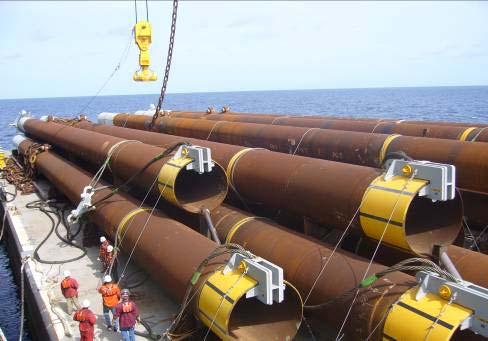
7 Jacket Installation 13 Pile Foundations for Jacket Structures Usually open ended steel pipes Variable wall thickness Variable strength Long Deep penetrations Single pile or pile group per leg Typical properties of offshore piles Diameter 610 to 3000 mm Variable wall thickness 16 to 95 mm Variable strength 245 to 350 MPa Long deep penetrations 30.0m to 150.0m Installation in number of sections or single length Typical loads Axial 10 to 100 MN/ pile Lateral ~ 1 to 5 MN/ pile 14 7


8 Pile Installation Impact Driven Piles Pile Driving Impact Hammers - Steam Hammers - Hydraulic Hammers - Diesel Hammers Pile Driving Vibratory Hammers Drilled & Grouted Piles 15 Pile Installation through Jacket Legs Main Piles Through jacket legs Driven by hammer Secured by welding shims to jacket legs & if required secured also by grouting the annulus 16 8


9 Pile Installation through Skirt Sleeves Skirt Piles Through Sleeves. Driven with under water hammer or chaser pile Secured by grouting the annulus 17 Pile Installation Drilled & Grouted 18 9


10 Drilled & Grouted Piles Likely use of drilled & grouted piles Very Stiff to Hard clays Cemented soils Calcareous soils Possibility of refusal at shallow depths Diameter Length 24 in to 120 in 100 ft to 500 ft Oil Well Conductors - 18 in to 26 in - more than 1500ft Installation Problems 19 Flanged Air Lift Drill Pipe Stabilizer Drill Collar Stabilizer Drill Bit Under Reamer 20 10

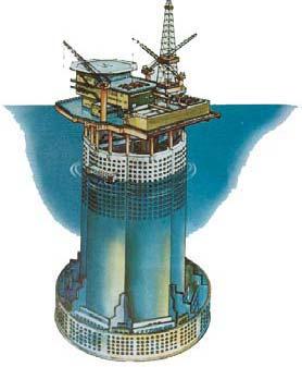
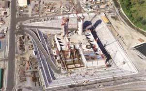
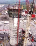
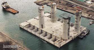
11 Gravity Based Structures (GBS) 21 Malampaya GBS The Arup Journal 1/


 M=f(Hh)")
12 23 Foundation loads h V H Self weight of structure and foundation system Wind, wave and current forces acting on substructure (H,M) M=f(Hh) VHM foundation loads 24 12


13 35% extra V 1600% extra H 500% extra M Foundation plan 9173 m 2 A 3692 m 2 150% bigger foundation area 25 Hybrid Structure The Maureen Alpha platform is a steel gravity base structure with a weight of 112,000 ton, height of 241 meters and steel skirts for penetration into the seabed. On June 27, 2001 the gravity based Maureen Alpha Platform, located in the Maureen Field at the U.K. Continental Shelf Block 16/29a, was successfully removed and towed to the western coast of Norway for demobilization and possible re-use
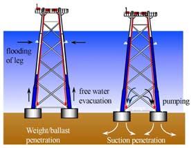
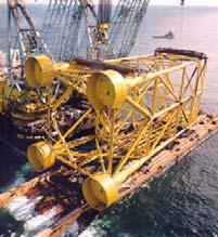
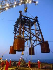
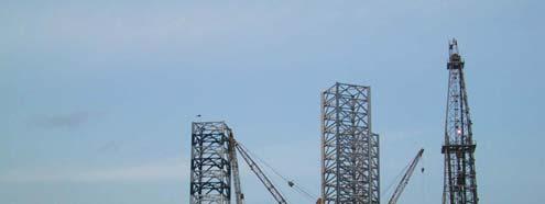
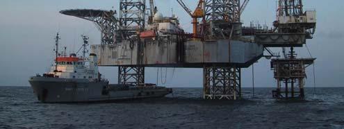
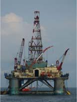
14 Bucket foundations DD D 27 Jack-up Rig 28 14

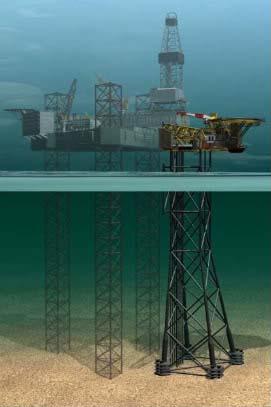
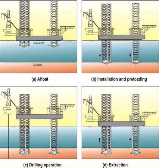
15 29 Jack-Up Rig Installation 30 15

 Gas pockets / Shallow gas Drilling control flushing in conductors poor cement : gas Scour Storm vertical settlement and sliding Unit removal")
16 Jack-Up Hazards Seabed obstructions metallic or otherwise Leg penetration, raising the hull + preloading Buried items anchors, pipelines Seabed irregularities footprints pockmarks, reefs, pinnacles Seabed inclination Buried inclined hard layer Adequate leg length Rapid leg penetrations Punch-through Geo-hazards (mudslides, mud volcanoes, seismic activity, faults etc.) Gas pockets / Shallow gas Drilling control flushing in conductors poor cement : gas Scour Storm vertical settlement and sliding Unit removal Leg extraction difficulties 31 Punch through Failure 32 16

17 Scour around jack-up footings can increase punch-through risk 33 Historical Back Ground 34 17

. At present the deepest is Petronius in 535 m of water.")
18 Compliant Towers Piled, Articulated, Guyed A compliant tower is similar to a traditional jacket platform and extends from surface to the sea bottom. Unlike jacket platforms, a compliant tower is designed to flex with the forces of waves, wind and currents. The first tower emerged in the early 1980s Compliant towers are designed to sustain significant lateral deflections and forces, and are typically used in water depths ranging from 1,500 and 3,000 feet (450 and 900 m). At present the deepest is Petronius in 535 m of water. 35 Compliant Towers Piled, Guyed 36 18


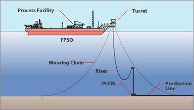
19 37 Floating Structures - Anchoring Systems 38 19

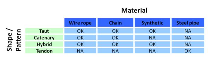
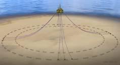
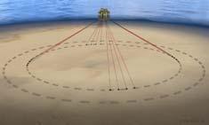
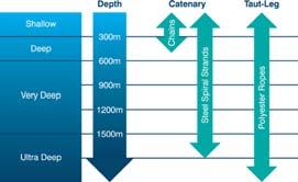
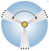
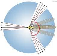
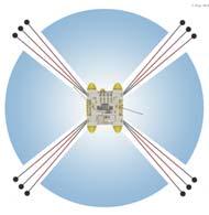
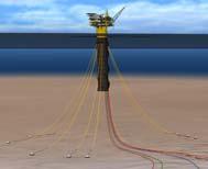
20 Possible Offshore Mooring Configurations 39 Possible Offshore Mooring Configurations 40 20


21 Drag Anchors 41 High Holding Power Drag Anchors 42 21


 44")
22 Anchor Handling Tug (AHT) in Action 43 Drag Embedment Plate Anchor Types Direct Embedment (SEPLA) 44 22

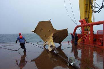
23 Drag Embedment


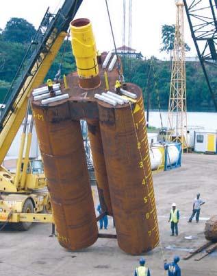
24 Drag Embedded Vertically Loaded Anchors 47 Suction Anchors Stiffened cylindrical shell D: m L: 5-20m Open base and enclosed top


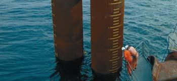
25 49 Group Suction Anchors 50 25
 52")
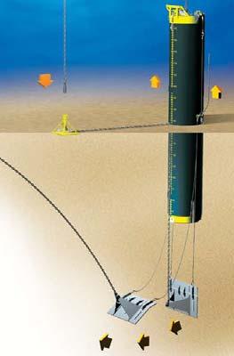
26 Suction Anchors 51 Suction Embedded Anchors (SEA) 52 26


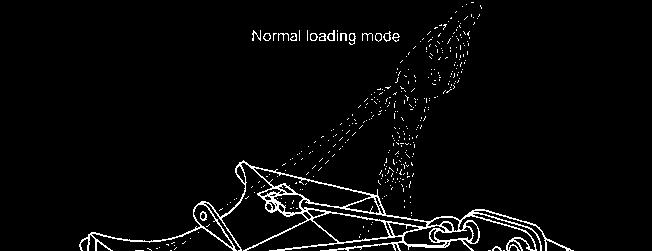
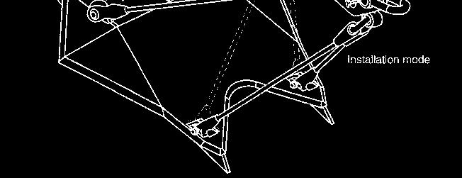
27 SEA 53 SEA opening trajectory 1. Embed SEA using suction follower 2. Release rigging 3. Open SEA by reversed suction process 4 SEA ready for use 54 27


")


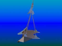
28 Holding Capacity of SEA SEA Capacity High capacity vs. own weight ratio (100:1) Independent on load angle 55 Follower + SEPLA Anchor (Suction Embedded Plate Anchor) 56 28
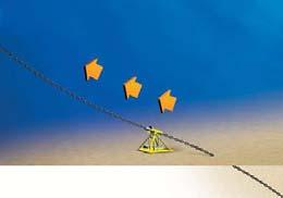
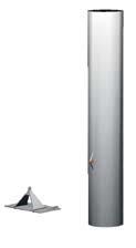
29 SEPLA Installation 57 Suction Embedded Plate Anchors (SEPLA) 58 29
 (Torpedo Anchor)")
 59 Dynamically")

30 Deep Penetrating Anchor (DPA) (Torpedo Anchor) (Dynamically Penetrating Anchor) 59 Dynamically Penetrating Anchor Installation 13~15 metre-long 80~110-ton anchor 60 30
31 Dynamically Penetrating Anchor 61 Driven Anchor Piles 62 31


32 Seabed Pile Driving Frame & Underwater Hammer 63 Foundations for offshore wind farm structures Shallow Foundations Mono Piles Bucket Foundations GBS Jacket Structures Piles Shallow Floating - Anchored 64 32
33 Questions 65 These presentations are for the purpose of generating awareness in the field of Marine Geotechnology and Foundations for Offshore structures with no commercial intent. Reference: The list below is not exhaustive. API (2000) & Errata & Supplement 1, 2 & 3 (2002, 2005 & 2007) Recommended Practice for Planning, Designing and Constructing Fixed Offshore Platforms Working Stress Design, API RP 2A, American Petroleum Institute, Washington, USA. API (2005) Recommended Practice for Design and Analysis of Station Keeping Systems for Floating Structures, API RP 2SK, American Petroleum Institute, Washington, USA. API (2011) Geotechnical and Foundation Design Considerations, API GEO, American Petroleum Institute, Washington, USA. Herbich, J.B (1991) Handbook of Coastal and Ocean Engineering, Gulf Publishing Co. McCarron, W.O. (2011) Deepwater Foundations and Pipeline Geomechanics, Joss Publishing. OTC (1969 to 2013) Proceedings Annual Offshore Technology Conference, OTC Volumes, Houston Texas, USA Le Tirant, P. (1979) Seabed Reconnaissance and Offshore Soil Mechanics for the Installation of Petroleum Structures, Ed. Technip, Paris Poulos, H.G. (1988) Marine Geotechnics. Unwin Hyman, London. Rendolph, M. & Gourvenec, S. Offshore Geotechnical Engineering, Spon Press, New York, USA

34 Various Internet Sites: Thank you for your attention Foundations Part-I Foundation for Offshore Concepts Structures May January 20131,