Access Road Construction of the Larsi Building Using Reinforced Earth Walls
|
|
|
- Bonnie Wright
- 5 years ago
- Views:
Transcription


1 Missouri University of Science and Technology Scholars' Mine International Conference on Case Histories in Geotechnical Engineering (2013) - Seventh International Conference on Case Histories in Geotechnical Engineering Apr 29th - May 4th Access Road Construction of the Larsi Building Using Reinforced Earth Walls Amir Eslami Amirabadi University of Tehran, Iran Atefeh Zamani Sharif University of Technology, Iran Cambyse Behnia University of Tehran, Iran Follow this and additional works at: Part of the Geotechnical Engineering Commons Recommended Citation Amirabadi, Amir Eslami; Zamani, Atefeh; and Behnia, Cambyse, "Access Road Construction of the Larsi Building Using Reinforced Earth Walls" (2013). International Conference on Case Histories in Geotechnical Engineering This Article - Conference proceedings is brought to you for free and open access by Scholars' Mine. It has been accepted for inclusion in International Conference on Case Histories in Geotechnical Engineering by an authorized administrator of Scholars' Mine. This work is protected by U. S. Copyright Law. Unauthorized use including reproduction for redistribution requires the permission of the copyright holder. For more information, please contact scholarsmine@mst.edu.

2 ACCESS ROAD CONSTRUCTION OF THE LARSI BUILDING USING REINFORCED EARTH WALLS Amir Eslami Amirabadi Atefeh Zamani Cambyse Behnia University of Tehran Sharif University of Technology University of Tehran Jamalzade Ave., Tehran, 14198, Iran Jamalzade Ave., Tehran, 14198, Iran Jamalzade Ave., Tehran, 14198, Iran ABSTRACT Mountainous road construction is one of the most difficult and challenging problems in geotechnical engineering. Geometrical complexities and geotechnical conditions make them different from many other urban projects. Retaining wall system is a principal part of these projects. Reinforced Earth Wall system can be considered as an appropriate option for mountainous road construction. In this case history, access road construction of the LARSI building (Shemshak-Iran) is discussed. Shemshak is a tourist town which is located in southern hillsides of the Alborz Mountains. Therefore, the access road is an essential component particularly in cold seasons. Nine terraced levels of the reinforced earth wall were designed according to the geometrical considerations. The walls reinforcements were evaluated by TALREN 4 V There had been some limitations, etc. which resulted in many challenges during the construction. This project was constructed in six months. INTRODUCTION Reinforced earth was first invented by Henry Vidal, a French engineer, in the early 60s. The principle of reinforced earth is in the use of grainy soil and strip, which have a high amount of tensile strength. Simultaneously the structure ends up with a skin which provides a layer in order to prevent soil grains from falling down and in addition improves the aesthetic value of the structure. There are many advantages in reinforced earth wall like as: being economic, coordinating with soil structures and having high flexibility so that it can bear large settlements and even other movements without any serious danger. Road construction in mountainous areas is one of the most difficult problems in civil engineering. Geometrical complexity and slope stabilization are of special importance. The climate, pavement conditions, and construction difficulties are considered as main factors in the design process. All factors must be seen in such a way that the whole project gets economically efficient. This study focuses on an access road located in the southern hillsides of the Alborz Mountain (Shemshak). Figure 1 shows the geographical situation of the project. The project location is surrounded by a building in the north, villas in the east, the Larsy building in the south and a 60 degree slope in the west. Height difference between the highest and lowest point is about 36 meters (Fig. 2). Fig. 1. Geographical location of the project The road connects the main road to the existing building and the hotel which is going to be constructed in the future (Fig. 4). The existing road as is shown in Fig. 3 was quite useless particularly in rainy seasons. Although, there is a popular ski slope which makes the town a tourist attraction during these seasons. In addition, the geometrical features were not appropriate for construction equipments access. Paper No.7.04b 1
.")

 and dumped materials. The sandstone layer which can be seen in the southern area has adequate strength.")

3 DESIGN Geometric Design of Access Road Fig. 2. Topographic map In the first step, the road geometrical layout which includes position, slope, width and transverse slopes was specified. The access road was divided by three parts according to the 36 meter height difference (Fig. 2). In order to make this layout practical, retaining walls were needed to form the road and stabilize the slope. Three series of walls were considered for these reasons with each series height divided by several steps of walls. It can be important in aesthetic view as well as reduce the material used in the project. Therefore, 9 steps of walls were considered as shown in Fig. 5. Fig. 3. Existing access road Fig. 5. Plan Retaining Wall Options Fig 4. Project model The site contains of deposits of sandstone, carbonaceous soil (coal stone) and dumped materials. The sandstone layer which can be seen in the southern area has adequate strength. However, weathered layers were recognized in the central sections. Since the location of the project was near to coal mines, the coal lenses can be found in the northern areas. The most challenging part was the materials which had been dumped due to the north building excavation. This region was unstable and several cracks on the existing road pavement were observed. In this part, different options will be evaluated as the retaining walls. In addition to satisfying slope stability, many factors must be considered such as construction feasibility, materials and equipments availability, the project costs and construction rate. The first choice that may be considered by an engineer is a reinforced concrete wall. Gravity wall is another conventional option for this purpose. Soil nailing and anchorage systems can be mentioned in this kind of situations. Reinforced earth walls were one of the main choices in this project. Gravity Stone Walls. Gravity stone wall is a traditional method in Shemshak. Light equipments and cheap material are the main features as its advantages. In addition, it does not need any complicated design. Although, this kind of wall was eliminated from the options since the bending strength is negligible. Therefore, gravity stone wall is not an appropriate choice for the height difference. Paper No.7.04b 2

4 Reinforced Concrete Wall. Reinforced concrete walls and piles are the most favorite structures which engineers (particularly structural engineers) consider as main options in civil projects. These kinds of structures are chosen in huge projects neglecting costs and limitations and other factors are changed according to concrete walls and piles. However, they may be eliminated with an appropriate engineering judgment. Reinforced concrete walls were ignored in the primary design steps since large size foundations were needed which was impractical regarding to the project conditions. In addition, the construction costs would have been increased with this method. Soil Nail Walls. Soil nail walls had been considered as retaining walls in the primary design steps as shown in Fig. 6. Reinforced Earth Wall Design As mentioned in the previous section, Reinforced earth walls were chosen as the retaining walls. The wall design will be discussed in this part. Reinforced Earth Wall Design Concept A reinforced soil mass is somewhat analogous to reinforced concrete in that the mechanical properties of the mass are improved by reinforcement placed parallel to the principal strain direction to compensate for soil's lack of tensile resistance. The improved tensile properties are a result of the interaction between the reinforcement and the soil. Stresses are transferred between soil and reinforcement by friction. Friction develops at locations where there is a relative shear displacement and corresponding shear stress between soil and reinforcement surface. Reinforcing elements where friction is important should be aligned with the direction of soil reinforcement relative movement. Software (TALREN) Fig.6. Soil nail wall in the primary design Construction feasibility of this kind of walls could have reduced excavation costs. However, local observations specified that soil nailing is impossible in the site. In addition, a similar construction in the site neighborhood had failed as shown in Fig. 7. TALREN 4 is ideal for checking the stability of geotechnical structures, with or without reinforcements: natural slopes, cut or fill slopes, earth dams or dikes. It takes into account various types of reinforcements such as: anchors and soil nails, piles and micropiles, geotextiles and geogrids, steel and polymer strips. TALREN is based on classical slope stability methods considering a failure surface at limit equilibrium. The validity of these methods has been proven for nearly 40 years by more than a thousand actual structures. The equilibrium of the active soil mass, located between the slope surface and a circular, polygonal or any shape failure surface, is analyzed by conventional methods as if Bishop or Fellenius. Modeling Assumption After finalizing the geometrical design, stability of critical sections were evaluated according to the walls heights. The walls were modeled in TALREN regarding to the reinforced earth walls standards. Figure 8 shows a sample of these sections. Fig.7. Northern unsuccessful soil nailing project Reinforced Earth Wall. Reinforced earth wall was chosen as the main option considering all conditions of the project. Construction rate and flexibility, lack of the need of foundations and economic efficiency were the effective factors for this decision. (a) Paper No.7.04b 3


5 Longitudinal Profile Figure 10 shows the final longitudinal profile of a wall. (b) Design Results Fig.8. Sample section Initial amount of reinforcement was selected for the walls considering heights and the project features. The final reinforcement layout was determined through trial and error process. The site characteristic and the construction feasibility were considered in this procedure as well as satisfying the slope stability conditions. For instance, the upper level walls had reinforcement s length limitations due to the project border. Therefore, the distance between strips was reduced to reach the stability condition. For the first level of the walls, steel meshes were used as facing. Vertical and horizontal distances of the strips depend on the meshes cells. Vertical distance in concrete panels is 0.75 meter and horizontal distance is 0.5 or 0.75 according to the height of the walls and other criteria. Figure 9 illustrates a sample of the analysis. CONSTRUCTION Fig.10. Longitudinal profile In this section, the construction sequences and major challenges in this way will be discussed. Reinforced Earth Construction Sequences In the first step, the route of the walls was specified by surveying. Figure 11 shows the walls route. Fig.11. Walls route Fig.9. Analysis result sample Excavation was one of the most challenging steps in the project. Earthwork in the steep slope (Fig. 12) as well as loose soil which is discussed earlier, made construction more risky. Paper No.7.04b 4


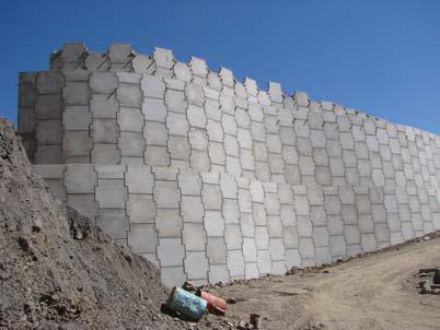
6 Fig.12. Cutting In each sequence, leveling pad concrete was poured after cutting steps. The first step of the walls was constructed with steel meshes as facing. Therefore, a strip footing was considered for setting up the steel meshes (Fig. 13). Fig.14. Leveling pad Fig.15. Concrete panel installation Fig.13. Strip footing Next sequences were completed according to the reinforced earth walls construction standards as mentioned below: Concrete panel installation, connecting galvanized steel strip to the panels with respect to horizontal distances and appropriate lengths which had been specified in the design steps, embankment and compaction and installing drainage system as required. These items were carried out sequentially as specified walls heights were reached. Figure 14 to 18 illustrate the walls construction steps. Fig.16. Connecting galvanized strips to concrete panels Paper No.7.04b 5


.")

. In the primary design steps, soil nail walls had been considered for this section.")
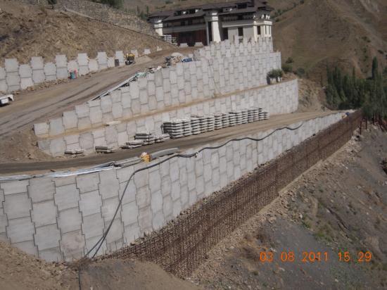
7 Fig.17. Embankment Fig. 19. Steep slope Fig.18. Compaction Construction Problems and Obstacles As mentioned above, the project located in the mountainous area with a lot of geometrical complexities and loose soil in some areas. As expected, the construction in this site had its own problems and was exceptional from other reinforced earth projects. Excavation in the 60 to 70 degrees and 70 meter slope was one of the obstacles, which extensive safety was needed during the construction (Fig. 19). A temporary structure was installed in order to prevent the light equipments and materials from falling down. After the first cutting, a proper platform was made for other sequences. Fig. 20. Temporary structure One of the problems of the project was the dumped materials at the north area which had made a 16 meter trench (Fig. 21). In the primary design steps, soil nail walls had been considered for this section. However, the soil nailing was eliminated after local observations and unsuccessful soil nailing experience on the north neighbor s site. The unstable slope had made the construction condition hard. Cutting of the lower parts was stopped due to uncertainty of this section. Fig.21. Loose dumped materials It was decided that reinforced earth walls should construct Paper No.7.04b 6


8 instead of the soil nail walls considering all options. Gypsum grout was used for temporary protection of exposed soil of the slope (Fig. 22). Fig. 22. Gypsum grout Figure 23 illustrates 3 steps walls which were constructed in this area. Fig. 23. Three steps walls The road curve was another feature of this project which has a 12 meter radius. Dividing the walls heights by 3 steps and reducing the heights of the upper steps made the construction possible. CONCLUSION The conclusions presented here are based on the findings of this study. However, these can be used for other similar projects with engineering judgments: Choosing an appropriate method for slope stabilizing and retaining wall is one of the most effective factors in construction cost in a mountainous area. Reinforced earth structure can be mentioned as a cost effective option in this field. Flexibility, construction rate, economically efficient, lack of a need of a foundation and suitable performance are the main features of reinforced earth method which were considered in the first design step. In order to aesthetic view and economical efficiency, each walls height was divided by several steps. TALREN was used for design in the project. Some critical sections were modeled and the reinforcements were determined with trial and error method. Limitations in the construction as well as satisfying stability condition were considered in the reinforcement determination. Excavation was one of the most challenging steps of the construction. The temporary retaining structure was built for the project safety. The slope in the north area was unstable and several cracks could be seen on the existing road. Dealing with this part was important during the construction. Soil nailing would have been an appropriate option for this part. Although, the dumped materials did not allow to construct the soil nail walls. In addition, the similar experience in another project had failed. The exposed soil of the slope was temporarily stabilized with gypsum grout. Finally, the three steps of reinforced earth walls were constructed in the north area. The 12 to 15 meter curve was another example of the project obstacles. The walls height division was made construction possible. The construction lasted 6 months. Figure 25 shows the construction steps during the 6 months. Fig.24. Reinforced earth walls in the curve Paper No.7.04b 7


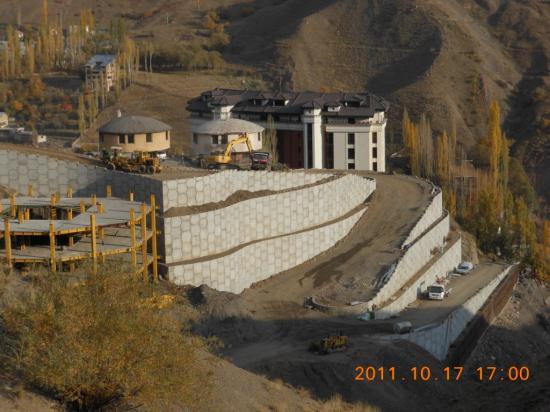
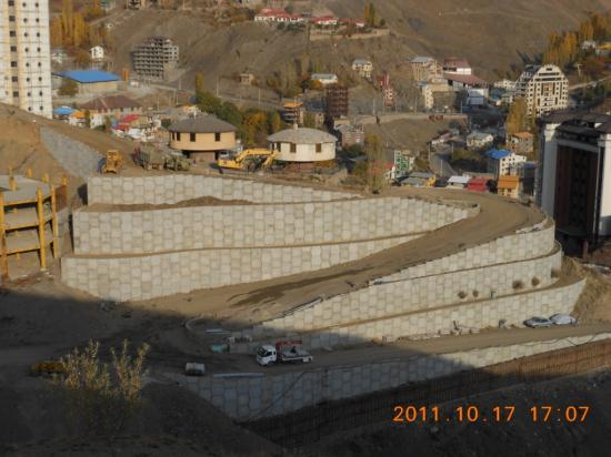
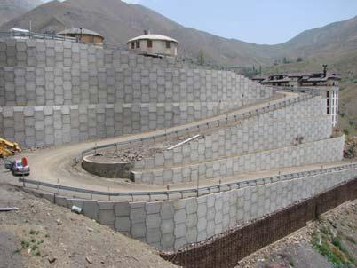
9 Fig.25. Access road of the LARSI building Paper No.7.04b 8
10 REFERENCES Behnia, C., Tabatabai, M., (1987), 'Soil Mechanics Vol. 2", University of Tehran Press. Archive of Reinforced Earth Iran Company. Federal Highway Administration, Design of Mechanically Stabilized Earth Walls and Reinforced Soil Slopes Volume, FHWA-NHI , Washington, D.C. TERRASOL. (2005), TALREN 4 Manual, February 2005 Paper No.7.04b 9