Evaluation of PDA Data to Identify Pile Issues Presented at Annual KC Specialty Seminar January 9, 2015
|
|
|
- Oscar Houston
- 5 years ago
- Views:
Transcription

1 Evaluation of PDA Data to Identify Pile Issues Presented at Annual KC Specialty Seminar January 9, 2015
2 Presentation Topics Overview of PDA data collection Case histories for how PDA testing reduced the risk of installing pile foundations
3 Overview of PDA Data Collection Dynamic testing includes both high-strain and low-strain testing Foundation types tested typically include driven steel or concrete pile and sometimes cast-in-place concrete piles
4 High-strain Dynamic Testing Involves measurement of strain and acceleration near the pile top during driving By knowing material properties of the pile, assessment of pile integrity and capacity is made using principals of 1- dimensional wave mechanics

5
6 Pile Testing Basics Strain gages and accelerometers are mounted on the pile Readings are taken for each blow when triggered by the impact of the hammer anvil on the pile Data are viewed during collection in the field and are post-processed to present plots and more accurate predictions of static capacity
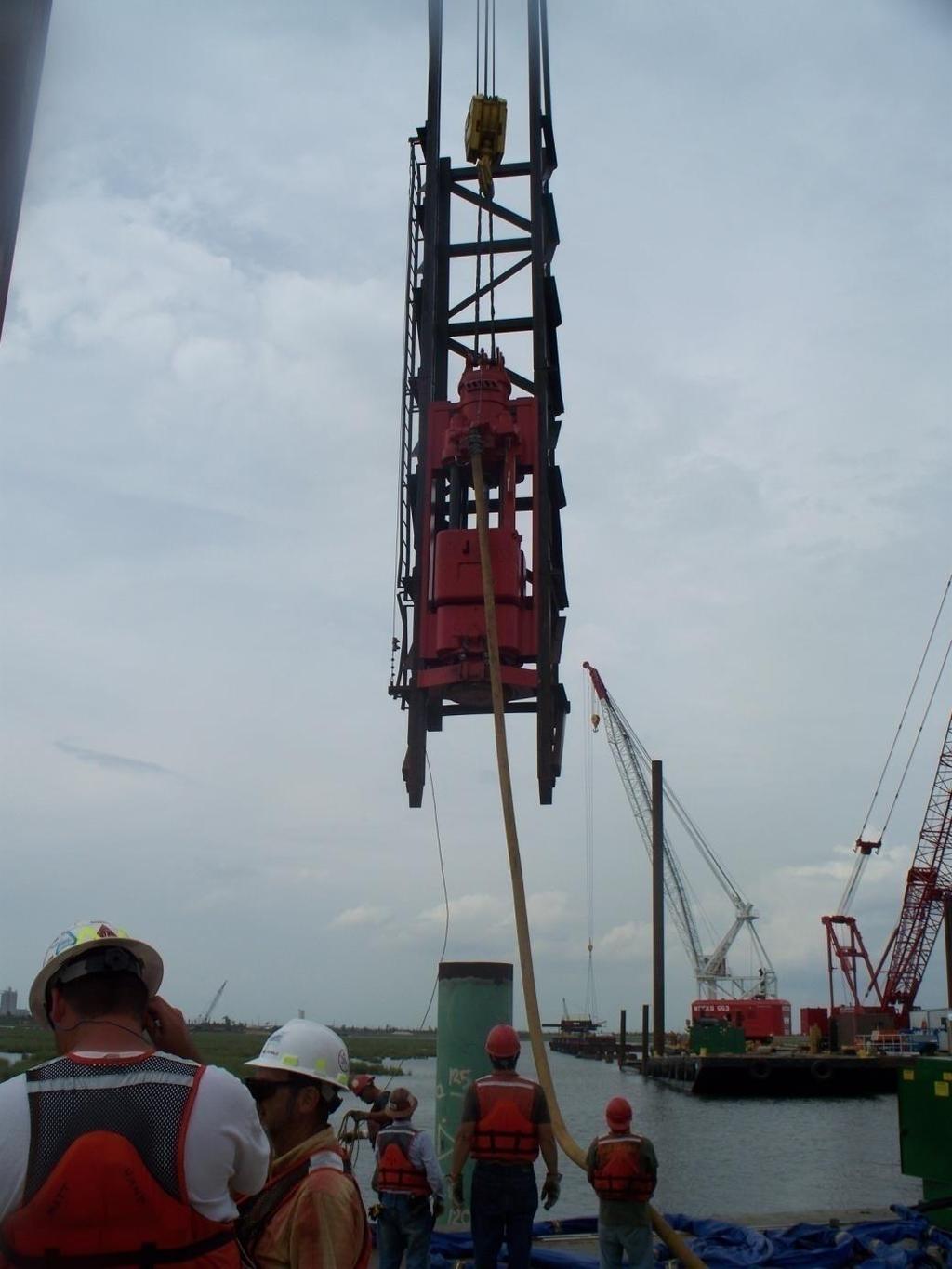
7 Major Components for Pile Driving Test Pile Driving System Measurement system (acceleration, strain at gage location)
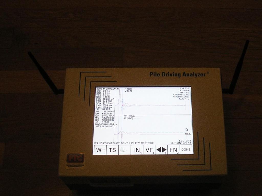
8 Dynamic Pile Testing Measurement Components PDA pile driving analyzer (field computer with specialized software) Strain gages - mount to pile (usually 2 pile diameters or more from top of pile) Accelerometers mount to pile near strain gages Connection between PDA and Gages on Pile (radio or cable)

9
10 Pile Dynamics, Inc. PAX User s Manual November 2008

11

12

13

14
15 Pile Dynamics, Inc. PAX User s Manual November 2008

16
17
18

19
20 Software for Testing PDA pile driving analyzer CAPWAP signal matching software for more accurate capacity prediction WEAP wave equation analysis. Provides for estimation of pile driving system performance and pile stresses prior to installation.
21 Test Program Overview PDA tests are typically conducted at end-ofinitial drive (EOID) and during re-strike tests at various time intervals Installation logs (driving logs) are recorded for all pile to compare hammer stroke and pile set to values recorded for test pile where capacity was measured
22 Potential Pile Testing Goals for Risk Mitigation When should driving stop to ensure required axial capacity is developed? How should capacity be verified for subsequent production piles? How should driving be performed to avoid pile damage? What time-dependent capacity changes could be expected?
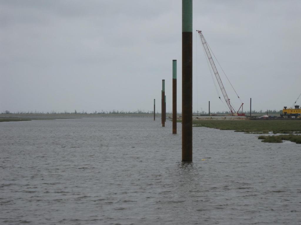
23 Project Example Inner Harbor Navigation Canal Floodwall 36-inch diameter steel pipe pile 66-inch diameter concrete pile Project located in New Orleans Typical Water Depth of 20 feet Soft Silty Clays and Loose Sands

24

25

26
27 Inner Harbor Navigation Canal Floodwall Indicator Pile Program 36-inch diameter steel pipe pile, 130 feet long Drove test pile in advance along the project alignment Performed PDA tests at initial drive and various re-strike intervals for test pile
28

29
30

31
32 Typical Results for 36-inch Steel Pipe Pile Capacity at end of initial drive (EOID) Capacity at various re-strike intervals Resistance Distribution
33
34
35 Capacity (kips) vs. Time (minutes) - All Piles Pile 9 Pile 8 Pile 7 Pile 6 Pile 5 Pile 4 Pile 3 Pile 2 Pile 9A
36 36-inch Steel Pipe Pile Testing Conclusion Target Capacity was reached at 5 to 7 days following installation as planned Capacity at 1 week was 3 to 5 times EOID capacity Early re-strikes (less than 3 days) under predicted longer term capacity trend
37 66-inch Concrete Pipe Pile Raymond 60X (150 kip-ft) Steam Hammer Bruce Hydraulic Hammer (282 kip-ft) 14 inch thick plywood cushion Stress Limits for compression and tension in concrete were 3.4 ksi and 1.3 ksi, respectively
38
39 Graves County, Kentucky Project 18-inch diameter steel, ½-inch wall pipe pile with conical tip Total pile length of 85 feet with splice at a depth of 40 feet below pile top Piles subject to initial drive and 6 day restrike testing

40
41
42

43
44
45 Springfield, Missouri Project HP10X42 pile, 50 ksi steel Total pile length of 30 feet with driven 9 feet below grade Stiff Clay soil profile overlying hard dolomitic limestone Required Axial Capacity of 259 kips
46
47

48 H-Pile in Kansas for Bridge Abutment
49 Project Details HP 10 X 42 Pile Plan Length 73 feet per pile Required Ultimate Capacity (350 Kips) 30 feet of compacted clay fill over 50 feet of stiff to hard silty clay

50 Soil Profile at Bridge Site
51
52 Results Summary Test Pile EOID Capacity 1 Hour Restrike Capacity 16 Hour Restrike Capacity 084 Abutment No. 1 (Pile 620) 244 kips 405 kips 613 kips
53 Conclusions about Re-strike Tests for Piles in Alluvium Short-term re-strike intervals (a few hours to a day) may be sufficient to document significant capacity increase Longer term re-strikes (1 week) may result in difficulty in adequately mobilizing pile (under predicts capacity)
54 Project Details Expansion of Existing Building 24 inch Square Pre-cast, Pre-stressed Concrete Pile Pile Length of 49 feet, 42 foot driven depth Limiting Driving Stress were 0.95 ksi in Tension and 2.6 ksi in Compression. Required capacity of 296 kips
55 Project Details Concrete piles are seldom used in NE Oklahoma (H-pile is common) Most borings were terminated at a depth of 15 feet with only a few extended to 25 feet. Pile had a pre-drilled depth of 18 feet. Existing building onsite was occupied during construction.

56 Project Details Before Changing Pile Cushion After Changing Pile Cushion
57
58 What is Refusal Pile to be driven to a set of 1 inch or less in 10 blows? Pile to be driven to a set of 1 inch or less in 20 blows? What is the corresponding hammer ram stroke for these refusal criteria?
59 Project Details HP10X42 Pile with driving tips, 50 ksi steel Required capacity of 550 kips!!! Pile to develop capacity after driving to rock? No dynamic pile testing was originally planned at project.
60
61
62
63
64
65


66
67 Hammer Ram Stroke (Open-end Diesel Impact Hammers) Typical recording Methods Estimated based on observation of length of ram extending from top of hammer Calculated based on elapsed time Recorded as part of high-strain dynamic testing - calculated based on elapsed time between triggered events (blows) Recorded using Saximeter
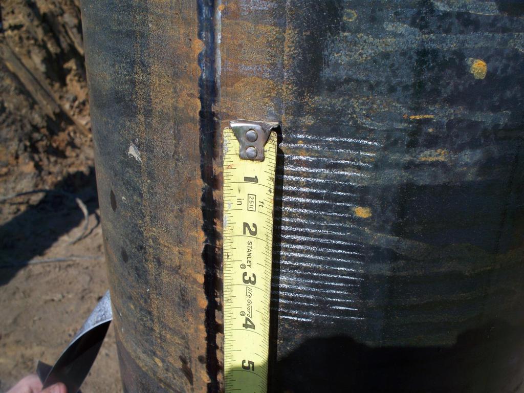
68 Pile Set Monitoring
69 FTC Developed the Laser-Based Automated Pile Set Monitor for the following reasons Permit accurate recording of penetration per blow without placing a worker near the pile during driving Permit Calculation of Ram Stroke Allow Confirmation of Driving Criteria Store Results Electronically with Output in Tabular and Plotted Formats for Viewing and Printing


70 Pile Set Monitor

71 Pile Set Monitor

72 Pile Set Monitor

73

74

75

76

77
78
79
80 Guidance for Performing Dynamic Pile Testing Permits use of higher resistance factors Ability to confirm adequacy of pile hammer Ability to confirm installation parameters to avoid under-driving, over-driving or damaging piles
81 Guidance for Performing Dynamic Pile Testing Restrike testing can permit more efficient pile foundations in many situations (or prevent time dependent problems) Can alert crew to change in subsurface conditions
82 Contact Information Casey Jones, P.E, P.G