Equilibrium. Of a Rigid Body
|
|
|
- Alexia Stevenson
- 5 years ago
- Views:
Transcription

1 Equilibrium Of a Rigid Body 1
2 Objectives 1. To develop the equations of equilibrium for a rigid body. 2. To introduce the concept of the free-body diagram for a rigid body. 3. To show how to solve rigid body equilibrium problems using the equations of equilibrium. 2
3 Part A 3
4 Conditions for Rigid-Body Equilibrium F 0 0 M / A 4
5 2D Supports 5
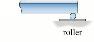
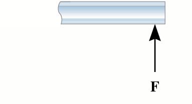
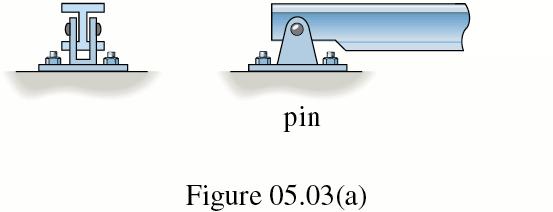
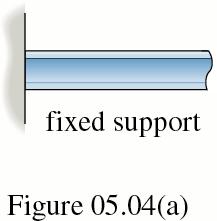
6 Support Reactions General Rule: If a support prevents the translation of a body in a given direction, then a force is developed on the body in that direction. Likewise, if rotation is prevented a couple moment is exerted on the body. 6
7 7
8 8
9 9
10 Rocker 10

11 Smooth Surface 11

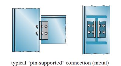
12 Pinned or Hinged 12
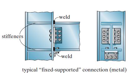
13 Fixed 13
14 Drawing a Free-Body Diagram 14

15 Modeling 15

16 Modeling 16
17 Procedure for Drawing a Free- Body Diagram 1. Select co-ordinate axes. 2. Draw outlined shape isolated or cut free from its constraints and connections. 3. Show all forces and moments acting on the body. Include applied loadings and reactions. 4. Identify each loading and give dimensions. Label forces and moments with proper magnitudes and directions. Label unknowns. 17
18 Free Body Diagrams 18
19 Free Body Diagrams 19
20 Important Points 1. Equilibrium problem should be solved by draw the appropriate F.B.D. 2. If a support prevents translation in a direction, then it exerts a force on the body in that direction. 3. If a support prevents rotation of the body then it exerts a moment on the body. 20
21 Important Points 1. Couple moments are free vectors and can be placed anywhere on the body. 2. Forces can be placed anywhere along their line of action. They are sliding vectors. 21
22 Part B 22
23 Beams, Trusses, Frames and Cables Structure: Equilibrium in two dimensions 23
24 Types of Structures A structure refers to a system of connected parts used to support a load. Important examples related to civil engineering include buildings, bridges, and towers; and in other branches of engineering, ship and aircraft frames, etc. 24
25 Classification of Structures 1. Structural Elements: Some of the more common elements from which structures are composed are as follows: I. Tie Rods: Structural members subjected to a tensile force are often referred to as tie rods or bracing struts 25

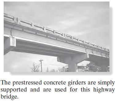
26 II. Beams: Beams are usually straight horizontal members used primarily to carry vertical loads. 26
27 27
28 28

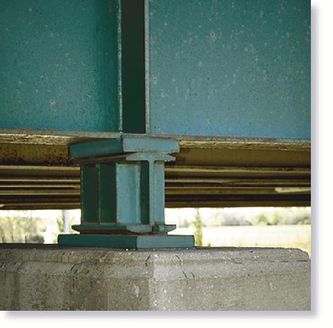
29 III. Columns: Members that are generally vertical and resist axial compressive loads are referred to as columns 29
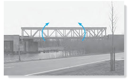
30 2. Types of Structures: The combination of structural elements and the materials from which they are composed is referred to as a structural system. Each system is constructed of one or more of four basic types of structures. I. Trusses: When the span of a structure is required to be large and its depth is not an important criterion for design, a truss may be selected. Trusses consist of slender elements, usually arranged in triangular fashion. Planar trusses are composed of members that lie in the same plane and are frequently used for bridge and roof support. 30
31 31

32 Roof Truss 32

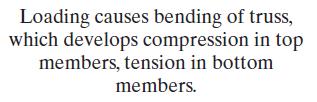
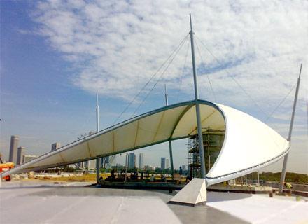
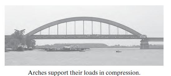
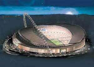
33 II. Cables and Arches: Two other forms of structures used to span long distances are the cable and the arch. Cables are usually flexible and carry their loads in tension. They are commonly used to support bridges, and building roofs 33
34 34
35 35
36 36

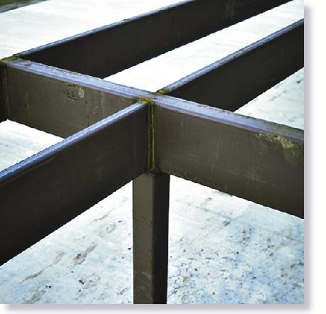
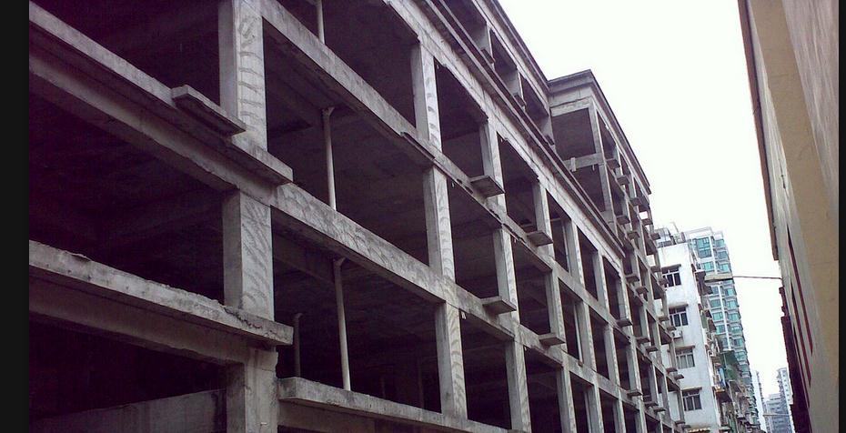
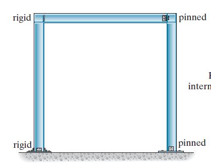
37 III. Frames: Frames are often used in buildings and are composed of beams and columns that are either pin or fixed connected. 37
38 38

39 39


40 2D Equilibrium Scalar Equations F x 0 F y 0 M O 0 40
41 Procedure for Analysis 1. Free-Body Diagrams 2. Equations of Equilibrium 41

42 Example Determine the reactions at the supports. 42
43 43
44 Equations of Equilibrium Fx 0; 600cos 45 N Bx 0 Bx 424N M 100N(2m) (600sin 45 A y B 0; 319N N)(5m) (600cos 45 N)(0.2m) A y (7m) 0 F y 0; 319N 600sin 45 B y 405N N 100N 200N B y 0 44
45 Example Determine the reactions at the supports. 45
46 46
47 B x x y y M x y A 0 ( ccw) 90N m (60N) (1m) (N ) (0.75m) 0 N 200N F 0 A 200sin 30 0 A 100 N F 0 A 200cos A 233N o o B 47

48 Example Determine the reactions at the supports. 48
49 49

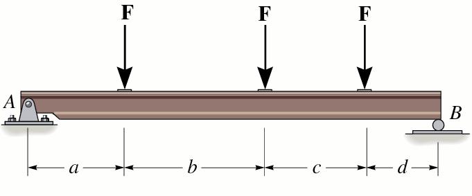
50 Example 1: For the beams shown in Fig.(1) and (2). I. Determine the resultant force and specify where it acts on the beam measured from A. II. Determine the support reactions. Fig.(1) 50
51 Fig.(2) 51
52 Example 2: Determine the support reactions for the structures shown in Fig. (3) to (5). Fig.(3) 52
53 Fig.(4) 53
54 Fig.(5) 54