Structural Technical Report I October 5, 2006 Structural Concepts / Structural Existing Conditions Report
|
|
|
- Coral Harper
- 5 years ago
- Views:
Transcription

1 1 THE ODYSSEY ARLINGTON, VA Aaron Snyder Structural Option Advisor: M. Kevin Parfitt, PE Structural Technical Report I October 5, 2006 Structural Concepts / Structural Existing Conditions Report Executive Summary: The Odyssey is a 475,650 SF luxury residential complex located in Arlington, Virginia. It features 2-3 story townhouses adjacent to 3 levels of underground parking and towers clad with glass curtain walls and brick. There are 16 stories of apartments with suites located on the top floors and retail space on the ground floors. In this first technical report the existing structural conditions of the Odyssey are introduced through detailed descriptions of the foundation, floor, column, and lateral systems. A preliminary analysis of design loads and lateral forces are spot checked on a typical column and shear wall for discrepancies in design criteria. The analyses provide better understanding into loading and code assumptions made through ASCE7-02 provisions. The wind analysis was carried out under ASCE7-02 section 6 with general building assumptions including disregarded façade curvature and overall rectangular dimensions. The preliminary analysis resulted in an unbalanced leeward to windward wind ratio which may be a result of the preliminary assumptions. A further detailed analysis is required to obtain a specific controlling wind direction and resulting loading envelope. A seismic analysis was carried out under the equivalent lateral force procedure specified in section 9 of ASCE7-02. All seismic factors were chosen through design parameters based upon the building characteristics and location. As a result of the analysis the controlling seismic direction is E-W with a base shear of 2045k. Design checks upon both gravity and lateral systems were carried out to verify the accuracy of loading assumptions made through code provisions. The 2-way posttensioned flat slab system was determined acceptable to resist slab moments from typical floor live and dead loads on a typical residential level of the Odyssey. Through the preliminary analysis the slab stresses resulting from post-tensioning maintained values within the ultimate stresses. A column located on the 1 st level was spot checked to ensure the design reinforcement was adequate to resist accumulated gravity loads over the remaining levels. The loading on the column corresponded closely to given design column load of 2180k and the 12 -#11 bar reinforcement was found adequate up to 2340k. An analysis of the lateral systems will be addressed in the Lateral Systems Analysis and Confirmation Design report. Analysis calculations and observations are found in Appendices A - E as well as descriptive figures of preliminary structural design components and a typical floor plan.


2 2 Structural Systems: Foundation The primary foundation structures of the Odyssey are concrete footings of various rectangular sizes, depths, and reinforcement throughout the lower garage level footprint. Individual column footings are typical; however 54 deep mat footings distribute larger gravity loads and resist overturning from several integrated shear walls. The primary mat foundation spans over numerous columns which support shear walls beginning on the 1 st floor of the building. A second mat footing resists the lateral overturning through core shear walls located around the central elevator shafts depicted in a partial foundation plan shown to the right. Continuous strip footings typically sized at 2-0 x 1-4 and support a perimeter bearing wall surrounding the lower garage levels. Floor Systems The floor systems found throughout the Odyssey seemingly vary as much as the space usage in the building. Three distinct systems are noted in the following sections due to size, loading, and use of the supported space: Sub-Level Garage: The lower garage level (B3) is composed of 4 concrete slab (f c=5ksi) on grade and reinforced with 6x6 w1.4 x w1.4 wire mesh on 6mil vapor barrier over 6 compacted gravel with a capacity of 5,500psf. The remaining lower garage levels through the first floor are primarily 8.5 conventionally reinforced 2-way concrete flat slabs with bottom reinforcement of #4 13 o.c. Additional top and bottom reinforcement is specified as needed throughout the floor with varying bar sizes at specified spacing. Drop panels are located at specified columns and typically extend 4-1/2 below slab with several panels up to 6-1/4 to 8 below the slab. Also found on these floors are reinforced edge beams around larger spans for loading docks, mechanical spaces/shafts, and retail space located on both the upper garage and 1 st floors. Typical bays sizes for the reinforced 2-way slab system are 25 x25 and 17 x25.


3 3 Tower: 2 nd 15 th The Odyssey tower is primarily an 8 2-way post tensioned flat concrete slab (f c=5ksi) with continuous bottom reinforcement of #4 24 o.c in each direction. Negative moment reinforcement of the slab at column junctions is typically #4 bars expanding.33l n in both span directions. Added reinforcement at slab openings in the long direction of specified bays is also typically #4 bars. Post tensioning tendons are 7 wire strands spanning columns and mid spans on a typical frame. Floor bays vary in size but 25 x 22 and 25 x 28 are typical with a variation on the 14 th floor that has post tensioned beams integrated into the 2-way slab to support the rooftop swimming pool. (See Appendix A for a typical floor plan of the 2 nd 15 th levels of the Odyssey) 16 th & Roof The roof and upper floor system of the western portion of the Odyssey s tower is similar to that of the lower floors, however reinforced concrete edge beams and interior post tensioned beams were included to properly support excess loads from mechanical equipment. Sizes and reinforcement vary between beams and post tension loading varies depending on span and location in the system. The east tower on the 16 th level support the pool terrace and is a 11 2-way post tensioned flat slab(f c=5ksi) with #5 24 o.c. each way and specified areas with added bottom reinforcement typically #5 and #6 bars. Typical floor bay sizes vary with 25 x 22 and 25 x 28 most common throughout these levels. Townhouses Townhouses which span the length of the site on the east are built integrally with the lower garage levels but do not share the same floor system. The system is 8.5 one-way concrete slab conventionally reinforced with #4 13 o.c. and built-in reinforced edge beams typically 24 x18 and 26 x16 with #6 and #11 reinforcement. Two floor bay sizes are split between the townhouses with 23 x 30 and 19 x 30 spanning the edge beams. The townhouse roof system is also split over the row with the typical one-way concrete slab or cantilevered 12 metal 24 o.c. with metal soffit. Columns: Structural columns of the Odyssey are primarily a simple concrete structure with varied sizes, shapes, and reinforcement dependent on level and location throughout the building. The columns found in the tower of the Odyssey, levels 1-16, support the floor systems and are typically sized at 18 x 26 with #11 bar reinforcement. Round columns are found at the corners of the tower with primarily architectural design influences to not detract from symmetric corner windows with conventional rectangular columns integrated into apartment walls.
4 4 The columns located in the lower garage through 1 st levels, and partially on 2 nd and 3 rd levels, serve a dual purpose in the structural design of the Odyssey. Rotated columns are oriented differently at floor slabs, typically rotating 90 from underside to the top side of the floor slab. These columns support the floor systems and are an architectural design to better fit apartment spaces. Sloping columns are oriented differently from face to face of the slab on the same level. The purpose of these sloping columns is to effectively transmit lateral loads from shear walls and the building edge into the foundation. A further look into the integrated functioning of sloping column and foundation in regard to lateral distribution and moment may provide better analysis of the structures behavior. Both types of columns vary in size with a range in sizes from 18 x 26 to 26 x 42 with #11 bar reinforcement. Column concrete strengths vary by level to resist accumulated gravity loads: Levels B3-B1 : f c = 6000psi Levels 1-4 : f c = 8000psi Levels 5 : f c = 6000psi Levels 6-16 : f c = 5000psi Lateral System: The lateral resisting systems of the Odyssey are groupings of shear walls placed throughout the floor plan integrated with slab frames. Locations on the exterior wings provide single lateral direction bracing while those at the core provide resistance in both primary directions. The shear walls are depicted below in simplified plans with a generalized description of each wall. (See Appendix-A for a typical floor plan and shear wall distribution) Shear wall A: Resists both lateral load directions: North-South & East-West. Location: Surrounds 2 central-north elevator shafts Range: B3-4 th level Size: North-South walls x 10 Integrated into columns - 14 x 28 Column Reinforcement 6 #9 bars East-West wall 10 x17-10 Wall Reinforcement: #5 & #6 12 Shear wall B: Resists both lateral load directions: North-South & East-West. Location: Surrounds 2 central-south elevator shafts Range: B3-4 th level Size: North-South walls x 10 Integrated into columns - 14 x 28 Column Reinforcement 6 #9 bars East-West wall 10 x17-0 Wall Reinforcement: #5 & #6 12
5 5 Shear wall C, C1: Resists lateral load directions: North-South Location: Surrounding West stair tower. Range: 1st - 16 th level C1 terminates at 10 th level Size: North-South walls - 10 x Ends attached to columns 18 x 26 and 24 x 24 Column Reinforcement (varies) #11 bars Wall Reinforcement: #5 & #6 12 Shear wall E: Resists lateral load directions: North West-South East Location: Column line X4 - North side of East tower Range: 1st - 14 th level Size: North-South walls - 10 x 29-5 Ends attached to columns 18 x 26 Column Reinforcement (varies) #11 bars Wall Reinforcement: #5 & #6 12 Codes and Requirements: The Odyssey is designed under: The 1996 BOCA National Building Code The 1996 Virginia Uniform Statewide Building Code with 2000 Amendments Concrete construction in accordance with: American Concrete Institute 318 Reinforced Concrete Design American Concrete Institute 301 Specification for Structural Concrete Building Officials and Code Administrators (BOCA) Latest Edition Steel construction in accordance with: Building Officials and Code Administrators (BOCA) American Institute of Steel Construction Manual Allowable stress design (ASD) Masonry construction in accordance with: Building Officials and Code Administrators (BOCA) Building Code Requirements for Masonry Structures and Specifications for Masonry Structures ACI-530 / ACI Material strength and details in accordance with: ASTM Standards Properties of Building Materials
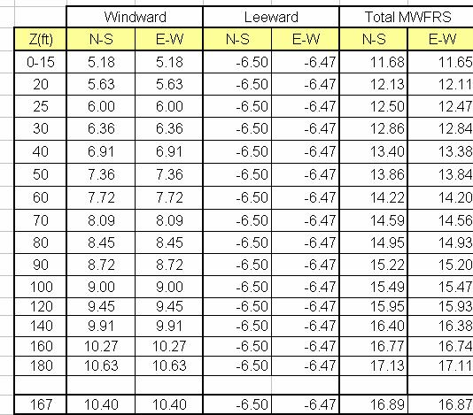
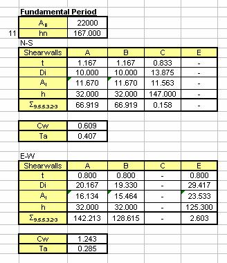
6 6 Gravity and Lateral Loads: The gravity and lateral loads for structural analysis were determined in accordance with ASCE7-02. General assumptions for several dead loads were made with interpretation of details and structural component averages. Load factors and adjustments are used when appropriate according to provisions of ASCE7-02 for the analysis of structural components and systems. A list of relevant gravity loads follow: Gravity: (psf) Floor Live: Residential Units & Corridors 40 Public Areas 100 Mech. Room 150 Pool Terrace 100 Parking Garage 50 Stairs and Exits 100 Roof Live: Min. Roof Live Load 30 Roof Snow: Roof Snow Load 21 Floor Dead: Concrete Slab (varied thickness 8-12 ) Partitions 8 Flooring 4 Ceiling 5 Mechanical 10 Beams/Columns (* varies) Lateral: A summary of lateral loads calculated in accordance with ASCE7-02 design provisions are presented in the following sections. Refer to Appendices B & C for further detailed procedure and analysis of calculations including generalized assumptions. Wind: ASCE7-02 Section 6 Wind loads were determined for the Odyssey under the analytical procedure of Section 6, ASCE7-02. General assumptions for the preliminary analysis include simplifying the Odyssey s irregular shape into a general rectangular dimension for accordance of shape limitations set forth by the analytical procedure. Analysis factors were determined through ASCE7-02 references and are detailed in the analysis located in Appendix-B. The factors are dependent on building location, characteristics, and predetermined factors outlined on the structural prints. Building rigidity of both wind loading directions were found to be rigid through generalized and detailed analysis of the fundamental period. (The fundamental period calculation is found in Seismic Analysis section: Appendix C)

 Seismic: ASCE7-02 Section 9 Seismic loads were determined through the equivalent lateral force procedure outlined in Section 9 of")
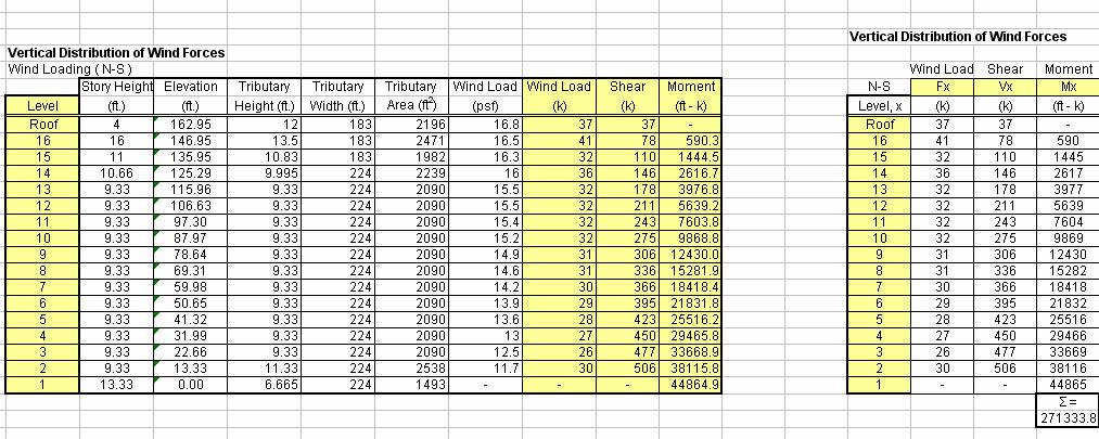
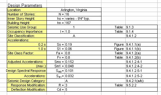
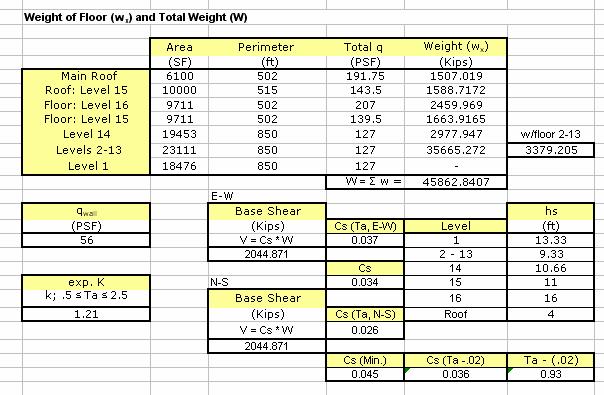
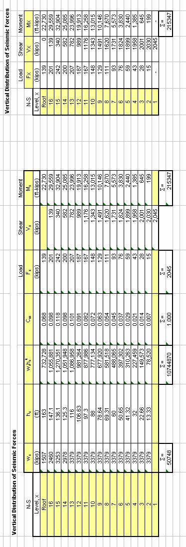
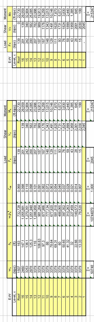
7 7 The windward pressures found through the analytical procedure are low by a comparison ratio to the leeward pressure. Discrepancies in procedure or calculation errors were unable to be found upon review of the analysis. Further investigation into wind loading will be dealt with in a later technical report regarding lateral design. The wind loading was determined not to control the lateral design of the Odyssey. Wind Pressure Envelope N-S Distribution (Controlling direction) Seismic: ASCE7-02 Section 9 Seismic loads were determined through the equivalent lateral force procedure outlined in Section 9 of ASCE7-02. All relevant factors and accelerations were found in figures and tables of section 9, which are outlined in the seismic analysis section located in Appendix C. Building and floor weights are based on assumptions of design dead loads according to load provisions of ASCE7-02. The base shear was 2045 kips in both loading directions with an overturning moment of ft-k. The base shear to building weight ratio is approximately 4%. The analysis results can be considered acceptable for a low seismic region. Vertical Distribution of Seismic (E-W)
8 8 E-W Distribution Preliminary Analysis / Spot Check Summary: Gravity Post-Tensioned 2-way Concrete Slab: A preliminary structural analysis of a 8 2-way post-tensioned concrete flat slab was carried out under generalized assumptions to better understand the design effects of post-tensioning reinforcement. A typical floor bay was determined to be 25 x 22 excluding the edge panel balcony sections. Slab moments were resolved for residential and corridor live loads with standard dead loads for typical residential levels. Slab moments and calculations can be referenced in Appendix D. Standard top and bottom slab reinforcement of #4 bars was analyzed for resisting the slab moments and was inadequate in mid span and support strips. As a result, post tensioning is required through the slab to maintain an 8 depth with minimal #4 bar reinforcement. The designed 7 wire strand reinforcing tendons are tensioned to 509k in the long frame direction over columns, and 1300k in the short direction through the mid span. The post tensioning analysis was carried out by calculating the slab stresses at both service and initial loading stages and then compared to the ultimate slab stresses. The post tensioning design was adequate to resist the slab moments with resulting stress calculations maintained within initial and service stresses. (Details of calculations and findings of the post tensioned slab analysis are found in Appendix E)
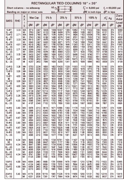
9 9 Column: The structural spot check was carried out with a typical 18 x26 column on the 1 st level of the Odyssey. The column has a tributary area of 625 S.F. and is located at the intersection of column lines F & 7.5. Gravity loads of the remaining levels were calculated to the column including typical floor and roof loads. The axial load resolved on the column was 2162k, which is reasonable for design assumptions of building loads compared to the actual 2180k on the column. The CRSI Design Handbook was used to reference the adequate column reinforcement for a 18 x26 column with design strength of f c = 8ksi. The given reinforcement of 12 - #11 bars is capable of carrying a design load of 2340k. The typical reinforcement design size in columns throughout the building is determined adequate by spot check requirements for loading assumptions and provisions of ASCE7-02. Lateral Shear Wall: Due to the complexity of the lateral systems, the analysis and spot check of the shear walls will be addressed in the Lateral Systems Analysis and Confirmation Design report. Conclusions/Summary: The Odyssey is a multifaceted building including underground parking, retail stores, and 15 levels of residential apartments/condominiums. The existing gravity structural system is 2-way post tensioned flat slab for residential levels and 2-way flat slab with drop panels for the parking levels. The lateral systems are shear walls located at the building core and on the exterior wings integrated with slab frames composed of the concrete columns and 2-way flat slab floor system. Lateral loads were determined in accordance with provisions and design procedures of ASCE7-02 and it was found that seismic loads control the Odyssey s lateral design. Design checks upon both gravity and lateral systems were carried out to verify the accuracy of loading assumptions made through code provisions. The 2-way posttensioned flat slab system was determined acceptable to resist slab moments from typical floor live and dead loads on a typical residential level of the Odyssey. Through the preliminary analysis the slab stresses resulting from post-tensioning maintained values within the ultimate stresses. A column located on the 1 st level was spot checked to ensure the design reinforcement was adequate to resist accumulated gravity loads over the remaining levels. The loading on the column corresponded closely to given design column load of 2180k and the 12 -#11 bar reinforcement was found adequate up to 2340k. An analysis of the lateral systems will be addressed in the Lateral Systems Analysis and Confirmation Design report. Analysis calculations and observations are found in Appendices A - E as well as descriptive figures of preliminary structural design components and a typical floor plan.
10 10. Appendix Appendix A Floor Plan Appendix B Wind Analysis Appendix C Seismic Analysis Appendix D Snow Load Appendix E Gravity Load Check References: CRSI Design Handbook 2002 ASCE7-02 Design Code
11 11 Appendix A FLOOR PLAN F 7.5
12 12 Appendix B WIND ANALYSIS
13 13
14 14
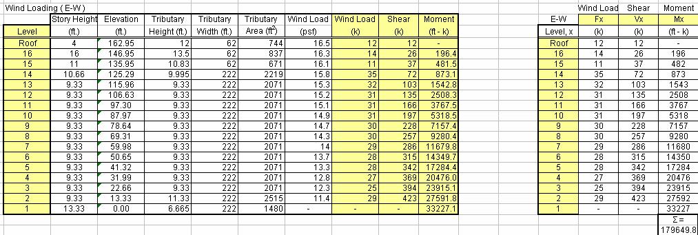
15 15 N-S Distribution Wind Direction E-W Distribution Wind Direction
16 16 Appendix C SEISMIC ANALYSIS
17 17
18 18
19 19
20 20
21 21 N-S Distribution E-W Distribution
22 22 Appendix D SNOW LOAD
23 23 Appendix E GRAVITY LOAD CHECK
24 24
25 25
26 26
27 27
28 28