GEOTEK ENGINEERING & TESTING SERVICES, INC. 909 East 50 th Street North Sioux Falls, South Dakota Phone Fax
|
|
|
- Marilynn Powell
- 5 years ago
- Views:
Transcription
1 GEOTEK ENGINEERING & TESTING SERVICES, INC. 909 East 50 th Street North Sioux Falls, South Dakota Phone Fax May 10, 2016 Banner Associates, Inc W. 57 th Street, Suite 102 Sioux Falls, South Dakota Attn: Kristin Bisgard Subj: Geotechnical Exploration Proposed Meter Building Lewis & Clark Regional Water System 250 th Street & Edwards Avenue Near Adrian, Minnesota GeoTek # This correspondence presents our written report of the geotechnical exploration program for the referenced project. Our work was performed in accordance with your authorization. We are transmitting an electronic copy of our report for your use. We thank you for the opportunity of providing our services on this project and look forward to continued participation during the design and construction phases. If you have any questions regarding this report, please contact our office at (605) Respectfully Submitted, GeoTek Engineering & Testing Services, Inc. Jared Haskins Jared Haskins, PE (SD) Geotechnical Manager Matthew Thompson Matthew Thompson, PE (MN) Project Manager
2 Proposed Meter Building Page 2 of 17 TABLE OF CONTENTS INTRODUCTION... 4 PROJECT INFORMATION... 4 SCOPE OF SERVICES... 4 SITE & SUBSURFACE CONDITIONS... 5 SITE LOCATION & DESCRIPTION... 5 GROUND SURFACE ELEVATIONS & TEST BORING LOCATIONS... 5 SUBSURFACE CONDITIONS... 5 WATER LEVELS... 6 ENGINEERING REVIEW & RECOMMENDATIONS... 6 PROJECT DESIGN DATA... 6 DISCUSSION... 6 SITE PREPARATION... 7 FOUNDATION LOADS & SETTLEMENT... 7 FLOOR SLAB... 8 DEWATERING... 8 BACKFILLING/LATERAL PRESSURES BELOW-GRADE & RETAINING WALLS... 8 FROST PROTECTION... 9 VEHICLE AREAS... 9 MATERIAL TYPES & COMPACTION LEVELS EXCAVATION COEFFICIENT OF FRICTION DRAINAGE PERCOLATION TESTS CONSTRUCTION CONSIDERATIONS GROUNDWATER & SURFACE WATER DISTURBANCE OF SOILS COLD WEATHER PRECAUTIONS EXCAVATION SIDESLOPES OBSERVATIONS & TESTING EXCAVATION TESTING SUBSURFACE EXPLORATION PROCEDURES TEST BORINGS & PERCOLATION TESTS SOIL CLASSIFICATION WATER LEVEL MEASUREMENTS LABORATORY TESTS LIMITATIONS STANDARD OF CARE... 17
3 Proposed Meter Building Page 3 of 17 APPENDIX A FIGURE 1 PROJECT LOCATION MAP FIGURE 2 SITE MAP BORING LOGS SOILS CLASSIFICATION SYMBOLS AND DESCRIPTIVE TERMINOLOGY
4 Proposed Meter Building Page 4 of 17 GEOTECHNICAL EXPLORATION PROPOSED METER BUILDING LEWIS & CLARK REGIONAL WATER SYSTEM 250 TH STREET & EDWARDS AVENUE NEAR ADRIAN, MINNESOTA GEOTEK # INTRODUCTION Project Information This report presents the results of the recent geotechnical exploration program for the proposed meter building for the Lewis & Clark Regional Water System near Adrian, Minnesota. Scope of Services Our work was performed in accordance with the authorization of Tim Conner with Banner Associates, Inc. The scope of work as presented in this report is limited to the following: 1. To perform two (2) test borings using direct-push methods to gather data on the subsurface conditions at the project site. 2. To perform six (6) percolation tests in the proposed drain field area. However, due to shallow groundwater and caving soils, we were unable to prepare the test holes. 3. To perform laboratory tests that include moisture content, dry density, Atterberg limits (liquid and plastic limits) and unconfined compressive strength. 4. To prepare an engineering report that includes the results of the field and laboratory tests as well as our earthwork and foundation recommendations for design and construction. The scope of our work was intended for geotechnical purposes only. This scope of work did not include determining the presence or extent of environmental contamination at the site or to characterize the site relative to wetlands status.
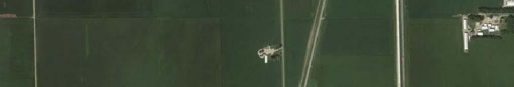
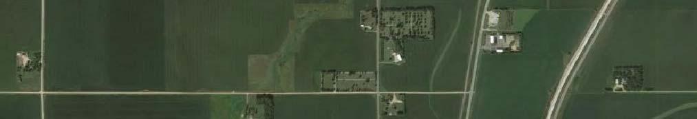
5 Proposed Meter Building Page 5 of 17 SITE & SUBSURFACE CONDITIONS Site Location & Description The project site is located southwest of the intersection of 250 th Street and Edwards Avenue, which is approximately three (3) miles east of Adrian, Minnesota. A project location map is attached at the conclusion of this report showing the location of the site. The site was previously used for agricultural purposes. The topography of the site slopes downward to the northwest. Ground Surface Elevations & Test Boring Locations The ground surface elevations at the test boring locations were estimated from a topographical map provided by Banner Associates, Inc. Based on the topographical map, we estimated the ground surface elevations at the test boring locations to be 1,589.3 feet at test boring 1 and 1,588.1 feet at test boring 2. A site map is attached at the conclusion of this report showing the relative location of the test borings. Subsurface Conditions Two (2) test borings were performed at the project site on May 6, The subsurface conditions encountered at the test boring locations are illustrated by means of the boring logs included in Appendix A. The subsurface conditions encountered at the test boring locations consisted of 2 feet of topsoil materials overlying coarse alluvium soils and glacial till soils. The topsoil materials consisted of lean clay soils. The coarse alluvium soils consisted of sand soils. The glacial till soils consisted of sandy lean clay soils. We wish to point out that the subsurface conditions at other times and locations at the site may differ from those found at our test boring locations. If different conditions are encountered during construction, it is important that you contact us so that our recommendations can be reviewed.
6 Proposed Meter Building Page 6 of 17 Water Levels Measurements to record the groundwater levels were made at the test boring locations. The time and level of the groundwater readings are recorded on the boring logs. Groundwater was measured at depths of 2 feet (elevation 1,587.3 feet) at test boring 1 and 1 ½ feet (elevation 1,586.6 feet) at test boring 2. ENGINEERING REVIEW & RECOMMENDATIONS Project Design Data We understand that the project will consist of constructing a new meter building for the Lewis & Clark Regional Water System near Adrian, Minnesota. The new meter building will be a slab-ongrade structure with a footprint area of approximately 1,000 square feet. We assume that the finished floor of the meter building will be near elevation 1,591.0 feet. We also assume that foundation support for the meter building will be provided by perimeter footings resting below frost depth and interior footings resting at or slightly below the floor slab. Light foundation loads are expected for the meter building. The information/assumptions detailed in this section of the report are important factors in our review and recommendations. If there are any corrections or additions to the information detailed in this section, it is important that you contact us so that we can review our recommendations with regards to the revised plans. Discussion Typically, spread footings are the most cost effective type of foundation system. It is our opinion that a spread footing foundation system can be used for support of the proposed meter building after the recommended site preparation has been performed. It is our opinion that the topsoil materials are not suitable for support of the footings or floor slab of the proposed meter building.
7 Proposed Meter Building Page 7 of 17 Site Preparation The site preparation for the entire footprint of the meter building should consist of removing the topsoil materials in order to expose the coarse alluvium soils or glacial till soils. If the excavation required to expose the coarse alluvium soils or glacial till soils extends below the bottom-offooting/bottom-of-slab elevation, then we recommend placing and compacting structural fill up to the bottom-of-footing/bottom-of-slab elevation. The final 6 inches of fill beneath the floor slab should consist of select granular fill. Please refer to Table 1 for a summary of the anticipated minimum excavation depths to remove the unsuitable soils encountered at the test boring locations. The depth of the excavations will likely vary between the test boring locations. Table 1. Estimated Excavation Depths Footprint of the Meter Building Test Boring Number Ground Surface Elevation, ft Anticipated Excavation Depth, ft Approximate Excavation Elevation, ft 1 1, , , ,586.1 If groundwater or saturated soils are encountered at the bottom of the excavation, then we recommend placing a layer (6 inches to 12 inches) of drainage rock at the bottom of the excavation prior to the placement of the structural fill or footings. We expect that drainage rock will be needed in some areas, even during drier periods of the year. During wetter periods of the year, drainage rock will likely be needed in most areas. Where structural fill or drainage rock is needed below the footings, the bottom of the excavation should be laterally oversized 1 foot beyond the edges of the footings for each vertical foot of structural fill or drainage rock required below the footings (1 horizontal : 1 vertical). Foundation Loads & Settlement If our recommendations are followed during site preparations, then it is our opinion that the footings can be sized for a net allowable soil bearing pressure of up to 2,000 pounds per square foot (psf). Total settlement of the meter building should be less than 1 inch and differential settlement should be less than ½ inch. Unknown soil conditions at the site that are different from those depicted at the test boring locations could increase the amount of expected settlement.
8 Proposed Meter Building Page 8 of 17 Floor Slab If our recommendations are followed during site preparations, then it is our opinion that the floor slab can be designed using a soil modulus of subgrade reaction (k value) of 100 psi/inch. Dewatering Groundwater may enter the excavation during construction. Therefore, dewatering may be needed. It will likely be possible to remove and control water entering the excavation using normal sump pumping techniques. However, more extensive dewatering techniques will likely be needed if waterbearing sand soils are encountered. Backfilling/Lateral Pressures Below-Grade & Retaining Walls The lateral earth pressure used for the design of below-grade or retaining walls will depend on the material used to backfill the walls. The active and passive lateral earth pressures may be employed only if movement of the walls can be tolerated to reach the active state. A horizontal movement of approximately 1/500 of the height of the wall would be required to develop the active state for granular soils, while a horizontal movement of approximately 1/50 of the height of the wall would be required to develop the active state for cohesive soils. If the movements cannot be tolerated, then we recommend using the at-rest lateral earth pressures to design the walls. Table 2 shows the equivalent fluid unit weight values for the various soil types anticipated for this project. Table 2. Equivalent Fluid Unit Weight Values Soil Type At-Rest, pcf Active, pcf Passive, pcf Drained Submerged Drained Submerged Drained Submerged Clay * 115* Free-Draining Sand (SP) * 230* *Value below frost depth 0 pcf above frost depth. The passive resistance in front of a wall should not be used in an analysis unless the wall extends well below the depth of frost penetration due to loss of strength upon thawing. In addition, development of passive lateral earth pressure in the soil in front of a wall requires a relatively
9 Proposed Meter Building Page 9 of 17 large rotation or outward displacement of the wall. Therefore, we do not recommend using passive resistance in front of the wall for the analysis. If sand soils are selected as backfill, then the zone of the sand backfill should extend a minimum of 2 feet outside the bottom of the foundation and then extend upward and outward at a slope no steeper than 1:1 (horizontal to vertical). Also, we recommend capping the sand backfill section with 1 foot to 2 feet of clayey soil in areas that will not have asphalt or concrete surfacing to minimize infiltration of surface waters. During backfill operations, bracing and/or shoring of the walls may be needed. Only handoperated compaction equipment should be used directly adjacent to the walls. Frost Protection We recommend all footings be placed at a sufficient depth for frost protection. The perimeter footings for heated buildings should be placed such that the bottom of the footing is a minimum of 4 feet below finished exterior grade. Interior footings in heated buildings can be placed beneath the floor slab. Footings for unheated areas and canopies, or footings that are not protected from frost during freezing temperatures, should be placed at a minimum depth of 5 feet below the lowest adjacent grade. Vehicle Areas We were not directed to perform test borings within the vehicles areas; therefore, the subsurface conditions within these areas are unknown. With that said, we have provided a generalized site preparation recommendation. We recommend that the site preparation in the vehicle areas consist of removing the vegetation and organic materials, likely to vary from 12 inches to 18 inches. Following the removals, the subgrade should be prepared by cutting or filling to the design elevations. Once the design elevations have been achieved, we recommend that a proof roll be performed on the exposed subgrade with a truck weighing 20 tons to 30 tons. During the proof roll, unstable areas in the subgrade should be delineated from stable areas. An unstable area would be considered a location with at least 1 inch of rutting or deflection. Unstable areas will need
10 Proposed Meter Building Page 10 of 17 additional corrections to provide a uniform and stable subgrade condition. Additional corrections may include the following: moisture conditioning the soils (e.g. drying the soils by scarification), an overexcavation to remove and replace the unstable subgrade soils, the placement of a woven geotextile fabric at the subgrade surface, and/or the placement of a crushed rock material at or below the subgrade surface. The type of correction performed should be determined after observing the performance of the subgrade during the proof roll test. Material Types & Compaction Levels Structural Fill The structural fill should consist of a pit-run or processed sand or gravel having a maximum particle size of 3 inches with less than 15 percent by weight passing the #200 sieve. The structural fill should be placed in lifts of up to 1 foot in thickness. Drainage Rock The drainage rock should be crushed, washed and have 100 percent by weight passing the 1-inch sieve and no more than 5 percent by weight passing the #4 sieve. Select Granular Fill The select granular fill should consist of a medium to coarse grained, free-draining sand or rock having a maximum particle size of 1 inch with less than 5 percent by weight passing the #200 sieve. The select granular fill should be placed in lifts of up to 1 foot in thickness. Free-Draining Sand The free-draining sand should have a maximum particle size of 1 inch with less than 5 percent by weight passing the #200 sieve. The free-draining sand should be placed in lifts of up to 1 foot in thickness. Subgrade Fill The subgrade fill should consist of either a granular or clay material. If a granular material is used, it should consist of a pit-run or processed sand or gravel having a maximum particle size of 3 inches. The granular material can be placed in lifts of up to 1 foot in thickness. If a clay material is selected, it should consist of a non-organic clay having a liquid limit less than 45. Scrutiny on the clay material s moisture content should be made prior to the acceptance and use. The clay fill should be placed in lifts of up to 6 inches in thickness. The majority of the on-site soils could be used as subgrade fill. The on-site soils will likely require significant drying prior to their use.
11 Proposed Meter Building Page 11 of 17 Exterior Backfill / Slab-on-Grade Backfill We recommend either clay or granular soils be used. Debris, organic material, or over-sized material should not be used as backfill. If granular soils are used in areas that will not have asphalt or concrete surfacing, we recommend capping the granular soils with at least 1 foot to 2 feet of clay soils to minimize infiltration of surface water. The exterior backfill should be placed in lifts of up to 1 foot in thickness. Recommended Compaction Levels The recommended compaction levels listed in Table 3 are based on a material s maximum dry density value, as determined by a standard Proctor (ASTM: D698) test. Table 3. Recommended Compaction Levels Placement Location Compaction Specifications Below Footings 95%* Below Floor Slabs 95% Exterior Wall Backfill (Slab-on-Grade) 95% Behind Below-Grade & Retaining Walls 95% - 98% Subgrade in Vehicle Areas 95% Non-Structural Areas 90% *Does not apply to the drainage rock. Recommended Moisture Levels The moisture content of the clay backfill materials, when used as backfill around the exterior of a foundation should be maintained within a range of plus 1 percent to minus 4 percent of the materials optimum moisture content. When the clay backfill materials are used below a vehicle area, or as site grading, the materials moisture content should be maintained within a range of minus 1 percent to minus 4 percent of the materials optimum moisture content. The optimum moisture content should be determined using a standard Proctor (ASTM: D698) test. The moisture content of the granular backfill materials should be maintained at a level that will be conducive for vibratory compaction.
12 Proposed Meter Building Page 12 of 17 Excavation All excavations within the footprint of the meter building should be performed with a track backhoe with a smooth edge bucket. The subgrade within the meter building should not be exposed to heavy construction traffic from rubber tire vehicles. In the vehicle areas, conventional scrapers can typically be utilized for soils having low to moderate moisture contents levels; however, if soils with high moisture content levels are encountered, then low-ground pressure construction equipment should be used. Coefficient of Friction It is our opinion that a friction factor of 0.35 can be used between the clay soils and the bottom of the concrete. A friction factor of 0.45 can be used between the drainage rock, structural fill or coarse alluvium soils and the bottom of the concrete. The friction values are considered ultimate values. We recommend applying a theoretical safety factor of at least 2.0. Drainage Proper drainage should be maintained during and after construction. The general site grading should direct surface run-off waters away from the excavations. Water which accumulates in the excavations should be removed in a timely manner. Finished grades around the perimeter of the structure should be sloped such that positive drainage away from the structure is provided. Also, a system to collect and channel roof run-off waters away from the structure is suggested. Percolation Tests As previously stated on page 4 of this report, we were unable to perform the percolation tests due to shallow groundwater and caving soils. Based on the shallow groundwater conditions at the site, we would estimate a slow percolation rate. It may be beneficial to perform the percolation tests during a drier period of the year.
13 Proposed Meter Building Page 13 of 17 CONSTRUCTION CONSIDERATIONS Groundwater & Surface Water Water may enter the excavations due to subsurface water, precipitation or surface run off. Any water that accumulates in the bottom of the excavations should be immediately removed and surface drainage away from the excavations should be provided during construction. Disturbance of Soils The soils encountered at the test boring locations are susceptible to disturbance and can experience strength loss caused by construction traffic and/or additional moisture. Precautions will be required during earthwork activities in order to reduce the risk of soil disturbance. Cold Weather Precautions If site preparation and construction is anticipated during cold weather, we recommend all foundations, slabs and other improvements that may be affected by frost movements be insulated from frost penetration during freezing temperatures. If filling is performed during freezing temperatures, all frozen soils, snow and ice should be removed from the areas to be filled prior to placing the new fill. The new fill should not be allowed to freeze during transit, placement and compaction. Concrete should not be placed on frozen subgrades. Frost should not be allowed to penetrate below the footings. If floor slab subgrades freeze, we recommend the frozen soils be removed and replaced, or completely thawed, prior to placement of the floor slab. The subgrade soils will likely require reworking and recompacting due to the loss of density caused by the freeze/thaw process. Excavation Sideslopes The excavations must comply with the requirements of OSHA 29 CFR, Part 1926, Subpart P, Excavations and Trenches. This document states that the excavation safety is the responsibility of the contractor. Reference to this OSHA requirement should be included in the project specifications.
14 Proposed Meter Building Page 14 of 17 Observations & Testing This report was prepared using a limited amount of information for the project and a number of assumptions were necessary to help us develop our conclusions and recommendations. It is recommended that our firm be retained to review the geotechnical aspects of the final design plans and specifications to check that our recommendations have been properly incorporated into the design documents. The recommendations submitted in this report have been made based on the subsurface conditions encountered at the test boring locations. It is possible that there are subsurface conditions at the site that are different from those represented by the test borings. As a result, onsite observation during construction is considered integral to the successful implementation of the recommendations. We believe that qualified field personnel need to be on-site at the following times to observe the site conditions and effectiveness of the construction. Excavation We recommend that a geotechnical engineer or geotechnical engineering technician working under the direct supervision of a geotechnical engineer observe all excavations for foundations, slabs and pavements. These observations are recommended to determine if the exposed soils are similar to those encountered at the test boring locations, if unsuitable soils have been adequately removed and if the exposed soils are suitable for support of the proposed construction. These observations should be performed prior to placement of fill or foundations. Testing After the subgrade is observed by a geotechnical engineer/technician and approved, we recommend a representative number of compaction tests be taken during the placement of the structural fill and backfill placed below foundations, slabs and pavements, beside foundation walls and behind retaining walls. The tests should be performed to determine if the required compaction has been achieved. As a general guideline, we recommend at least one (1) test be taken for every 2,000 square feet of structural fill placed in building and pavement areas, at least one (1) test for every 75 feet to 100 feet in trench fill, and for every 2-foot thickness of fill or
15 Proposed Meter Building Page 15 of 17 backfill placed. The actual number of tests should be left to the discretion of the geotechnical engineer. Samples of proposed fill and backfill materials should be submitted to our laboratory for testing to determine their compliance with our recommendations and project specifications. SUBSURFACE EXPLORATION PROCEDURES Test Borings & Percolation Tests We performed two (2) test borings on May 6, 2016 using direct-push methods. The test borings were backfilled with on-site materials and some settlement of these materials can be expected to occur. Final closure of the holes is the responsibility of the client or property owner. The soil samples collected from the test boring locations will be retained in our office for a period of one (1) month after the date of this report and will then be discarded unless we are notified otherwise. Soil Classification As the samples were obtained in the field, they were visually and manually classified by the crew chief according to ASTM:D2488. Representative portions of all samples were then sealed and returned to the laboratory for further examination and for verification of the field classification. In addition, select samples were then submitted to a program of laboratory tests. Where laboratory classification tests (sieve analysis and Atterberg limits) have been performed, classifications according to ASTM:D2487 are possible. Logs of the test borings indicating the depth and identification of the various strata, the N value, the laboratory test data, water level information and pertinent information regarding the method of maintaining and advancing the drill holes are also attached in Appendix A. Charts illustrating the soil classification procedures, the descriptive terminology and the symbols used on the boring logs are also attached in Appendix A.
16 Proposed Meter Building Page 16 of 17 Water Level Measurements The water levels indicated on the boring logs may or may not be an accurate indication of the depth or lack of subsurface groundwater. The limited length of observation restricts the accuracy of the measurements. Long term groundwater monitoring was not included in our scope of work. Subsurface groundwater levels should be expected to fluctuate seasonally and yearly from the groundwater readings recorded at the test borings. Fluctuations occur due to varying seasonal and yearly rainfall amounts and snowmelt, as well as other factors. Laboratory Tests Laboratory tests were performed on select samples to aid in determining the index and strength properties of the soils. The index tests consisted of moisture content, dry density and Atterberg limits (liquid and plastic limits). The strength tests consisted of unconfined compressive strength. The laboratory tests were performed in accordance with the appropriate ASTM procedures. The results of the laboratory tests are shown on the boring logs opposite the samples upon which the tests were performed or on the data sheets included in the Appendix. LIMITATIONS The recommendations and professional opinions submitted in this report were based upon the data obtained through the sampling and testing program at the test boring locations. We wish to point out that because no exploration program can totally reveal the exact subsurface conditions for the entire site, conditions between test borings and between samples and at other times may differ from those described in our report. Our exploration program identified subsurface conditions only at those points where samples were retrieved or where water was observed. It is not standard engineering practice to continuously retrieve samples for the full depth of the borings. Therefore, strata boundaries and thicknesses must be inferred to some extent. Additionally, some soils layers present in the ground may not be observed between sampling intervals. If the subsurface conditions encountered at the time of construction differ from those represented by our test borings, it is necessary to contact us so that our recommendations can be
17


18
19
20 GEOTEK ENGINEERING & TESTING SERVICES, INC. 909 E. 50th St. N. Sioux Falls SD Fax GEOTECHNICAL TEST BORING LOG GEOTEK # BORING NO. 1 (1 of 1) PROJECT DEPTH in FEET Proposed Meter Building, Lewis & Clark Regional Water, 250th Street & Edwards Avenue, Near Adrian, MN DESCRIPTION OF MATERIAL SURFACE ELEVATION LEAN CLAY: black, wet, (CL) ft GEOLOGIC ORIGIN TOPSOIL N WL SAMPLE LABORATORY TESTS NO. TYPE WC D LL PL QU 2 SANDY LEAN CLAY: a trace of gravel, mottled brown and gray, wet, with a few lenses of sand (CL) GLACIAL TILL 1 LS LS 3 LS GEOTECHNICAL TEST BORING GPJ GEOTEKENG.GDT 5/10/16 13½ 16 DATE SANDY LEAN CLAY: a trace of gravel, dark grayish brown, moist, (CL) TIME 10:00 am Bottom of borehole at 16 feet. WATER LEVEL MEASUREMENTS SAMPLED DEPTH 16 CASING DEPTH CAVE-IN DEPTH GLACIAL TILL WATER LEVEL 2 4 START LS METHOD Direct-Push Methods CREW CHIEF Scott S COMPLETE :00 am
 PROJECT DEPTH in FEET Proposed Meter Building, Lewis & Clark Regional Water, 250th Street & Edwards Avenue, Near Adrian, MN DESCRIPTION OF MATERIAL SURFACE ELEVATION LEAN CLAY: black, wet,")
21 GEOTEK ENGINEERING & TESTING SERVICES, INC. 909 E. 50th St. N. Sioux Falls SD Fax GEOTECHNICAL TEST BORING LOG GEOTEK # BORING NO. 2 (1 of 1) PROJECT DEPTH in FEET Proposed Meter Building, Lewis & Clark Regional Water, 250th Street & Edwards Avenue, Near Adrian, MN DESCRIPTION OF MATERIAL SURFACE ELEVATION LEAN CLAY: black, wet, (CL) ft GEOLOGIC ORIGIN TOPSOIL N WL SAMPLE LABORATORY TESTS NO. TYPE WC D LL PL QU 2 SAND: with gravel, fine to coarse grained, brown, wet to waterbearing, (SP) COARSE ALLUVIUM 1 LS 5 SANDY LEAN CLAY: a trace of gravel, mottled brown and gray, wet, with a few lenses of sand (CL) GLACIAL TILL 2 LS LS GEOTECHNICAL TEST BORING GPJ GEOTEKENG.GDT 5/10/ DATE SANDY LEAN CLAY: a trace of gravel, dark grayish brown, moist, (CL) TIME 11:00 am Bottom of borehole at 16 feet. WATER LEVEL MEASUREMENTS SAMPLED DEPTH 16 CASING DEPTH CAVE-IN DEPTH GLACIAL TILL WATER LEVEL START LS METHOD Direct-Push Methods CREW CHIEF Scott S COMPLETE :00 am
22 SOIL CLASSIFICATION CHART SYMBOLS MAJOR DIVISIONS GRAPH LETTER TYPICAL DESCRIPTIONS GRAVEL AND GRAVELLY SOILS CLEAN GRAVELS (LITTLE OR NO FINES) GW GP WELL-GRADED GRAVELS, GRAVEL - SAND MIXTURES, LITTLE OR NO FINES POORLY-GRADED GRAVELS, GRAVEL - SAND MIXTURES, LITTLE OR NO FINES COARSE GRAINED SOILS MORE THAN 50% OF COARSE FRACTION RETAINED ON NO. 4 SIEVE GRAVELS WITH FINES (APPRECIABLE AMOUNT OF FINES) GM GC SILTY GRAVELS, GRAVEL - SAND - SILT MIXTURES CLAYEY GRAVELS, GRAVEL - SAND - CLAY MIXTURES MORE THAN 50% OF MATERIAL IS LARGER THAN NO. 200 SIEVE SIZE SAND AND SANDY SOILS CLEAN SANDS (LITTLE OR NO FINES) SW SP WELL-GRADED SANDS, GRAVELLY SANDS, LITTLE OR NO FINES POORLY-GRADED SANDS, GRAVELLY SAND, LITTLE OR NO FINES MORE THAN 50% OF COARSE FRACTION PASSING ON NO. 4 SIEVE SANDS WITH FINES (APPRECIABLE AMOUNT OF FINES) SM SC SILTY SANDS, SAND - SILT MIXTURES CLAYEY SANDS, SAND - CLAY MIXTURES ML INORGANIC SILTS AND VERY FINE SANDS, ROCK FLOUR, SILTY OR CLAYEY FINE SANDS OR CLAYEY SILTS WITH SLIGHT PLASTICITY FINE GRAINED SOILS SILTS AND CLAYS LIQUID LIMIT LESS THAN 50 CL INORGANIC CLAYS OF LOW TO MEDIUM PLASTICITY, GRAVELLY CLAYS, SANDY CLAYS, SILTY CLAYS, LEAN CLAYS OL ORGANIC SILTS AND ORGANIC SILTY CLAYS OF LOW PLASTICITY MORE THAN 50% OF MATERIAL IS SMALLER THAN NO. 200 SIEVE SIZE SILTS AND CLAYS LIQUID LIMIT GREATER THAN 50 MH CH INORGANIC SILTS, MICACEOUS OR DIATOMACEOUS FINE SAND OR SILTY SOILS INORGANIC CLAYS OF HIGH PLASTICITY OH ORGANIC CLAYS OF MEDIUM TO HIGH PLASTICITY, ORGANIC SILTS HIGHLY ORGANIC SOILS PT PEAT, HUMUS, SWAMP SOILS WITH HIGH ORGANIC CONTENTS NOTE: DUAL SYMBOLS ARE USED TO INDICATE BORDERLINE SOIL CLASSIFICATIONS
23 BORING LOG SYMBOLS AND DESCRIPTIVE TERMINOLOGY SYMBOLS FOR DRILLING AND SAMPLING Symbol Bag CS DM FA HA HSA LS N NMR NSR SH SPT SS WL Definition Bag sample Continuous split-spoon sampling Drilling mud Flight auger; number indicates outside diameter in inches Hand auger; number indicates outside diameter in inches Hollow stem auger; number indicates inside diameter in inches Liner sample; number indicates outside diameter of liner sample Standard penetration resistance (N-value) in blows per foot No water level measurement recorded, primarily due to presence of drilling fluid No sample retrieved; classification is based on action of drilling equipment and/or material noted in drilling fluid or on sampling bit Shelby tube sample; 3-inch outside diameter Standard penetration test (N-value) using standard split-spoon sampler Split-spoon sample; 2-inch outside diameter unless otherwise noted Water level directly measured in boring Water level symbol SYMBOLS FOR LABORATORY TESTS Symbol WC D LL PL QU Definition Water content, percent of dry weight; ASTM:D2216 Dry density, pounds per cubic foot Liquid limit; ASTM:D4318 Plastic limit; ASTM:D4318 Unconfined compressive strength, pounds per square foot; ASTM:D2166 DENSITY/CONSISTENCY TERMINOLOGY Density Consistency Term N-Value Term Very Loose 0-4 Soft Loose 5-8 Firm Medium Dense 9-15 Stiff Dense Very Stiff Very Dense Over 30 Hard Term Dry Frozen Moist Waterbearing Wet Lamination Layer Lens DESCRIPTIVE TERMINOLOGY Definition Absence of moisture, powdery Frozen soil Damp, below saturation Pervious soil below water Saturated, above liquid limit Up to ½ thick stratum ½ to 6 thick stratum ½ to 6 discontinuous stratum PARTICLE SIZES Term Particle Size Boulder Over 12 Cobble 3 12 Gravel #4 3 Coarse Sand #10 #4 Medium Sand #40 #10 Fine Sand #200 #40 Silt and Clay passes #200 sieve GRAVEL PERCENTAGES Term Range A trace of gravel 2-4% A little gravel 5-15% With gravel 16-50% GeoTek Engineering & Testing Services, Inc.