Development and Implementation of the Garford Dynamic Bolt at the Kanowna Belle Mine
|
|
|
- Malcolm Dennis
- 5 years ago
- Views:
Transcription

1 Development and Implementation of the Garford Dynamic Bolt at the Kanowna Belle Mine Authors: R. Varden, R. Lachenicht (Barrick Australia) J. Player, A. Thompson, E. Villaescusa (Western Australia School of Mines) 10 th Underground Operators Conference Launceston, Tasmania, 2008 AusIMM
2 Introduction Mine Setting Seismic Controls Mine Requirements Test Program Mine Standards Calculations Training and Implementation Future work / Conclusions
3 Mine Setting Mine Setting 20km east of Kalgoorlie Open stoping bottom up for block E, centre out block C, D, E Paste fill all stopes from block D Sequence controlled operation 1.0M tpa UCS (intact) MPa Faults Lithology : felsic units / conglometers / hangingwall shear

4 Mine Setting Mine Setting Open pit to 220m Seismicity start block C Production mainly block D Production starting block E 1000m depth, Sigma1 approx 75MPa at 1000m, 30 off parallel to orebody

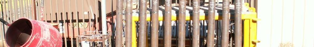
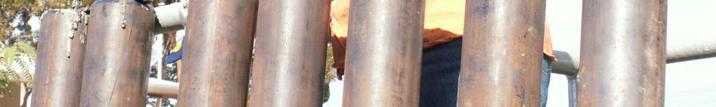
5 Introduction pre 2007 damage

6 Introduction pre 2007 damage

7 Introduction pre 2007 damage


8 Introduction pre 2007 damage
9 Introduction pre 2007 damage
10 Seismic Control History of Demand Splitsets, weld mesh and fibrecrete Failures controlled or influenced by structures Depth of failure 1-2m Different response between walls and backs of development Principally during development cycle Knowledge Felsic unit contacts exposed with development identified as high seismic potential, requires understanding of lithology location standard in-cycle seismic ground support scheme Occasionally occurs along Fitzroy fault during production Seismic clustering sometimes observed in advance of development and appropriate support installed.
11 Mine Requirements Single pass yielding bolt integrated into the ground support scheme, utilising resin and the jumbo to install Develop a standard ground support scheme for high seismic potential ground Detailed list of all 18 requirements in the paper
12 Mine Implementation of a new bolt Identify the problem (2005) single pass reinforcement system for seismic headings select a suitable reinforcement system allowing closure in a controlled manner more then 300mm closure requires rehabilitation Four bolts selected for basic underground installation trial and pull test (2005) Select one bolt to proceed to dynamic testing (2006) Underground installation and then dynamic lab testing (2007) Analysis of results (2007) Underground training and installation (2007) Set the standard seismic ground support scheme

13 Selection characteristic for Garford Solid Yielding bolt 6 key characteristic Yielding mechanism provides controlled displacement designed to be resin installed single pass designed to be installed in 45mm no significant problems in initial installation trials consistent performance during trials no corrosion problems identified
14 Dynamic lab testing of selected bolt Test version one of the bolt Installed in grout in thick wall steel pipe Analysis and make recommendations for improvement Test version two of the bolt Installed in grout in thick wall steel pipe Proceed to underground testing in rough simulated borehole Development of rough simulated borehole Jumbo installs bolt underground, sample recovered and tested in dynamic lab Jumbo installs Garford Yielding bolts in rough simulated bore underground using standard practices for resin bolts Samples recovered Jumbo installed resin bolts tested in the dynamic lab Samples dissected for analysis
15 Dynamic lab testing version 1 Standard WASM test 36kJ kinetic energy of collar mass 2tonnes at 6m/s at impact Consistent performance 125kN 33kJ absorbed Results compared to cone bolts High displacement results means high energy absorption capacity required can the support system cope with the allowed deformation from the reinforcement system Additional rockmass fracturing will occur High deformation system allow higher ejection velocities Decision to develop version 2 increase resistive force, decrease displacement Add end stop mechanism to utilise full capacity of the steel bar
16 Dynamic lab testing comparison Dynamic Force Displacement Curves 220 Force (kn) Cone bolt 32, 40MPa Grout Cone bolt 41, 40MPa Grout Cone bolt 60, 20MPa Grout Cone bolt 61, 20MPa grout 60 Garford Solid yielding bolt Garford Solid yielding bolt Displacement (mm)
17 Dynamic lab testing version 1 Standard WASM test 36kJ kinetic energy of collar mass 2tonnes at 6m/s at impact Consistent performance 125kN 33kJ absorbed Results compared to cone bolts High displacement results means high energy absorption capacity required can the support system cope with the allowed deformation from the reinforcement system Additional rockmass fracturing will occur High deformation system allow higher ejection velocities Decision to develop version 2 increase resistive force, decrease displacement Add end stop mechanism to utilise full capacity of the steel bar


18 Rough simulated borehole


19 Rough simulated borehole


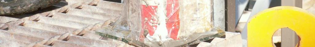
20 Rough simulated borehole

21 Rough simulated borehole


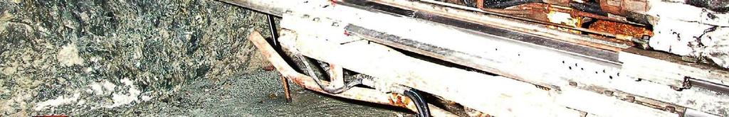
22 Rough simulated borehole
23 Dynamic lab testing version 2 Shorter displacement then V1 145kN 26kJ Resin encapsulation performance slightly different to grout encapsulation possible damage during installation End stop mechanism worked well maximising capacity of the steel Bolt survived remarkably well from single load, undertake multiple loads Systems that survive repeat testing should also have a single high energy test to assess consistency in performance rather then adding results because ground is fractured and loading mechanism changes or ground would not be susceptible to a second event Concept of critical and non-critical loading conditions
24 Dynamic lab testing version 2 Dynamic force displacement response for Improved Solid Yielding Garford Bolts Bolt 89 Bolt 90 Bolt 97 Bolt 98 Bolt 99 Bolt 100 Bolt 97 resin is in the yielding mechanism, higher forces recorded Load (kn) Bolt 89 and 90, installed in 80MPa grout (indicates, idealised performance) Bolt 98 & 99, installed by jumbo in resin Bolt 100 8m/s impact, reduces dynamic frictional resistance Displacement (mm)

25 Dynamic lab testing version 2 Dissection of samples Mixing device very effective Rotate and push through resin best performance Over drill by mm to allow resin back to gather at the end of the hole 260mm of resin below anchor point is sufficient to generate full bolt capacity Velocity Dependence exhibited by lots of materials dynamic friction generally less than static friction 260mm 450mm


26 Version 1 vs Version 2 Version 1 125kN 37kJ Version 2 145kN 26kJ Both bolts loaded to the standard WASM dynamic index test
27 Mine standard calculation Based on energy calculations Kinetic energy of ejection + potential energy change from drive closure Primary Kinetic energy = ½ mv 2 Mass historical depth of failure backs 1m, walls 1.5m a selected bolt pattern, static capacity post event Walls 1.5 * 0.75 Backs 1.5 * 1.5 Velocity Published information 0.5 5m/s Reinforcement system response based on testing Tables of performance in the paper Bulking criteria Ignore contribution from surface support
28 Support System Design Current support system design implemented at KB for high seismic hazard areas
29 Support System Design FLOOR WALL WALL FLOOR BACK Current support system design implemented at KB for high seismic hazard areas
30 Dynamic Support System Response Bolt Displacement Assessment Criteria:
31 Backs bolt spacing empirical basis (1.5mx1.5m) Historic bolt spacing practices adopted as a basis limited dynamic failure observed along the backs. Arched shape shape is inherently stable. In-cycle fibrecrete locks arch shape and key-blocks into place. Surface support combined with arch stability effects Reduce bolt displacement 325mm to 160mm (3m/s velocity; 1m depth of failure). 1.5mx1.5m versus 1.5mx0.75m Saving of 8 bolts per 3m of development. Rockmass deterioration in the backs could reduce the arch effectiveness for an increased stress environment.
32 Walls bolt spacing empirical basis (1.5mx0.75m) Denser spacing practice than historically utilised historically walls most vulnerable to dynamic failure. Walls are not locked into an arched shape walls have the potential to flap (oscillate) in a dynamic situation Rockmass relaxation occurs along the walls easily allowing block movement under dynamic conditions. Wall integrity is integral to maintaining the arch shape maintains the stability of the backs.
33 Bolt Implementation at KB Operators unfamiliar with bolts installed with resin Only 5-10% of development requires seismic standard Total development of 4.5km per annum Logistics of operator training 100mm of over drill easier to install, less then exposed at collar of hole Operator turnover Too many splitset to hold mesh up QAQC mainly by observation Developing a practical installation standard and design Change to fast set resins in conjunction with u/g refrigerated storage worked very well Installation into damaged ground Installing one bolt at a time worked, drilling all holes and then trying to install didn t
34 Planned Support Design Optimization Dynamic testing of the individual surface support components and the combined support system in collaboration with WASM. Establish site specific seismic demand calculations Collection of near field source data Establish potential depth of failure around development Quantify the damaged zone surrounding the development. Verify the empirical design assumptions, the underground performance of the support system, and identify any potential design weaknesses. Investigate self drilling bolts for rehab in very broken ground
35 Conclusion Kanowna Belle has successfully implemented a well tested one-pass dynamically capable support system as part of the development cycle at the mine. 1. Indentify requirements at the mine 2. Indentify a bolt that might suit requirements 3. Basic installation and static tests underground 4. Dynamic test bolt in simulated boreholes 5. Jumbo installed bolt and dynamically test 6. Introduce as standard, training for operators