RESOLUTION HEIGHTS, GULF HARBOUR GEOTECHNICAL COMPLETION REPORT
|
|
|
- Nigel Bailey
- 5 years ago
- Views:
Transcription

1 18 July 2016 RESOLUTION HEIGHTS, GULF HARBOUR GEOTECHNICAL COMPLETION REPORT Top Harbour Limited Ref: AKL2016_0066AF Rev: 0 Building C, 9 Piermark Drive, Rosedale, Auckland
2 Resolution Heights, Gulf Harbour 18 July 2016 Table of Contents 1. INTRODUCTION PROJECT BACKGROUND DESCRIPTION OF EARTHWORKS GEOTECHNICAL QUALITY CONTROL Site Observations Compaction Control EVALUATION OF COMPLETED EARTHWORKS Comprehensive Design of Lots Natural Hazards Land Stability and Erosion Control Retaining Walls and Rock Faced Batters Retaining Wall Drainage Outlets Fill Induced Settlement Subsoil Drains Service Line Trenches Road Subgrades Design of Shallow Foundations Bearing Capacity Foundation Settlements Soil Expansiveness Classification Topsoil Depths CLOSURE... 6 Appendices Appendix A Statement of Professional Opinion as to the Suitability of Land For Building Development Appendix B Drawings Appendix C Laboratory Test Data Appendix D Field Test Data Appendix E Producer Statement CMW Geosciences (NZ) Ltd Ref: AKL2016_0066AF Rev: 0 Geotechnical Completion Report This report is to be read in its entirety together with the appended Statement of Professional Opinion i
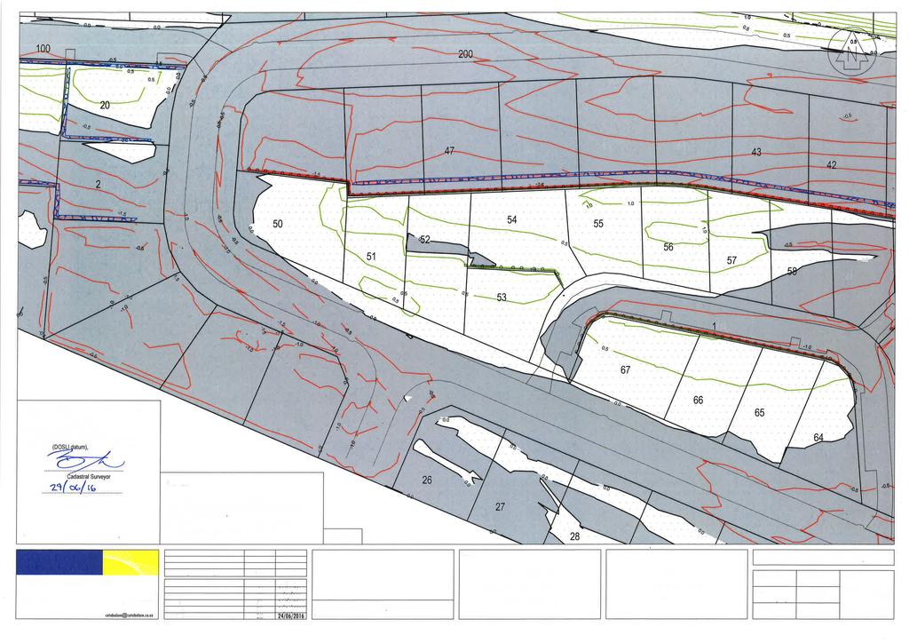
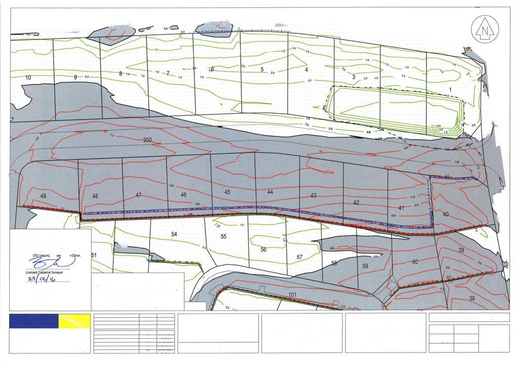
3 Resolution Heights, Gulf Harbour 18 July INTRODUCTION In accordance with our instructions, this Geotechnical Completion Report has been prepared for Top Harbour Limited as part of the documentation to be submitted to Auckland Council following earthworks to form the Resolution Heights Development at Pinecrest Drive, Hobbs Point. Construction of this residential subdivision has been undertaken in accordance with the Auckland Council Resource Consent number R65338 dated 22 October Specific structures constructed during the civil works to create the subdivision include timber pole retaining walls and rock faced batters. This report contains our Suitability Statement, specific comments related to items raised in the Resource Consent, relevant test data and the Cato Bolam Consultants Limited as-built plan set as provided in Appendix B. This report covers the construction period October 2015 to June 2016 and is intended to be used for certification purposes for new lots (listed below) created from Lot 30 DP as follows: 68 new residential lots numbered 1 to 67; 1 new loop road numbered lot 200 and two jointly owned accessways numbered lots 100 and 101. A balance lot (lot 300) has been created but no geotechnical assessments have been made on this lot. As can be seen from the as-built plans, 45 of the lots have been affected by filling as part of these earthworks operations to a maximum depth of approximately 3 metres. These earthworks are in addition to those carried out in 2006/2007 as described in Section 2 below. 2. PROJECT BACKGROUND Earthworks were previously carried out on this site in 2006/2007 and were associated with the forming of the Anchorage immediately to the north. Geotechnical investigations, design, construction monitoring and certification were undertaken by Foundation Engineering and subsequently by Coffey Geotechnics (following their merger) by staff who are now working for CMW Geosciences. In the process a shear key was excavated beneath the length of the Anchorage that in places extended into the toe of the subject site. Fill depths up to 9m were required in the shear key backfilling. In addition, an original gully alignment through the site was filled with engineered fills up to approximately 3m deep. During the construction of the shear key, an area above the key slid into the rear of the excavation. Following toe stabilisation by backfilling of the shear key, the area was undercut to 2m depth and a series of subsoil drains were installed to control pore water pressures before engineered backfill was compacted to form the final level. These works were all certified in the Coffey Geotechnics GCR referenced GEOTOREW11095 dated 9 January A copy of the Harrison Grierson Consultants plan showing cut/fill and subsoil drains are appended to this report. Further geotechnical investigations and design for this development were undertaken by CMW Geosciences NZ Limited as presented in the following reports: AKL2016_0066AA Rev. 2 dated 3 August 2015 AKL2016_0066AC Rev. 0 dated 24 November 2015 CMW Geosciences (NZ) Ltd 1 Ref: AKL2016_0066AF Rev: 0 Geotechnical Completion Report This report is to be read in its entirety together with the appended Statement of Professional Opinion
4 Resolution Heights, Gulf Harbour 18 July DESCRIPTION OF EARTHWORKS Earthworks operations for this site commenced in October 2015 involving the formation of the silt pond and erosion controls across the site. In early November topsoil stripping operations began. Filling operations commenced immediately after stripping of topsoil. Fill materials were derived from on site. By early December drainage works were in progress. This work progressed through the season and was largely completed by mid-april The quality of the backfill in drainage trenches was tested to confirm that it met the specification requirements. In late December 2015 construction of retaining walls commenced. Some of the retaining walls encountered soils having lower than expected shear strengths and the design embedment depth was increased to account for these conditions. By January 2016, bulk earthworks were largely complete. Trimming of road subgrades, lot platforms and construction of rock batter faces was being undertaken. The mucking out of the temporary silt pond on lots 1-3 and subsequent backfilling commenced in late March. By early-may the majority of lots were either top-soiled or mulched. Earthworks and civil works were mostly complete. The main items of plant used by the contractor, Hibiscus Contractors Limited and their earthworks sub-contractor Glamuzina Contractors, included: Various excavators between 5 and 20T 1x 825 pad foot compactor 2x bulldozers and scoops 1x Dump truck 1x Vibrating pad foot compactor 4. GEOTECHNICAL QUALITY CONTROL 4.1. Site Observations During the earthworks site visits were typically undertaken several times each week to assess compliance with NZS 4431 and specific design recommendations and specifications. Site visits were carried out to observe and confirm compliance relating to: Adequate topsoil stripping; Fill areas prior to the placement of fill materials to ascertain that any soft inorganic subsoils had been removed; Backfilling of sewer and stormwater trenches; Rock batter face formation; and, Construction of cantilever pole retaining walls including ground conditions, pile size, spacing and depth Compaction Control Compaction of engineered earth fills was controlled by undrained shear strength measured by hand held shear vane calibrated using the NZGS 2001 method and by air voids as defined by NZS4402. CMW Geosciences (NZ) Ltd 2 Ref: AKL2016_0066AF Rev: 0 Geotechnical Completion Report This report is to be read in its entirety together with the appended Statement of Professional Opinion
5 Resolution Heights, Gulf Harbour 18 July 2016 General Fills The criteria for undrained shear strength were a minimum single value of 110 kpa and minimum average of any 10 consecutive tests of 140 kpa. The criteria for air voids were a maximum single value of 12% and maximum average of any 10 consecutive tests of 10%. Vane shear strength, water content and in situ density tests were carried out on all areas of the engineered filling to at least the frequency recommended by NZS Our testing confirmed compliance with the specification, for the finished works. 5. EVALUATION OF COMPLETED EARTHWORKS 5.1. Comprehensive Design of Lots Lots 36 to 67 inclusive have been formed in alignment with a Comprehensive Development Plan (CDP) that has been agreed with Council. Specific house typologies have been designed for these lots to provide the desired visual effects in the built form. As part of the CDP, split level houses have been designed for lots 51, 52, 56, 57, 58 and 59. Accordingly, these lots have been formed with low, steep batters through their central portions. The future buildings planned for these lots will address batter stability via retaining walls integrated in the buildings. For these walls the following soil parameters are suitable for design: Unit weight, γ = 17.5kN/m3 Effective stress friction angle, Ø = 27⁰ Undrained shear strength, Su = 60 kpa 5.2. Natural Hazards The appended as-built drawings depict the extents of a series of zones that contain limitations intended to ensure that future building and/ or earthworks on the lots is undertaken in a manner that does not lead to buildings being subject to any of the natural hazards described in section 106 of the Resource Management Act, i.e. erosion, falling debris, subsidence, slippage, and inundation. Consideration of the inundation hazard was outside the scope of CMW s brief and has been assessed by others. The applied zones include: Specific Design Zones (retaining) - intended to protect the retaining walls and rock faced batters from overloading at the crest or undermining at the toe that could lead to instability; and, Specific Design Zones (banks) intended to protect building development from long term creep effects on or adjacent to steep slopes and to protect the slopes from inappropriate loading or undermining. Full descriptions of the restrictions associated with each of these zones are presented in the Suitability Statement (Appendix A). Additional information is also provided in some of the following sections Land Stability and Erosion Control The subdivision scheme layout includes a series of retaining walls, rock faced batters and un-faced batter slopes to form level terraces for building platforms. The batters include portions of the residential lots with maximum gradients of 1(v) in 2.5(h) as depicted on the as-built drawings. In addition to these batter slopes, temporary batters have been constructed within lots 51, 52, and 56 to 59 inclusive as explained in Section 5.1. CMW Geosciences (NZ) Ltd 3 Ref: AKL2016_0066AF Rev: 0 Geotechnical Completion Report This report is to be read in its entirety together with the appended Statement of Professional Opinion
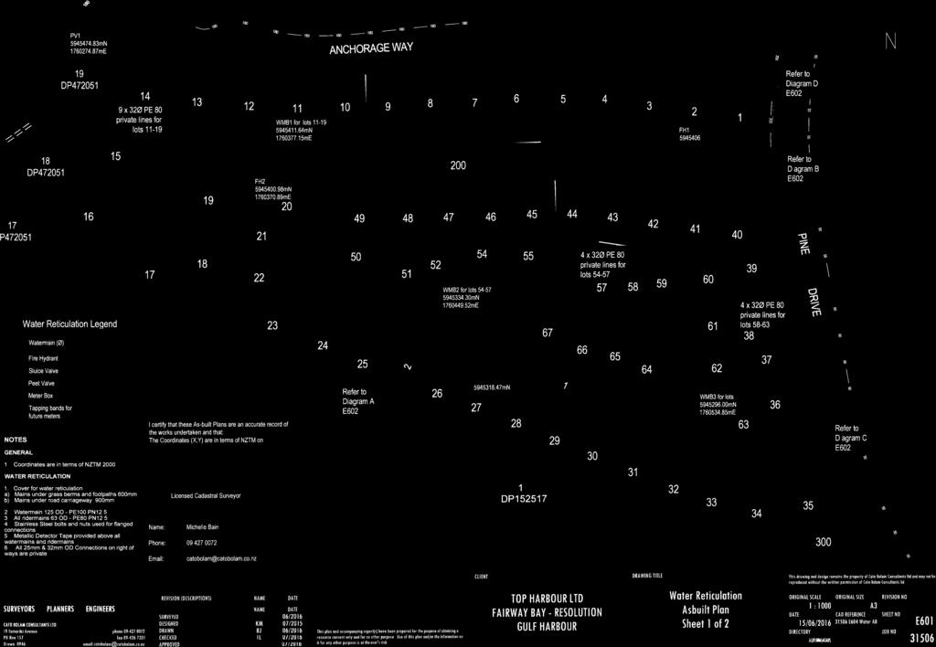
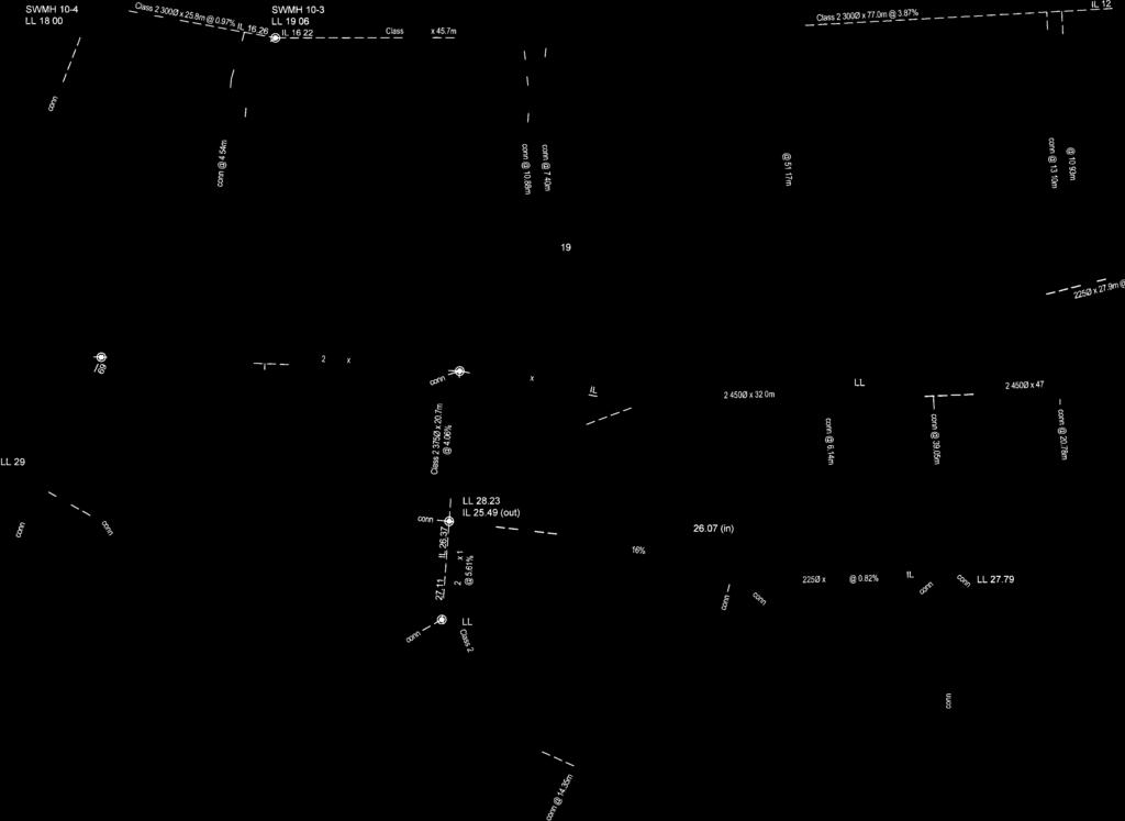
6 Resolution Heights, Gulf Harbour 18 July 2016 Apart from the temporary batters mentioned above, stability conditions for finished ground profiles have been assessed under a range of groundwater conditions which satisfy ultimate limit state design criteria. The soil parameters for the analyses were selected from extensive investigation undertaken at the site and from experience in this terrain. We consider that the stability results are satisfactory for these building platform areas and we are therefore satisfied that these areas are not subject to the natural stability hazards described in Section 106 of the Resource Management Act and Section 71(3) of the Building Act. In addition, all landowners and landscape designers should note that surface stability can be compromised by indiscriminate disposal of stormwater onto the ground surface and/ or by removal of vegetation. Designers must ensure that all runoff from solid surfaces is directed into the stormwater system and it is also important that care is paid to the disposal of stormwater during construction so that concentrated discharges (e.g. from unconnected spouting) are not directed towards steep ground Retaining Walls and Rock Faced Batters Cantilever pole retaining walls and rock facings to batters have been constructed in the locations shown on the appended Final Contours As-built Plans. These walls and batter facings reach a maximum height of approximately 2 metres and were designed by CMW Geosciences NZ Limited and the construction was observed by this consultancy. A copy of the Producer Statement - Construction Review for the retaining walls is provided in Appendix E. Descriptions of the building and earthworks restrictions within the vicinity of these walls and batter facings (Specific Design Zones retaining) are contained in the Suitability Statement in Appendix A. Lots containing these zones include 14 to 16 inclusive, 18 to 21 inclusive and 36 to 67 inclusive Retaining Wall Drainage Outlets We understand that retaining wall drainage has not yet been connected into the storm water network. It is important on each affected lot that these outlets are connected into the public storm water system during the construction of the dwelling. This may be most economically achieved by connection with the roof downpipe drainage systems Fill Induced Settlement On the basis of the relatively minor magnitude of fill depths on this site, together with the elapsed time since it was placed, we consider that remaining post-construction settlements will be within code limits Subsoil Drains Previous earthworks on this site carried out in 2006/2007 included the construction of a shear key and associated sub soil drainage. These run beneath Lots 1 to 15 inclusive, 19 to 21 inclusive, 49 and 50. Locations are depicted on the appended Harrison Grierson Consultants as-built drawings. These drains require no maintenance and are expected to be well below normal foundation excavations. Nevertheless, it is important that their function is protected if they are excavated during piling works. Further detail is provided in the appended Suitability Statement Service Line Trenches As part of the civil works, sanitary sewer and stormwater services were trenched throughout the development as shown on the appended Stormwater and Sanitary Sewer As-built Plans. As is normal on all subdivisions, building developments involving foundations within a 45 degree zone of influence from pipe inverts will require engineering input. The Auckland Council drawing referenced CMW Geosciences (NZ) Ltd 4 Ref: AKL2016_0066AF Rev: 0 Geotechnical Completion Report This report is to be read in its entirety together with the appended Statement of Professional Opinion
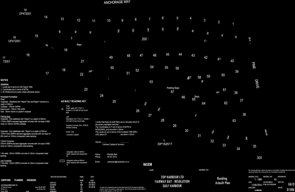
7 Resolution Heights, Gulf Harbour 18 July 2016 SW22 provided in Appendix B extracted from Chapter 4 of the Auckland Council Code of Practice for Land development and Subdivision depicts their requirements for stormwater pipes. Details for water and wastewater pipes are available in the Watercare COP1 - General Requirements and Procedures. The majority of lots are known to have service trenches within their boundaries as shown on the appended stormwater and wastewater as-built plans. The resulting restrictions are presented in the Suitability Statement below Road Subgrades Penetration resistance testing was carried out on the road subgrades during construction and the results of this testing were forwarded to Cato Bolam Consultants Limited for pavement remedial design Design of Shallow Foundations Bearing Capacity Once bulk earthworks and top-soiling or mulching of the building platforms had been completed, our staff drilled hand auger boreholes on platforms in natural ground and shallow fill to determine representative finished ground conditions and hence evaluate likely foundation options for future building development. Our assessments of bearing capacity for the design of shallow foundations on each building platform are contained in the appended Suitability Statement. At current subgrade levels lots 1 to 67 inclusive have been assessed as having a geotechnical ultimate bearing capacity of 300kPa within the influence of conventional shallow residential building foundation loads, although if any ponding has occurred during heavy rain on portions of any of the lots, there may be softening of the surface layer. If higher geotechnical ultimate bearing capacities are required, further specific site investigation and design of foundations should be carried out prior to Building Consent application. No assessment has been made on lot Foundation Settlements At the bearing pressures specified above and subject to the design requirements for soil expansiveness provided below, differential settlement of shallow foundations for buildings designed in accordance with NZS 3604 (including the 600mm subfloor fill depth limit) should be within code limits Soil Expansiveness Classification Six sets of soil tests were carried out on samples taken from likely foundation level on lots within the development. Testing was carried out in accordance with NZS 4402, "Methods of Testing Soils for Civil Engineering Purposes" test 2.2 and 2.6 and the results were used in conjunction with visual-tactile assessment of the site soils to determine expansive site Classes as defined in AS 2870, "Residential Slabs and Footings Construction". All test results are appended. On this basis we have assessed the AS 2870 Site Class for all lots this stage of the development to be H1 (high). Details of foundation options for this Class are contained in the appended Suitability Statement. In recent years in Auckland, there have been examples of concrete floors and/ or foundations that have been poured on dry, desiccated subgrades in summer months on expansive soils and have undergone heaving and cracking once the soil moisture contents have returned to higher levels. Foundation contractors need to be made aware of this issue and the need to maintain appropriate CMW Geosciences (NZ) Ltd 5 Ref: AKL2016_0066AF Rev: 0 Geotechnical Completion Report This report is to be read in its entirety together with the appended Statement of Professional Opinion
8 Resolution Heights, Gulf Harbour 18 July 2016 moisture contents in the footings and building platform subgrade between the time of excavation and the pouring of concrete. Remedial actions that may be appropriate include platform protection with a hard fill layer, pouring of a blinding layer of concrete in footing bases and soaking of the building platform with sprinklers for an extended period. Home owners need to be aware that the planting of high water demand plants where their roots may extend close to footings can also cause settlement damage Topsoil Depths Topsoil depths have been checked by the drilling of a borehole in the approximate centre of the building platform on each lot. The results are considered indicative for each lot, but may be subject to variations. Topsoil depths are between 50 and 300mm on these stages of the development. Lots 50 to 67 inclusive have been covered in mulch rather than topsoil. Site specific findings are contained in the appended Suitability Statement Summary (Appendix A). However, it is possible that further levelling works have been undertaken since our investigations and accordingly, we strongly recommend that lot purchasers complete their own checks of topsoil depths. 6. CLOSURE The appended Statement of Professional Opinion is provided to the Auckland Council and Top Harbour Limited for their purposes alone on the express condition that it will not be relied upon by any other person. It is important that prospective purchasers satisfy themselves as to any specific conditions pertaining to their particular land interest. Although regular site visits have been undertaken for observation, for providing guidance and instruction and for testing purposes, the geotechnical services scope did not include full time site presence. To this end, our appended Suitability Statement also relies on the Contractors work practices and assumes that when we have not been present to observe the work, it has been completed to high standards and in accordance with the drawings, instructions and consent conditions provided to them. Similarly it assumes that all as-built information and other details provided to the Client and/or CMW by other members of the project team are accurate and correct in all respects. For and on behalf of CMW Geosciences (NZ) Limited Prepared by: Reviewed and Approved by: Jack Mynett - Johnson Engineering Geologist Richard Knowles Principal Geotechnical Engineer, CPEng CMW Geosciences (NZ) Ltd 6 Ref: AKL2016_0066AF Rev: 0 Geotechnical Completion Report This report is to be read in its entirety together with the appended Statement of Professional Opinion
9 Appendix A Statement of Professional Opinion as to the Suitability of Land for Building Development
10 Resolution Heights, Gulf Harbour 18 July 2016 STATEMENT OF PROFESSIONAL OPINION AS TO THE SUITABILITY OF LAND FOR BUILDING DEVELOPMENT I, R.J. Knowles, of CMW Geosciences (NZ) Limited, Auckland, hereby confirm that: 1. I am a Chartered Professional Engineer experienced in the field of geotechnical engineering as defined in section of NZS 4404 and was retained by the Developer as the Geotechnical Engineer on the Resolution Heights Development. 2. The extent of preliminary investigations carried out to date are described in the CMW Geosciences NZ Limited Geotechnical Investigation Report referenced AKL2016_0066AA Rev. 2, dated 3 August The conclusions and recommendations of those documents have been re-evaluated in the preparation of this report. The results of all tests carried out are also appended. 3. In my professional opinion, not to be construed as a guarantee, I consider that: (a) The earth fills shown on the appended Cato Bolam Consultants Limited Cut and Fill Contours As-built Plan have been placed in compliance with NZS 4431, the Legacy Rodney District Council Plans and related documents. (b) The completed earthworks give due regard to land slope and foundation stability considerations on the building platform areas, but as shown on the appended building restriction zones plans, areas on some lots have gradients steeper than 1(v) in 4 (h) (and generally up to 1(v) in 2.5(h)) or are adjacent to land having such gradients. Accordingly, Specific Design Zone (bank) areas have been applied on Lots 1 to 16 inclusive, 18, 22 to 25 inclusive, 31 to 38 inclusive, 40, 48 to 52 inclusive, 56 to 59 inclusive and 61 to 63 inclusive. No building construction and no earthworks (i.e. cut or fills of any depth) should take place within the designated Specific Design Zone (Slope) areas unless endorsed by a Chartered Professional Engineer experienced in geomechanics and familiar with the contents of this report. The endorsement will need to consider the implications of the proposals on both global stability conditions and soil creep on the building buildings, the interaction with service pipes and associated trench backfills, control of surface water, construction sequencing, timing and temporary support requirements construction of all earthworks, foundations and retaining walls and if necessary, comment on what aspects require engineering inspections and certification. No assessment has been made for balance lot 300. This limitation also applies to long term landscaping works, including any proposed minor cuts either on or near batter toes to be retained by new landscaping walls that might not normally require engineering, and to landscaping fills on or immediately above the batter slopes. (c) Specific Design Zone (Retaining) areas have been applied on Lots 14, 15, 19 to 21 inclusive and 36 to 67 inclusive for the protection of the function of the retaining walls and rock faced batters. No building construction and no earthworks (i.e. cut or fills of any depth) should take place within the designated Specific Design Zone (Retaining) areas unless endorsed by a Chartered Professional Engineer experienced in geomechanics and familiar with the contents of this report. The endorsement will need to consider the stability implications of the earthworks and building proposals on the retaining walls. (d) A geotechnical ultimate bearing capacity of 300 kpa may be assumed for shallow foundation design on the building platforms of Lots 1 to 67 inclusive. CMW Geosciences (NZ) Ltd Ref: AKL2016_0066AF Rev: 0 Appendix A Geotechnical Completion Report This Statement of Professional Opinion is to be read together with the full Geotechnical Completion Report ii
11 Resolution Heights, Gulf Harbour 18 July 2016 If for any reason higher geotechnical bearing capacities are required, further specific site investigation and design of foundations should be carried out prior to Building Consent application. No assessment has been made for the balance lot 300. (e) The expansive site Class for all lots has been assessed as AS2870 Class H1 (High). We recommend that building designers note on the Building Consent drawings the need to maintain appropriate moisture levels across building subgrades and in footing excavations (as described in Section of the Geotechnical Completion Report) for reference by foundation contractors. (f) The backfilling and compaction of the storm water and sanitary sewer trenches on this subdivision has been carried out to appropriate standards having regard for the prevailing ground conditions and associated compaction induced pipe loadings. However, no building development should take place within the 45 degree zone of influence of drain inverts unless endorsed by specific design and by construction inspections undertaken by a Chartered Professional Engineer experienced in geomechanics to ensure that lateral stability and differential settlement issues are addressed and that building loads are transferred beyond the influence of the pipe and trench backfill. A copy of drawing SW22 extracted from Chapter 4 of the Auckland Council Code of Practice for Land development and Subdivision this document is provided in Appendix B for clarification. Details for water and wastewater pipes are available in the Watercare COP1 - General Requirements and Procedures. (g) Subject to the geotechnical limitations, restrictions and recommendations contained in clauses, 3(b), 3(c), 3(d), 3(e) and 3(f) above: (i) The filled and natural ground is generally suitable for residential buildings constructed in accordance with NZS 3604 and the requirements of AS2870 for the appropriate expansive soil class. (ii) Where shallow foundations are appropriate, design may be carried out in accordance with AS 2870 (Class H1) or alternately, a specific foundation and structural design may be undertaken by a Chartered Professional Engineer. 4. Road subgrades have been formed with appropriate regard for slope stability and settlement risks. The following table summarises the conditions on each of each residential lots. For and on behalf of CMW Geosciences (NZ) Limited Richard Knowles Principal Geotechnical Engineer, CPEng CMW Geosciences (NZ) Ltd Ref: AKL2016_0066AF Rev: 0 Appendix A Geotechnical Completion Report This Statement of Professional Opinion is to be read together with the full Geotechnical Completion Report iii
12 Resolution Heights, Gulf Harbour 18 July 2016 GCR Summary Table Condition Specific Design Zone (banks) Specific Design Zone (retaining) Geotechnical Ultimate Bearing Capacity (kpa) AS2870 Expansive Class Anticipated Service Line Restrictions Indicative Topsoil Depth (mm) GCR SOPO Clause Lot number 3(b) 3(c) 3(d) 3(e) 3(f) H H H H H H H H H H H H H H H H H H H1 150 CMW Geosciences (NZ) Ltd Ref: AKL2016_0066AF Rev: 0 Appendix A Geotechnical Completion Report This Statement of Professional Opinion is to be read together with the full Geotechnical Completion Report iv
13 Resolution Heights, Gulf Harbour 18 July 2016 Condition Specific Design Zone (banks) Specific Design Zone (retaining) Geotechnical Ultimate Bearing Capacity (kpa) AS2870 Expansive Class Anticipated Service Line Restrictions Indicative Topsoil Depth (mm) GCR SOPO Clause Lot number 3(b) 3(c) 3(d) 3(e) 3(f) H H H H H H H H H H H H H H H H H H H H H1 150 CMW Geosciences (NZ) Ltd Ref: AKL2016_0066AF Rev: 0 Appendix A Geotechnical Completion Report This Statement of Professional Opinion is to be read together with the full Geotechnical Completion Report v
14 Resolution Heights, Gulf Harbour 18 July 2016 Condition Specific Design Zone (banks) Specific Design Zone (retaining) Geotechnical Ultimate Bearing Capacity (kpa) AS2870 Expansive Class Anticipated Service Line Restrictions Indicative Topsoil Depth (mm) GCR SOPO Clause Lot number 3(b) 3(c) 3(d) 3(e) 3(f) H H H H H H H H H H H H H H H H H H H H H1 0 CMW Geosciences (NZ) Ltd Ref: AKL2016_0066AF Rev: 0 Appendix A Geotechnical Completion Report This Statement of Professional Opinion is to be read together with the full Geotechnical Completion Report vi
15 Resolution Heights, Gulf Harbour 18 July 2016 Condition Specific Design Zone (banks) Specific Design Zone (retaining) Geotechnical Ultimate Bearing Capacity (kpa) AS2870 Expansive Class Anticipated Service Line Restrictions Indicative Topsoil Depth (mm) GCR SOPO Clause Lot number 3(b) 3(c) 3(d) 3(e) 3(f) H H H H H H1 0 CMW Geosciences (NZ) Ltd Ref: AKL2016_0066AF Rev: 0 Appendix A Geotechnical Completion Report This Statement of Professional Opinion is to be read together with the full Geotechnical Completion Report vii
16 Appendix B Drawings Title Reference No. Date Revision Cato Bolam As-Built Plans E /07/2016 Harrison Grierson Consultants Ltd As-Built Set Harrison Grierson Consultants Ltd SW As- Built Auckland Council Stormwater Pipe and Manhole Clearance Requirements Lot / RD1-400 SWCoP-SW22 10/2007 A A 01/11/2015 2
17

18


19


20


21


22


23

24

25

26

27

28


29
30
31

32

33

34
35

36


37

38
39
40
41
42
43
44
45
46
47
48
49
50 Appendix C Laboratory Test Data
51 Revision: 1 Report No: Page: of 1 DETERMINATION OF THE LIQUID LIMIT & LINEAR SHRINKAGE TEST METHOD NZS 4402 : 1986 TEST 2.2 & 2.6 Job: Date of order: Sample method: Sample By: Resolution Heights CMW Geosciences Sample origin: Sample Description: Date: Test Details : Test performed on : History : whole soil Natural Liquid Linear Natural Sample No. Location Depth Limit Shrinkage Water Content (m) (%) E174A Lot E175A Lot E176A Lot E177A Lot Comments : Tested By: EC Date : Calculated By : EC Date : Checked By : EC Date :
52 Revision: 1 Report No: Page: of 1 DETERMINATION OF THE LIQUID LIMIT & LINEAR SHRINKAGE TEST METHOD NZS 4402 : 1986 TEST 2.2 & 2.6 Job: Date of order: Sample method: Sample By: Resolution Heights Handauger MP Sample origin: Sample Description: Date: Test Details : Test performed on : History : Whole Soil Natural Liquid Linear Natural Sample No. Location Depth Limit Shrinkage Water Content (m) (%) E211A Lot m - 0.8m E212A Lot m - 0.9m Comments : Tested By: EC Date : Calculated By : EC Date : Checked By : EC Date :
53 Appendix D Field Test Data
54

55
56
57
58
59
60
61
62
63 Appendix E Producer Statements
64 29 June 2016 Ref: AKL AG Rev.0 Mr M Webb-Speight Top Harbour Limited C/o CMLP PO Box Auckland 1143 Dear Sir RE: CERTIFICATION FOR THE CONSTRUCTION OF TIMBER PILE RETAINING WALLS AT PINECREST DRIVE, GULF HARBOUR - R65338 CMW Geosciences (NZ) Limited (CMW) have visited the site at Pinecrest Drive, Gulf Harbour, legally described as Lot 30 DP on numerous occasions from December 2015 to February 2016 to observe the site works for the construction of timber pile retaining walls. Our work has included review of the following documents and drawings: Conditions of Auckland Council Consent referenced R65338, issued 22 October 2015; Consented construction drawings, prepared by CMW Geosciences (NZ) Limited, referenced AKL2016_0066AC Rev. 0, dated 24 November 2015; Geotechnical report for Pinecrest Drive, Gulf Harbour prepared by CMW Geosciences (NZ) Limited, referenced AKL2016_0066AA Rev. 2, dated 3 August The site works observed and/or tested by CMW staff incorporated: Assessment of soil strengths in the exposed pile-hole excavations. Construction observations for timber pile retaining walls including: pile-hole depths, diameters and spacings; pile small end diameters and treatment levels; lagging thickness and treatment levels and drainage placement. On the basis of our observations and testing, we consider that the works have been undertaken in accordance with the approved Consent and related approved documentation described above and are in accordance with the requirements and/or recommendations of the geotechnical report. For and on behalf of CMW Geosciences NZ Ltd Richard Knowles Principal Geotechnical Engineer, CPEng Attachments: Producer Statement - Construction Review Building C, 9 Piermark Drive, Rosedale, Auckland
65