HOW TO DESIGN CONCRETE STRUCTURES Columns
|
|
|
- Jonah Goodwin
- 5 years ago
- Views:
Transcription

1 HOW TO DESIGN CONCRETE STRUCTURES Columns

2 Instructions for the Members of BIBM, CEMBUREAU, EFCA and ERMCO: It is the responsibility of the Members (national associations) of BIBM, CEMBUREAU, EFCA and ERMCO to translate and/or adapt this publication within their national framework, to publish it under their own name and to disseminate it to their contacts at national level. Copyright: Name of National Member Acknowledgements to the European Concrete Platform EMBARGO: 31 March 2007 The Members of BIBM, CEMBUREAU EFCA and ERMCO are not allowed to publish this brochure before 31 March Copyright: European Concrete Platform (when legal body is established), March All rights reserved. No part of this publication may be reproduced, stored in a retrieval system or transmitted in any form or by any means, electronic, mechanical, photocopying, recording or otherwise, without the prior written permission of the European Concrete Platform: BIBM (International Bureau for Precast Concrete); CEMBUREAU, The European Cement Association; EFCA (European Federation of Concrete Admixtures Associations); ERMCO (European Ready Mixed Concrete Organisation). Published by the European Concrete Platform Editor: Jean-Pierre Jacobs 8 rue Volta 1050 Brussels Layout & Printing by The European Concrete Platform All information in this document is deemed to be accurate by the European Concrete Platform at the time of going into press. It is given in good faith. Information on European Concrete Platform document does not create any liability for BIBM, CEMBUREAU, EFCA and ERMCO. While the goal is to keep this information timely and accurate, the European Concrete Platform cannot guarantee either. If errors are brought to its attention, they will be corrected. The opinions reflected in this document are those of the authors and BIBM, CEMBUREAU, EFCA and ERMCO cannot be held liable for any view expressed therein. All advice or information from the European Concrete Platform is intended for those who will evaluate the significance and limitations of its contents and take responsibility for its use and application. No liability (including for negligence) for any loss resulting from such advice or information is accepted. Readers should note that all European Concrete Platform publications are subject to revision from time to time and therefore ensure that they are in possession of the latest version.
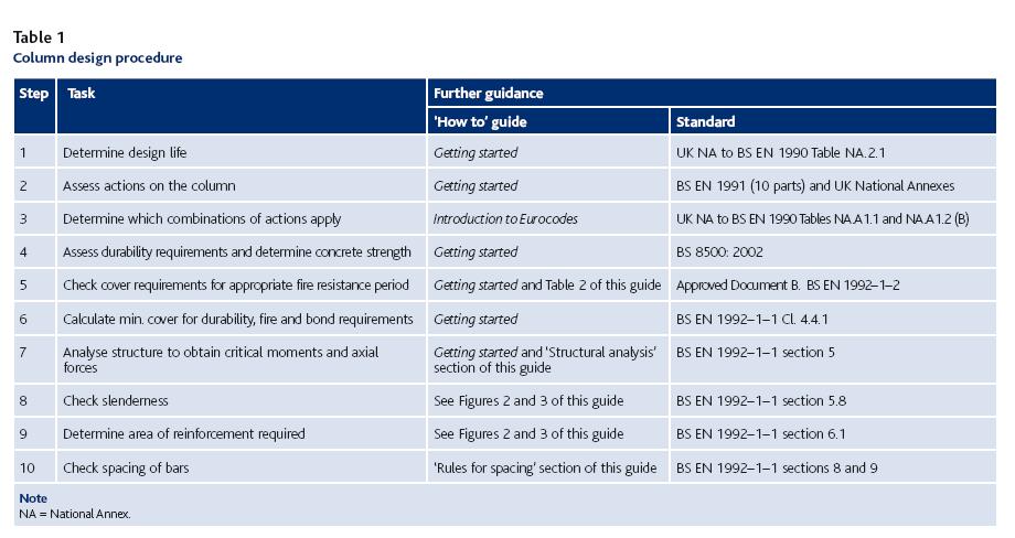
3 How to design concrete structures using Eurocode 2 5. Columns Introduction This should be redrafted as appropriate in each country Designing to Eurocode 2 This guide is intended to assist engineers with the design of columns and walls to Eurocode 2 1. It sets out a design procedure to follow and gives useful commentary on the provisions within the Eurocode. Eurocode 2 does not contain the derived formulae; this is because it has been European practice to give principles and general application rules in the codes and for detailed application rules to be presented in other sources such as textbooks or guidance documents. The first guide in this series, How to design concrete structures using Eurocode 2: Introduction 2, provides an overview of Eurocodes, including terminology. Where NDPs occur in the text in this publication, recommended values in EN 1992 are used and highlighted in yellow. The UK values have been used for NDPs embedded in figures and charts and the relevant NDPs are scheduled separately to assist other users in adapting the figures and charts. (Derivations can be found at A full list of symbols related to column design is given at the end of this guide. Design procedure A procedure for carrying out the detailed design of braced columns (i.e. columns that do not contribute to resistance of horizontal actions) is shown in Table 1. This assumes that the column dimensions have previously been determined during conceptual design or by using quick design methods. Column sizes should not be significantly different from those obtained using current practice. Steps 1 to 4 of Table 1 are covered by earlier guides in this series and the next step is therefore to consider fire resistance. Fire resistance Eurocode 2, Part 1 2: Structural fire design 3, gives a choice of advanced, simplified or tabular methods for determining fire resistance of columns. Using tables is the fastest method for determining the minimum dimensions and cover for columns. There are, however, some restrictions and if these apply further guidance can be obtained from specialist literature. The simplified method may give more economic columns, especially for small columns and/or high fire resistance periods. Rather than giving a minimum cover, the tabular method is based on nominal axis distance, a (see Figure 1). This is the distance from the centre of the main reinforcing bar to the surface of the member.

4

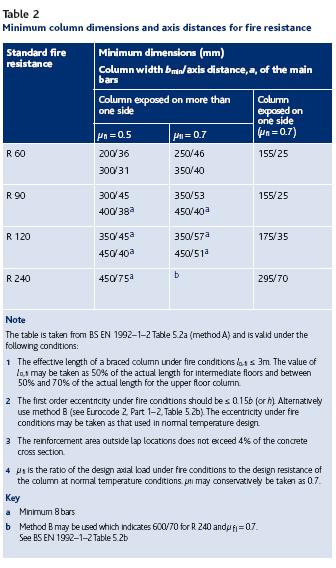
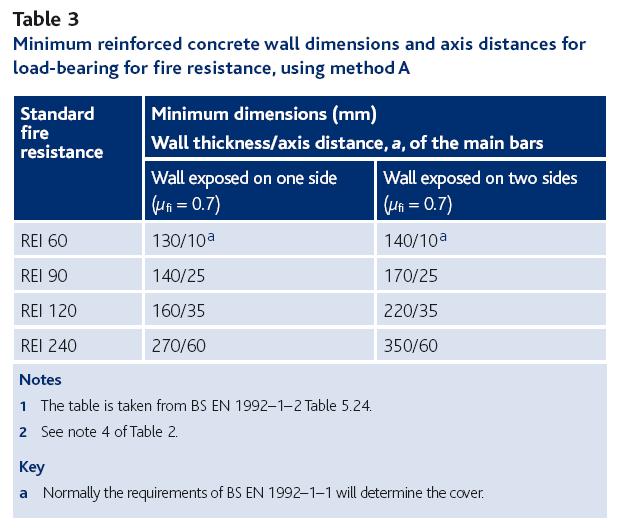
5 It is a nominal (not minimum) dimension, and the designer should ensure that: a c nom + φ link + φ bar /2. For columns there are two tables given in Eurocode 2 Part 1 2 that present methods A and B. Both are equally applicable, although method A has smaller limits on eccentricity than method B. Method A is slightly simpler and is presented in Table 2; limits of applicability are given in the notes. Similar data for load-bearing walls is given in Table 3. For columns supporting the uppermost storey, the eccentricity will often exceed the limits for both methods A and B. In this situation Annex C of Eurocode 2, Part 1 2 may be used. Alternatively, consideration can be given to treating the column as a beam for determining the design fire resistance. Column design A flow chart for the design of braced columns is shown in Figure 2. For slender columns, Figure 3 will also be required. Structural analysis The type of analysis should be appropriate to the problem being considered. The following may be used: linear elastic analysis, linear elastic analysis with limited redistribution, plastic analysis and non-linear analysis. Linear elastic analysis may be carried out assuming cross sections are uncracked (i.e. concrete section properties), using linear stress-strain relationships and assuming mean values of long-term elastic modulus. For the design of columns the elastic moments from the frame action should be used without any redistribution. For slender columns a non-linear analysis may be carried out to determine the second order moments; alternatively use the moment magnification method (Cl ) or nominal curvature method (Cl 5.8.8) as illustrated in Figure 3. Design moments The design bending moment is illustrated in Figure 4 and defined as: M Ed = max {M 02, M 0e + M 2, M M 2 } where: M 01 = min { M top, M bottom } + e i N Ed M 02 = max { M top, M bottom } + e i N Ed e i = max {l o /400, h/30, 20} (units to be consistent with that used for moments). M top, M bottom = Moments at the top and bottom of the column M 0e = 0.6 M M M 02 M 2 = N Ed e 2 where N Ed is the design axial load and e 2 is deflection due to second order effects M 01 and M 02 should be positive if they give tension on the same side. A non-slender column can be designed ignoring second order effects and therefore the ultimate design moment, M Ed = M 02. The calculation of the eccentricity, e 2, is not simple and is likely to require some iteration to determine the deflection at approximately mid-height, e 2. Guidance is given in Figure 3.
6 Effective length Figure 5 gives guidance on the effective length of the column. However, for most real structures Figures 5f and 5g only are applicable and Eurocode 2 provides two expressions to calculate the effective length for these situations. Expression (5.15) is for braced members and Expression (5.16) is for unbraced members. In both expressions, the relative flexibilities at either end, k 1 and k 2, should be calculated. The expression for k given in the Eurocode involves calculating the rotational stiffness of the restraining members making allowance for possible cracking. Once k 1 and k 2 have been calculated, the effective length factor, F, can be established from Table 4 for braced columns. The effective length is then l o = Fl. For a 400 mm square internal column supporting a 250 mm thick flat slab on a 7.5 m grid, the value of k could be 0.11, and therefore l o = 0.59l. In the edge condition k is effectively doubled and lo = 0.67l. If the internal column had a notionally pinned support at its base then l o = 0.77l. In the long term, Expressions (5.15) and (5.16) in the code will be beneficial as they are particularly suitable for incorporation into design software.
 is less than the slenderness limit (λ lim ), then second order effects may be ignored.")
7 Slenderness Eurocode 2 states that second order effects may be ignored if they are less than 10% of the first order effects. As an alternative, if the slenderness (λ) is less than the slenderness limit (λ lim ), then second order effects may be ignored. Slenderness, λ = l o /i where i = radius of gyration and slenderness limit. where A = 1/(1+0.2 ϕ ef ) (if ϕ ef is not known, A = 0.7 may be used) B = (if ω, reinforcement ratio, is not known, B = 1.1 may be used) C = 1.7 r m (if r m is not known, C = 0.7 may be used see below) n = N Ed / (A c f cd ) r m = M 01 /M 02 M 01, M 02 are the first order end moments, M 02 M 01 If the end moments M 01 and M 02 give tension on the same side, r m should be taken positive. Of the three factors A, B and C, C will have the largest impact on λ lim and is the simplest to calculate. An initial assessment of λ lim can therefore be made using the default values for A and B, but including a calculation for C (see Figure 6). Care should be taken in determining C because the sign of the moments makes a significant difference. For unbraced members C should always be taken as 0.7. Column design resistance For practical purposes the rectangular stress block used for the design of beams (see How to design concrete structures using Eurocode 2: Beams 4 ) may also be used for the design of columns (see Figure 7). However, the maximum compressive strain for concrete classes up to and including C50/60, when the whole section is in pure compression, is (see Figure 8a). When the neutral axis falls outside the section (Figure 8b), the maximum allowable strain is assumed to lie between and , and may be obtained by drawing a line from the point of zero strain through the hinge point of strain at mid-depth of the section. When the neutral axis lies within the section depth then the maximum compressive strain is (see Figure 8c).
8 The general relationship is shown in Figure 8d. For concrete classes above C50/60 the principles are the same but the maximum strain values vary. Two expressions can be derived for the area of steel required, (based on a rectangular stress block, see Figure 8) one for the axial loads and the other for the moments: A sn /2 = (N Ed f cd b d c ) / [(σ sc σ st )γ c ] where: A sn /2 = Area of reinforcement required to resist axial load N Ed = Axial load f cd = Design value of concrete compressive strength σ sc (σ st ) = Stress in compression (and tension) reinforcement b = Breadth of section γ c = Partial factor for concrete (1.5) d c = Effective depth of concrete in compression = λx h λ = 0.8 for C50/60 x = Depth to neutral axis h = Height of section A sm /2 = [M f cd b d c (h/2 d c /2)] / [(h/2 d 2 ) (σ sc +σ st )γ c ] where: A sm /2 = Total area of reinforcement required to resist moment Realistically, these can only be solved iteratively and therefore either computer software or column design charts (see Figure 9) may be used. A full range of design charts is available from the website Creep Depending on the assumptions used in the design, it may be necessary to determine the effective creep ratio φ ef (ref. Cl & 5.8.4). A nomogram is provided in the Eurocode (Figure 3.1) for which the cement strength class is required; however, at the design stage it often not certain which class applies. Generally, Class R should be assumed. Where the ground granulated blastfurnace slag (ggbs) exceeds 35% of the cement combination or where pulverized fuel ash (pfa) exceeds 20% of the cement combination, Class N may be assumed. Where ggbs exceeds 65% or where pfa exceeds 35%, Class S may be assumed. Biaxial bending The effects of biaxial bending may be checked using Expression (5.39), which was first developed by Breslaer. where: M edz,y = Design moment in the respective direction including second order effects in a slender column M Rdz,y = Moment of resistance in the respective direction a = 2 for circular and elliptical sections; refer to Table 5 for rectangular sections N Rd = A c f cd + A s f yd
. The design moments should be assessed including second order effects.")
9 Unbraced columns There is no comment made on the design of sway frames in Eurocode 2. However, it gives guidance on the effective length of an unbraced member in Expression (5.16). The value for C of 0.7 should always be used in Expression (5.13N). The design moments should be assessed including second order effects. The tabular method for fire resistance design (Part 1 2) does not explicitly cover unbraced columns. Walls When the section length of a vertical element is four times greater than its thickness it is defined as a wall. The design of walls does not differ significantly from that for columns except for the following: The requirements for fire resistance (see Table 3). Bending will be critical about the weak axis. There are different rules for spacing and quantity of reinforcement (see below). There is no specific guidance given for bending about the strong axis for stability. Strut and tie method may be used (section 6.5 of the Eurocode). Rules for spacing and quantity of reinforcement Maximum areas of reinforcement In Eurocode 2 the maximum nominal reinforcement area for columns and walls outside laps is 4%. However, this area can be increased provided that the concrete can be placed and compacted sufficiently. If required selfcompacting concrete may be used for particularly congested situations, where the reinforcing bars should be spaced to ensure that the concrete can flow around them. Minimum reinforcement requirements The recommended minimum diameter of longitudinal reinforcement in columns is 12 mm. The minimum area of longitudinal reinforcement in columns is given by: A s,min = 0.10 N Ed /f yd 0.002A c Exp. (9.12N) The diameter of the transverse reinforcement should not be less than 6 mm or one quarter of the maximum diameter of the longitudinal bars. Note
10 Spacing requirements for columns The maximum spacing of transverse reinforcement (i.e. links) in columns (Clause 9.5.3(1)) should not generally exceed: 20 times the minimum diameter of the longitudinal bars. the lesser dimension of the column. 400 mm. At a distance within the larger dimension of the column above or below a beam or slab these spacings should be multiplied by 0.6. The minimum clear distance between the bars should be the greater of the 1x bar diameter, aggregate size plus 5 mm or 20 mm. Particular requirements for walls The minimum area of longitudinal reinforcement in walls is given by: A s,min = 0.002A c The distance between two adjacent vertical bars should not exceed the lesser of either three times the wall thickness or 400 mm. The minimum area of horizontal reinforcement in walls is the greater of either 25% of vertical reinforcement or A c. However, where crack control is important, early age thermal and shrinkage effects should be considered explicitly. Further guidance and advice Guides in this series cover: Introduction to Eurocodes, Getting started, Slabs, Beams, Columns, Foundations, Flat slabs and Deflection. For free downloads, details of other publications and more information on Eurocode 2 visit This guide is taken from The Concrete Centre s publication, How to design concrete structures using Eurocode 2 (Ref. CCIP-006) For information on all the new Eurocodes visit References 1 EN , Eurocode 2: Design of concrete structures. General rules and rules for buildings.. 2 NARAYANAN, R S & BROOKER, O. How to design concrete structures using Eurocode 2: Introduction. The Concrete Centre, EN Eurocode 2: Design of concrete structures. General rules structural fire design. 4 MOSS, R M & BROOKER, O. How to design concrete structures using Eurocode 2: Beams. The Concrete Centre, Acknowledgements This guide was originally published by BCA and The Concrete Centre in the UK. The authors of the original publication were R M Moss BSc, PhD, CEng, MICE, MIStructE AND O Brooker BEng, CEng, MICE, MIStructE Europeanised versions of Concise EC2 and How To Leaflets Convention used in the text 1. Nationally determined parameters that occur in the text have been highlighted yellow 2. Text is highlighted in pink indicates that some action is required on the part of the country adapting the documents for its use