Installation, Operation & Maintenance Guide. Line drainage and retention by. Drainage systems
|
|
|
- Brandon Freeman
- 5 years ago
- Views:
Transcription


1 Installation, Line drainage and retention by Operation & Maintenance Guide Drainage systems
2 Contents Handling 4 Planning & Preparation 5 Trench Excavation & Preparation 6 Boxes or Concrete Chambers 7 Excavation Requirements 8 Setting Boxes in Place 9 Connecting Slotdrain to Boxes 10 Typical Box Installation 11 Covers, Gratings & Flow Regulators 12 Concrete Chambers (Cast in Situ & Precast) 13 Channel Protection Strip 14 Drop Connectors 15 Connection Details Formwork Installation, Channel Setting, Bedding Suspended Installation Movement joint Details 24 Finishing 25 Forming a Radius Positioning Access Units 30 Cleaning & Maintenance 31 Technical Support 32
3 Because the best only work with BG-Graspointner & GATIC Slotdrain: the best. In Gatic, we have found a partner who stands for innovative strength and cutting-edge technology and who is therefore just right for us. Together we can offer you a unique set of truly special products. Just the way we like it: The innovative solution for ports, airports and other heavy-duty locations. Gatic Slotdrain is an innovative system that combines high-performance line drainage and effective retention for the ultimate hydraulic requirements under extreme conditions. An ideal addition to our product portfolio. Two becomes one: Gatic Slotdrain combines line drainage and retention in a single component. In addition to this, Gatic Slotdrain offers many other innovations. Here is an overview of all the highlights: Line drainage and retention for the ultimate hydraulic requirements under extreme conditions (up to load class F900) Safely accommodate and control large volumes of water Large storage capacity for retention (the hexagonal profile acts as a storage chamber) Safe and quick drainage of large quantities of rain water Significantly less additional channel construction work required Light components for easy handling at the construction site Quick installation without the need of heavy lifting equipment Low point loading for the system due to fully reduced grating surface 2 3


4 Handling Transit & Unloading Channel units and accessories should be offloaded safely from the delivery vehicle by mechanical handling equipment. Site Storage Channels should be stored upright on level, solid ground, in a clean and dry area away from possible site damage. We recommend that no more than two banded packs of channel are stacked securely on top of one another. Care should be taken when removing straps that hold channel units together. If being stored for prolonged periods on site before use, we recommend that channels are stored under cover, in dry conditions. Channels should be stored in the vertical position wherever possible in order to prevent deformation. Lifting & Moving Units Care should be taken when lifting and moving channel units and accessories, especially if these are large. Units should not be dropped, thrown or dragged, as this may cause damage. Individual unit weights may necessitate the need for mechanical lifting equipment to comply with Manual Handling Regualtions. If mechanical lifting equipment is used to move Slotdrain units, to prevent possible sliding action, lifting slings or chains should be placed around the complete unit at locations that ensure the unit is restrained in a level position. Dimensions and weights for the Slotdrain products are available from and the Drainage Product Guide.


5 Planning & Preparation Standard Details Drawings giving comprehensive recommendations for the installation of Gatic Slotdrain are available for all channel types, sizes and surface finishes. Site Conditions Each project has a unique and diverse combination of ground conditions and traffic movements that are beyond the control of Gatic. As such the Slotdrain product may be required to withstand vertical and horizontal loads outside the scope of the load class and testing criteria specified within BS EN We therefore advise that the specifying engineer departs from our standard installation details and adds reinforcement or other applicable construction details where necessary. Site Trafficking Gatic Slotdrain channels should NOT be trafficked by any vehicle (site machinery or other) until the final surface finish has been applied, this has had time to cure fully, and the installation has been completed. If it is necessary for vehicles to cross partially installed channel runs on site, sections of channel should ideally not be installed in those locations. If this is not possible, then adequate protection should be put in place around and on top of the exposed channel throat, taking into account the load, size and type of vehicles crossing the channel. The adjacent surface finish and its foundation should be designed to withstand the specified service loads, and to prevent ground movement and differential settlement. 4 5

6 Trench Excavation & Preparation If trench excavation is required, the width and depth of the trench should take into account the following: The contractor may decide to use a single width trench where a stepped fall configuration is used. For example, in a run incorporating 150mm, 225mm and 300mm channels, a uniform trench based on the 300mm channel could be used. Overall depth of the channel Overall width of the channel Adequate working room Installation of steel reinforcing Installation of concrete base Installation of formwork' (see Formwork Installation Method) Trench supports Various depths of channel ( stepped fall configuration) If using a formwork method, it is recommended that a concrete base is poured into the trench, and allowed to cure before channel units are set in place. This provides a solid, level platform on which to set out and align the channel units. The solid concrete base will be unaffected by adverse weather conditions (such as rainfall), and this allows for a more precise installation. Trench Width Trench Depth Minimum trench depths and widths for each Slotdrain type and size are provided in the table below. Slotdrain Type Channel Size mm Trench Depth mm Trench Width mm CastSlot / UltraSlot


7 Boxes or Concrete Chambers Gatic Box or Concrete Chamber - Which Method? The project engineer and client should decide whether Gatic boxes, or chambers supplied by others (cast in-place) should be used to form access, outlet or silt collection points. Gatic boxes, can be installed quickly and easily along with the Slotdrain system to achieve a precise, high quality fi nish Concrete chambers allow the project engineer greater flexibility regarding the size of chambers and type of cover or grating used Boxes Planning & Preparation A full range of technical drawings are available providing dimensions for all box types. 375mm When constructing chambers on site, Gatic can provide Catchpit Connectors and drainage gratings to help ensure that the chambers will connect to the Slotdrain system with minimal effort. up to 225mm channel 375mm 575mm up to 400mm channel 575mm 6 7
8 Excavations Requirements Unit Type Depth (D) mm Width (W) mm Length (L) mm Access Box up to Outlet Box up to Silt Box up to Access Box 225 to Outlet Box 225 to Silt Box 225 to Access Box 400 to Outlet Box 400 to Silt Box 400 to Box Preparation Before placing the unit in the trench: Remove the appropriate cut-out sections for the channels and outlet pipe to be connected. Channel types and pipe sizes are marked on all sides of each box. The most effective method to remove pre-formed knock-out sections in boxes, is to cut the small number of joining tags with a handheld mechanical cutting tool. If installing an outlet unit, remove the appropriate cut-out section for the outlet pipe.


.")
9 Setting Boxes in Place The larger boxes may weigh more than is permitted for manual handling regulations. These should be moved into position by mechanical handling equipment. Where an outlet pipe is to be connected, it should now be put into position. The pipe should be pushed through the appropriate hole (25-40mm) The gap around the pipe should be sealed with tape or sealant to prevent the ingress of concrete. *Where necessary the inside of the box should be braced with timber to help prevent distortion during backfilling. Please refer to the installation drawings available from Gatic. Boxes should be set in place on a bed of concrete. Connecting outlet pipes to boxes Channel units should also be set against the boxes at this point (see over). The lower section of the box can be surrounded by concrete, to hold the box firmly in place. The concrete haunch should be as deep as possible, whilst taking care not to exceed the invert depth of any channel or pipe yet to be connected. 8 9


10 Connecting Slotdrain to Boxes Having removed appropriate cut-out sections: Locate the plastic seating profiles affixed to the inside of each box. These profiles create a seating for the adjoining Slotdrain. Covers and gratings are locked into place. Should removal be necessary, please ensure when replacing the cover/grating that the locking bolts are replaced. The spigot (male) end of the first channel should then be lowered onto the seating profiles, and set fl ush against the side of the box. The joint should be sealed with flexible sealant or construction sealing tape to prevent the ingress of concrete. Backfilling Boxes must be backfi lled with cover in place to help prevent distortion. The void surrounding the box should be fi lled with concrete Grade C32/40. The concrete should be vibrated during pouring to ensure no voids exist around the box. The level of the concrete fi ll around the Gatic boxes is dependant on the surface fi nish of the installation.


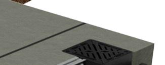

11 Typical Box Installation 10 11
12 Covers, Gratings & Flow Regulators Connection of Flow Regulators to Boxes The Flow Regulator should be fitted immediately after the Slotdrain channel has been connected to the silt box. Ensure that the semi-circular shaped orifice is at the bottom. At the position of the fixing holes either side of the wall plate, drill through the wall of the silt box and fix the unit with 2 x M12 concrete anchors or suitable bolts with a wing nut on the reverse side. Tape over any exposed section of thread on the bolt prior to backfilling with concrete. This will enable cleaner and quicker removal of the flow regulator for future maintenance. Connection of Flow Regulators to Constructed Catchpits The Flow Regulator should be fitted immediately after the Slotdrain channel has been connected to the silt box. Ensure that the semi-circular shaped orifice is at the bottom. At the position of the fixing holes either side of the wall plate, drill into the wall of the catchpit and fix the unit with 2 x M12 bolts.the fixings used should facilitate future removal of the flow regulator for maintenance.


13 Concrete Chambers (Cast in Situ & Precast) Gatic Slotdrain channels can be connected to concrete chambers, which may be constructed from concrete on site, or supplied to site as pre-cast units. The contractor should decide whether the channel units are installed first, with the concrete chamber formed around the Chamber Connector, or whether the concrete chamber should be formed first, with the channel installed after this. If the latter option is chosen, then a void should be left in the wall of the concrete chamber, to accept the Chamber Connector at a later time. This allows for greater fl exibility when installing the channel. Chamber Connectors should be used. Available to suit all channel sizes, these provide a seamless connection through the concrete wall of the chamber
14 Channel Protection Strip CastSlot Yellow - Treadsafe White - Non Treadsafe Yellow - Treadsafe White - Non Treadsafe UltraSlot White - Treadsafe White - Non Treadsafe White - Treadsafe White - Non Treadsafe


15 Drop Connectors These components provide a smooth transition between different sizes of Gatic Slotdrain channel, whilst the surface detail of the channel run remains the same. DIRECTION OF FLOW CHANNEL 'A' CHANNEL 'B' Note Coupling components at the socket (female) end of the channel will have to be removed in order to attach the Drop Connector unit. This is achieved by removing the joint-coupling rivet heads, with a hand-held mechanical cutting tool. Drop Connector 14 15


.")
.")
16 Connection Details Channel units are connected with a simple butt connection (pushconnection); no additional fixings are required. Units are fitted with connection collars at one end, which help locate and align channels during installation. Successive channel units should be pushed into these connection collars until a tight connection is achieved between channel sections. With Gatic Slotdrain, very precise connections can be achieved, improving the quality and finish of the installation, and reducing the risk of damage to channel units (no raised channel sections). If required, units can be moved together gently with a rubber paving hammer. Larger units are fitted with Location Plates, riveted to the inner walls of the channel (socket end). These also ensure accurate connection and location of channels when connected, and prevent the channel body from pinching inwards, during the main concrete pour. Slight adjustment of Throat Spacer Tags may be required to ensure a tight connection.

17 Taping Channels It is recommended that all joints between channel units and where channels meet Gatic boxes are taped prior to pouring the concrete surround. This is to prevent the ingress of concrete residue into the channel system. Installing Steel Reinforcement Concrete Surround Gatic s recommended steel reinforcing should be installed prior to concrete pouring, before channel units and Gatic boxes have been set in place and aligned. MESH REINFORCEMENT MESH MAIN BAR Ø MAIN BAR Crs. SECONDARY BAR Ø SECONDARY BAR Crs. B mm 100 mm 8 mm 200 mm B mm 100 mm 8 mm 200 mm GATIC SLOTDRAIN REINFORCEMENT MESH CODES CHANNEL WIDTH A15 - C250 D400 E600 F N / A N / A N / A B N / A N / A N / A B N / A N / A N / A B N / A N / A N / A B N / A N / A N / A B N / A N / A B785 B N / A N / A B785 B N / A B785 B x B


 These should be laid either side of the channel at 3m intervals (across the concrete")


18 Connection Details... continued Movement Joints For concrete pavement and other rigid surface installations, expansion joints should be installed between the channel concrete surround and the adjacent pavement. The position of movement joints should be considered on a project by project basis by the project engineer to ensure that the maximum lengths of concrete are not exceeded and that movement joints are not installed at weak locations within the system. Crack Control Joints (Crack Inducers/Shrinkage Joints) These should be laid either side of the channel at 3m intervals (across the concrete surround). This detail is required for all channel systems installed in a concrete pavement. Crack inducers should not be laid at element joints as this may result in weakness of the structural surround. Crack Control Joints can be formed in a variety of ways, including: Use standard expansion joint material Purpose made two-part plastic Crack Concrete surround can be cut with a disc cutting tool after the concrete has cured We would recommend the use of a Two-Part Top-Type Crack Inducer similar to the image right. These are pushed into the concrete surface during the pouring and smoothing phase, and the top section is removed after curing to leave a sealant void. Where Gatic boxes are installed, an expansion joint should be fitted around the outside of these units, between the concrete surround, around the frame and the adjacent pavement.


19 Formwork installation, Setting, Bedding The Formwork Method of installation is used if adjacent pavements are not yet in place, often when Gatic Slotdrain is to be installed in a new development. If the Gatic Slotdrain system and concrete surround is to be installed into an existing pavement area, it may be beneficial to use the Suspended Method of installation. Gatic Recommends a solid concrete base is laid to provide a level and solid base on which to set the channel units. Once the base has cured, channel units and boxes are set in place and aligned on the concrete base. Throat Protection Strip/Tape should be fitted around the channel at this point. A small amount of concrete may be applied around the Channel Feet to prevent movement. Concrete Base 18 19


20 Formwork installation, Setting, Bedding... continued Channel Preparation The trench should be wide enough to allow adequate working room, and the installation of steel reinforcing (if required). The minimum trench widths and the installation drawings are shown on page 6. Prepare two metal support bars and hook bolts for each Slotdrain channel (further information regarding the accessories required is available from Gatic). First Concrete Pour To avoid floatation, channel units should be restrained as necessary, with additional weight applied to the top of the channel. Pour a C32/40 wet mix in two separate pours, with the first pour being placed to a depth of 20mm below the underside of the Slotdrain body. The second pour should ideally be placed within 3 days of the first pour, following cleaning off of the laitance left on the top of the concrete from the first pour. Ensure the top edge of the channel is set below the adjacent pavement surface, in accordance with Gatic s recommendations. Erection of Formwork A formwork system is then erected on either side of the channel units. Timber props may be fitted between the throat section of the channel and the formwork inner wall, to maintain the horizontal position and straight alignment of channel units. There are two requirements that must be fulfilled for a forming a successful construction joint: the surface must be free from laitance (it is important to remove laitance - because of its high water content it is weak and porous, and will stop a strong watertight joint from being made with fresh concrete) and it should have an exposed aggregate finish. Secondly the fresh concrete must be placed and compacted so that it bonds properly to the prepared surface of the previously laid concrete. Surface preparation (usually undertaken 1-2 hours after pouring) and placing of the second pour within 3 days of the first pour ensures a good bond between the two layers. A properly placed and compacted wet mix of this grade ensures a structurally sound, homogenous concrete.


21 Note: Large Channels Concrete Pour In order to prevent upward movement of channels when pouring concrete, units will require weights placed on top of the channels. To control the pressure exerted on channel walls during concrete pours, when steel reinforcing is used in the channel concrete surround, we recommend that the concrete is poured in two phases. This decision should be taken by the project structural engineer, and is subject to their approval. Larger units can be braced across the channel body prior to concrete pours if deemed necessary. Whilst still wet, apply the specified surface finish for the concrete. The specified cross-fall and surface finish should be applied in accordance with the drawings provided. Two-part plastic Crack Control Joints can then be applied. Asphalt Finish If an asphalt surface is required, base material and asphalt layers can then be laid to the edge of the concrete surround. A small manual rolling machine should be used to compact the asphalt at the outer edge of the channel concrete surround, to avoid damage to the concrete edge. Compaction machinery should not be allowed to pass over the channel and channel concrete surround. Machines should be directed along each side of the channel concrete surround, running parallel to the concrete edge. Concrete Finish When the concrete has cured, the formwork system is dismantled, leaving the channel and concrete surround in place. Expansion material can then be attached to the concrete surround, and the adjacent concrete pavements can be laid up to the concrete surround. Pave Finish When the concrete has cured, the formwork system is dismantled, leaving the channel and concrete surround in place. The adjacent pavements can then be laid up to the concrete surround and the desired pavement finish added

22 Suspended Installation The Suspended Method of installation is used if the adjacent concrete pavements are already in place, often when a Slotdrain system is installed into an existing pavement area. If the Gatic Slotdrain system and channel concrete surround is required to be installed first; with the pavement installed afterwards, then the Formwork Method of installation should be used. Channel Positioning Safely lower each channel in to the prepared trench using appropriate lifting equipment. If reinforcing is required it should be placed and prepared in the trench before the slotdrain is positioned and aligned. Timber props may be fitted between the throat section of the channel and the trench inner wall, to maintain horizontal position and straight alignment of channel. Channel Preparation The trench should be wide enough to allow adequate working room, and the installation of steel reinforcing (if required). The minimum trench widths and the installation drawings are shown on page 6. Prepare two metal support bars and hook bolts for each Slotdrain channel (further information regarding the accessories required is available from Gatic). To ensure the top edge of the channel is set below the adjacent pavement surface, in accordance with Gatic s recommendations.


23 Longitudinal expansion joints should be fitted at this stage; these can be held in place by the timber props. Throat Protection Strip/Tape should be fitted at this stage to prevent ingress of concrete whilst pouring. First Concrete Pour To avoid floatation as necessary, channel units should be restrained, with additional weight applied to the top of the channel. Note: Large Channels Concrete Pour In order to prevent upward movement of channels when pouring concrete, units will require weights placed on top of the channels. To control the pressure exerted on channel walls during concrete pours, when steel reinforcing is used in the channel concrete surround, we recommend that the concrete is poured in two phases. This decision should be taken by the project structural engineer, and is subject to their approval. Larger units can be braced across the channel body prior to concrete pours if deemed necessary. Pour a C32/40 wet mix in two separate pours, with the first pour being placed to a depth of 20mm below the underside of the Slotdrain body. The second pour should ideally be placed within 3 days of the first pour, following cleaning off the laitance left on the top of the concrete from the first pour. There are two requirements that must be fulfilled for a forming a successful construction joint: the surface must be free from laitance (it is important to remove laitance - because of its high water content it is weak and porous, and will stop a strong watertight joint from being made with fresh concrete) and should have an exposed aggregate finish
24 Movement Joint Details Expansion Steel & Concrete There are a number of considerations to take into account regarding expansion and the installation of Gatic Slotdrain. Coefficient of Expansion The coefficient of thermal expansion for a material is a measure of how much that material will expand for each change in temperature of 1 degree. A table of commonly used materials and their expansion coefficients is set out below: Material Expansion (10-6 mm/k) Steel 13 Concrete 14.5 Polypropylene Polyethylene Polyester 123 *Steel has a similar expansion rate to concrete, so Gatic Slotdrain will expand and contract at a similar rate to the channel concrete surround, thereby minimising stresses caused by differential rates of expansion. Installation Movement Joints Please refer to the installation drawings and page 18 for details regarding the position of expansion joints. Longitudinal and Crack Control Joints (Crack Inducers/ Shrinkage Joints) may not be required for installations where asphalt or paving units (with sand filled joints) are the surface finish. This is because these surfaces are flexible and will move naturally when subject to temperature changes. Expansion joints may only need to be considered when the surfaces are rigid such as concrete pavements and paving units with cement joints. In such cases, expansion joints are required to protect the channel from lateral forces (exerted by expansion of the adjacent pavement), and to avoid cracking within the concrete surround due to shrinkage. We do not recommend that open expansion joints (left unfilled, with no expansion material) are used around Gatic Slotdrain channels. These can become filled with silt and debris over time, and then become ineffective. Movement Joint Material The type, material and thickness of expansion joints used to provide these construction joints should ultimately be the choice of the project engineer, as they are more familiar with site conditions and characteristics. Most products should be readily available (or easily sourced). The performance of the expansion joint product and material within the local environment should be assessed. The thickness of the expansion joint material used will depend on the anticipated rate of expansion, which is a factor of the temperature differential in the local environment, the type of concrete and aggregate used, the thickness of the concrete pavement, and the location and spacing of pavement expansion joints etc. There are many factors involved which may have an influence on the rate of movement of the concrete pavements adjacent to the channel. The expansion material used should be thick enough to cope with the anticipated movement and pressure exerted by the adjacent concrete pavements. Common expansion materials used are fibre-board and Semi Cross Linked Polyethylene (Large Cell) Expansion Material. We would not recommend that polystyrene is used, since this material does not regain its original dimensions once compressed.


25 Finishing Channel Concrete Surround Cross Fall Finishing Once the installation is complete, Throat Protection Tape or Strip should be removed, and the channel system should be flushed clean with water. The minimum cross fall towards the channel central slot is shown on the drawings provided. Installing Slotdrain in other surface finishes The surface material to be applied should be levelled appropriately. When using asphalt, this should be applied evenly around the channel throat area and levelled with a rake. A small rolling machine should then be used to compact the asphalt around the channel. It is important to note that compaction machinery should not be allowed to pass over the channel slot and throat area during rolling as this can damage the product. Machinery should be carefully directed along each side of the throat running parallel to the channel. The surface finish in the concrete (smooth or textured) should be specified by the project engineer. When installing a channel in adjacent paving materials, set the first block adjacent to the Slotdrain channel on a 15mm deep layer of polymer modified mortar, and surrounding materials in accordance with the paving supplier s instructions


26 Forming a Radius In some projects there may be a requirement to install the Gatic Slotdrain system to follow a given radius, for example around the perimeter of a taxiway on an airport project, or following the curve of a landscape feature. Gatic Slotdrain channel units are available in straight lengths of 500mm, 1m or 3m. Please refer to the tables on pages 28 and 29. for the achievable radius for standard channels in the range. When positioning channel units, a gap is formed between channels on the outside edge. All gaps between the channel joints, on both sides of the channel, should be sealed with a strong construction tape prior to concreting. Gradual Radii These can be formed using standard units, with each consecutive channel unit positioned at a slight angle in relation to the previous channel.

27 26 27
28 Forming a Radius... continued Gatic CastSlot & UltraSlot Minimum External Radius Channel Width Channel Length 1mm 2mm 3mm 4mm 5mm 6mm 7mm 8mm 9mm 10mm 100 3m 320.9m 160.5m 107.0m 80.3m 64.2m 53.5m 45.9m 40.2m 35.7m 32.1m 100 1m 107.0m 53.6m 35.7m 26.8m 21.5m 17.9m 15.4m 13.5m 12.0m 10.8m mm 53.6m 26.8m 17.9m 13.5m 10.8m 9.0m 7.7m 6.8m 6.0m 5.4m 150 3m 471.6m 235.9m 157.3m 118.0m 94.4m 78.7m 67.5m 59.1m 52.5m 47.3m 150 1m 157.3m 78.7m 52.5m 39.4m 31.6m 26.3m 22.6m 19.8m 17.6m 15.9m mm 78.7m 39.4m 26.3m 19.8m 15.9m 13.3m 11.4m 10.0m 8.9m 8.0m 225 3m 695.1m 347.7m 231.9m 173.9m 139.2m 116.0m 99.5m 87.1m 77.4m 69.7m 225 1m 231.9m 116.0m 77.4m 58.1m 46.6m 38.8m 33.3m 29.2m 26.0m 23.4m mm 116.0m 58.1m 38.8m 29.2m 23.4m 19.5m 16.8m 14.7m 13.1m 11.8m 300 3m 918.6m 459.5m 306.4m 229.9m 184.0m 153.4m 131.5m 115.1m 102.3m 92.1m 300 1m 306.4m 153.4m 102.3m 76.8m 61.5m 51.3m 44.0m 38.6m 34.3m 30.9m mm 153.4m 76.8m 51.3m 38.6m 30.9m 25.8m 22.2m 19.4m 17.3m 15.6m 350 3m m 534.9m 356.7m 267.6m 214.2m 178.5m 153.1m 134.0m 119.1m 107.2m 350 1m 356.7m 178.5m 119.1m 89.4m 71.6m 59.7m 51.3m 44.9m 39.9m 36.0m mm 178.5m 89.4m 59.7m 44.9m 36.0m 30.1m 25.8m 22.6m 20.2m 18.2m 400 3m m 610.7m 407.2m 305.5m 244.5m 203.8m 174.8m 153.0m 136.0m 122.4m 400 1m 407.2m 203.8m 136.0m 102.1m 81.8m 68.2m 58.5m 51.3m 45.6m 41.1m mm 203.8m 102.1m 68.2m 50.9m 41.1m 34.3m 29.5m 25.8m 23.0m 20.7m 500 3m m 761.4m 507.8m 381.0m 304.9m 254.2m 217.9m 190.7m 169.6m 152.7m 500 1m 507.8m 254.2m 169.6m 127.3m 102.0m 85.1m 73.0m 63.9m 56.9m 50.7m mm 254.2m 127.3m 85.1m 63.9m 51.2m 42.8m 36.7m 32.2m 28.7m 25.9m 600 3m m 908.5m 605.9m 454.6m 363.8m 303.2m 260.0m 227.6m 202.4m 182.2m 600 1m 605.9m 303.3m 202.4m 151.9m 121.7m 101.5m 87.1m 76.3m 67.9m 61.1m mm 303.3m 151.3m 101.5m 76.6m 61.1m 51.0m 43.8m 38.4m 34.2m 30.9m
29 Gatic CastSlot & UltraSlot Minimum Internal Radius Channel Width Channel Length 1mm 2mm 3mm 4mm 5mm 6mm 7mm 8mm 9mm 10mm 100 3m 320.8m 160.4m 106.9m 80.2m 64.1m 53.4m 45.8m 40.0m 35.6m 32.0m 100 1m 106.9m 53.5m 35.6m 26.7m 21.4m 17.8m 15.3m 13.3m 11.9m 10.7m mm 53.5m 26.7m 17.8m 13.4m 10.7m 8.9m 7.6m 6.7m 5.9m 5.3m 150 3m 471.5m 235.7m 157.1m 117.8m 94.3m 78.5m 67.3m 58.9m 52.3m 47.1m 150 1m 157.2m 78.6m 52.4m 39.3m 31.4m 26.2m 22.4m 19.6m 17.4m 15.7m mm 78.6m 39.3m 26.2m 19.6m 15.7m 13.1m 11.2m 9.8m 8.7m 7.9m 225 3m 694.9m 347.4m 231.6m 173.7m 139.0m 115.8m 99.2m 86.8m 77.2m 69.5m 225 1m 231.6m 115.8m 77.2m 57.9m 46.3m 38.6m 33.1m 28.9m 25.7m 23.2m mm 115.8m 57.9m 38.6m 29.0m 23.2m 19.3m 16.5m 14.5m 12.9m 11.6m 300 3m 918.3m 459.2m 306.1m 229.6m 183.7m 153.0m 131.2m 114.8m 102.0m 91.8m 300 1m 306.1m 153.1m 102.0m 76.5m 61.2m 51.0m 43.7m 38.3m 34.0m 30.6m mm 153.1m 76.5m 51.0m 38.3m 30.6m 25.5m 21.9m 19.1m 17.0m 15.3m 350 3m m 534.5m 356.3m 267.2m 213.8m 178.2m 152.7m 133.6m 118.8m 106.9m 350 1m 356.3m 178.2m 118.8m 89.1m 71.3m 59.4m 50.9m 44.5m 39.6m 35.6m mm 178.2m 89.1m 59.4m 44.5m 35.6m 29.7m 25.5m 22.3m 19.8m 17.8m 400 3m m 610.3m 406.8m 305.1m 244.1m 203.4m 174.3m 152.5m 135.6m 122.0m 400 1m 407.2m 203.4m 135.6m 101.7m 81.4m 67.8m 58.1m 50.9m 45.2m 40.7m mm 203.8m 101.7m 67.8m 51.3m 40.7m 33.9m 29.1m 25.4m 22.6m 20.3m 500 3m m 760.9m 507.3m 380.5m 304.4m 253.6m 217.4m 190.2m 169.1m 152.2m 500 1m 507.8m 253.6m 169.1m 126.8m 101.5m 84.5m 72.5m 63.4m 56.4m 51.2m mm 254.2m 126.8m 84.5m 63.4m 50.7m 42.3m 36.2m 31.7m 28.2m 25.4m 600 3m m 907.9m 605.3m 454.0m 363.2m 302.6m 259.4m 227.0m 201.8m 181.6m 600 1m 605.9m 302.6m 201.8m 151.3m 121.1m 100.9m 86.5m 75.7m 67.3m 60.5m mm 303.3m 151.9m 100.9m 75.7m 60.5m 50.4m 43.2m 37.8m 33.6m 30.3m 28 29
30 Positioning Access Units Gatic Slotdrain channel system will require access units to be placed in strategic locations along the channel run, to provide access into the system for cleaning and maintenance. The position of access units should be determined by the client and project engineer, taking into account the maintenance equipment that will be used. Specifiers may consider the following: Access units should be placed at the start of every channel run. Access units should be placed at every corner, or at the point where the channel changes direction mm Wide Channels: Mid-run access units should be placed every 30-50m mm Wide Channels: Mid-run access units should be placed every m. For short channel runs of 10m long or less, channel end-caps may be sufficient at the start of the channel run, as cleaning can be carried out from the catch pit end. Further advice and information is available from Gatic regarding the positioning of access units. An access unit should always be placed in corner positions Catch pit can be used as an access point for cleaning and rodding Midpoint access unit (in line) Access units should always be placed whenever a channel changes direction An access unit is always positioned at the start of channel These are guidelines only each project should be individually assessed regarding placement of access units. An access unit is always positioned at the start of channel

31 Cleaning and Maintenance Gatic Slotdrain channels should be inspected regularly to ensure that the system continues to operate effectively, and is free from damage and blockage by debris or solid objects. The system should be cleaned at least once a year, and incorporated into a planned maintenance schedule. The frequency of inspection and maintenance depends on the local environment and conditions. Channel units can be cleaned through the use of a high-pressure hose. This can be fed into the channel system through access units strategically placed along the channel run (see p30, Positioning Access Units ). The throat section of channel units should be kept clear at all times to ensure uninterrupted flow of water into the drainage channel. Any debris within the throat should be removed. The seating areas for covers and grates should be cleaned before they are replaced. The covers and grates should be locked into position to prevent these being removed, stolen or dislodged by traffic. Locking bolts should be replaced and sufficiently tightened, taking care that the bolt heads do not stand above the top surface of the cover or grate. If grates/ covers are allowed to move within their frame, this may cause damage to the frame or seating

32 Design Service Customised software - digital service. With the hydraulic calculator, a state-of-the-art development software, our partner company is offering the perfect tool for you to plan your line drainage system. All of your planning using just a single tool. The user-friendly program guides you through the whole planning process to ensure all your project requirements are met. It is hardly surprising that this software is already being used around the world for the most advanced surface drainage models. And best of all: you can get the software for free from After registering with MyGatic, you can then download the software in the download area or simply send us an to request the planning tool. Gatic Slotdrain channel with graphical user interface and 3D view


33 BIM data: Because the most innovative line drainage merits the most efficient planning. BIM data for all products of the Gatic system are of course also available for computer-aided planning. But data is not merely data. Here too we are offering you ultimate user-friendliness and maximum efficiency: Low amount of data despite extreme precision (LOD/LOI ) Line lengths easy to adapt Gratings can be selected and viewed visually including slot covers Automatic positioning of the channel including grating on the surface End plates can be chosen with or without outlet Concrete casing for clash detection, material consumption provided for excavation and amount of concrete per load class Item numbers of the channels and covers Links to homepage for additional information about installation, system, declarations of performance Screenshot of BIM database 32 33


34 BG-Graspointner GmbH & Co KG Gessenschwandt Oberwang AUSTRIA Tel.: / Fax: / Web: Your partner for BG drainage systems BG