Drainage and Retention of Water by Cladding Systems
|
|
|
- Andrea Adams
- 5 years ago
- Views:
Transcription
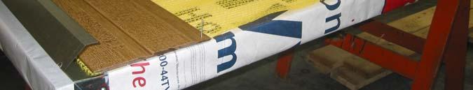
1 Drainage and Retention of Water by Cladding Systems BEST 1 Session M11: CLADDING Managing Moisture 12 June 2008 Don Onysko Constance Thivierge DMO Associates FPInnovations Silvio Plescia Bary Craig CMHC CMHC
2 The Ying and Yang of Moisture in Wall Systems Water, taken in moderation, never hurt anybody ---- Mark Twain Water ruins everything ---- Greg Allen (property manager)
3 Drainage and Retention of Water by Cladding Systems CMHC funded project to learn about the ability of some cladding systems to handle rain penetration through cladding. Project Managers - Barry Craig and Silvio Plescia Conducted at the Forintek Canada Corp. laboratory in Ste- Foy Quebec. Industry Advisor - Constance Thivierge
4 Drainage and Retention of Water by Cladding Systems Outline Intent of the testing How was it done What have we learned for the different systems
5 Drainage and Retention of Water by Cladding Systems Inner wall behavior relatively well understood Outer wall behavior is more of a challenge and has occupied more of our concerns in recent years because of systemic building failures. The difficulty lies in the complexity of response to the outdoor environment. We are guessing about most of those conditions.
6 Drainage, Retention and Drying of Cladding Systems If water penetration occurs, is our concern for the durability of the underlying wall, or for the cladding? BOTH have to be addressed Retained water creates conditions for a potentially damaging micro climate inside the wall, so its quantity and location, and the ability of the system to dissipate that moisture are key to durability of specific systems.
7 Drainage and Retention - Why Do It? Cladding systems and rain penetration Face Sealed (some work) Not Face Sealed (most work, somehow) Direct Applied Drained CMHC s Interest was in the performance of systems that are not face sealed, systems that are expected to manage water penetration to the WRB.
8 Drainage, Retention and Drying of Cladding Systems Systems tested EIFS, vinyl, hardboard, wood and fiber cement siding. Direct-applied siding No Intentional provision for Drainage Drained Cladding provision of intentional drainage.
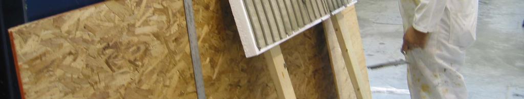
9 Drainage, Retention and Drying of Cladding Systems How was it done?? Simply. Pour water behind siding Observe drainage Observe weight gain Observe drying Ponder results


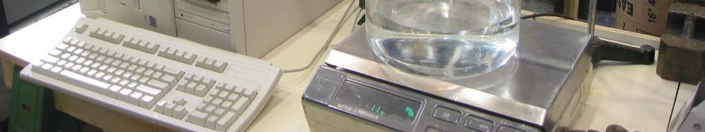
10 Monitoring Weight Gain Balance Beams


11


12


13


14


15 Load cell centered under wall
16 Drainage, Retention and Drying of Cladding Systems Test Protocols Water was supplied to each test wall at 8 litres/hour for one hour, 24 wide path. The drain period (so-called) was one additional hour Wall weight was monitored throughout for an additional 2 days at isothermal conditions. [23º C, 50% RH] Additional tests, moisture mapping, air flow
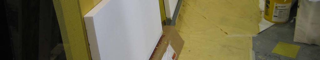
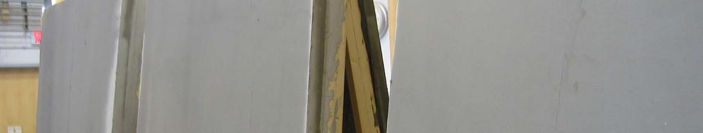
17 Drain, Retain and Dry EIFS (6 walls 3 manufacturers) Vinyl siding (3 walls 2 profiles) Hardboard siding (3 walls 2 profiles) Wood Siding (3 walls 2 profiles) Fiber reinforced siding (2 walls one profile) One wall with battens, three walls had drainage mats. Building paper and SBPO WRB were both represented. Some walls were tested in different ways and some tests were repeated.
18 Presentation of Results EIFS walls test results Vinyl wall test results All other siding wall test results Comparisons between systems Concluding comments


19


20


21


22
23 Drainage Results EIFS walls - Front All Wall Tests - Drainage Down Front of Drainage Cavity (EPS) Change in Weight (g) Time (min) Wall 1 - Front Wall 2 - Front Wall 3 - Front Wall 4 - Front Wall 5 - Front Wall 6 - Front
24 Drainage Results EIFS Walls - Back All Wall Tests - Drainage Down Back of Drainage Cavity (WPB) Change in Weight (g) Time (min) Wall 1 - Back Wall 2 - Back Wall 3 - Back Wall 4 - Back Wall 5 - Back Wall 6 - Back
25 Including 48-hr drying period - Front All EIFS Walls - Drainage Down Front of Drainage Cavity (EPS) 2-hr plus 48-hr test Change in Weight (g) Time (hr) Wall 1 - Front Wall 2 - Front Wall 3- Front Wall 4 - Front Wall 5 - Front Wall 6 - Front
26 Including 48-hr drying period - Back All EIFS Walls - Drainage Down Back of Drainage Cavity (WPB) 2-hr plus 48-hr test Change in Weight (g) Time (hr) Wall 1 - Back Wall 2 - Back Wall 3 - Back Wall 4 - Back Wall 5 - Back Wall 6 - Back
27 EIFS Observations Water input was well directed to the bottom of the wall without much lateral dispersion. Retained water at 2-hr 2 was 75 g (average of 12 tests) 99% drained Average Retained water at 50 hours was 42 g. Drying was related to air flow resistance of starter tracks which controlled the rate of ventilation by moisture buoyancy for some walls.
28 Profiles of Vinyl Siding Tested Profile #1 Profile #2


29 Vinyl test walls drainage from joints and drain holes
30 Results Vinyl Siding Walls 2-hr Wetting/Drainage Period - Vinyl Walls 1, 2, and Weight Change (g) Time (hr) Vinyl 1 Vinyl 2 Vinyl 3
31 Vinyl Siding Walls 50-hr Wetting/Drying Period - Vinyl Walls 1, 2, and Weight Change (g) Time (hr) Vinyl 1 Vinyl 2 Vinyl 3
32 Vinyl Walls - Observations Rate of water input was higher than the ability of drain holes to pass the water, hence a head of water was built up. Side leakage resulted in less valid tests because some water was absorbed by the wood frame. Siding profiles depend on build-up of water head to allow water to drain through the drainage holes. Average retained water was 275 g (2-hr) and 183 g (50-hr). 96% drainage. Free water stored spilled on floor when walls were dismounted from the weighing apparatus (at the end of the 50 hr test) Very slow drying of retained water was found. These vinyl siding walls were direct applied did not allow the water to drain behind the siding, Storage and drainage of water was close to where water was input.


33 Profiles of wood, hardboard and fibre-cement siding H1 H2 W1 W2 CF


34 Drainage tests on DIRECT APPLIED hardboard and wood siding


35 Drainage tests W1-3, FC-1 Wood Siding on Mat 3 Direct Applied fiber cement board
36 Results - Direct applied siding Wood, Hardboard and fibre-cement Direct-Applied Siding Tests 2-hr Wetting/Drainage Phase Weight Change (g) Time (minutes) CF-1 CF-2 Wood W2 DA H1 - DA - Retest H1 - DA
37 Results - Direct applied siding Wood, Hardboard and fibre-cement Direct-Applied Siding Tests 50 hr Wetting/Drying Phase Weight Change (g) Time (hours) CF-1 CF-2 Wood W2 DA H1 - DA - Retest H1 - DA
38 DIRECT APPLIED wood, hardboard and cement fibre siding walls - Observations Most water drained out close to where it was input through siding joints, because the siding was direct applied and restricted drainage behind the siding. The wood siding that was direct applied was not intended to be installed that way. It held the most water. (94.7% drainage). The other direct applied siding walls behaved similarly and exhibited retention largely dependent on absorption ability. Drying ability was strongly related to the vapour permeance (air permeability) of the lap joints in the siding.


39 Drainage mat types M1 M2 M3


40
41 Results Wood and hardboard siding on drainage mats and batten strips All Walls with Distinct Drainage Planes 2-hr Wetting/Drainage Phase Weight Change (g) Time (minutes) H2 - MAT 1 Back H2 - MAT 2 Back H2 - MAT 1 Front H2 - MAT 2 Front Wood WI - Mat 3 Wood W2 - Battens
42 Wood and hardboard siding on drainage mats and furring strips All Walls with Distinct Drainage Planes 2-hr Wetting/Drainage Phase Weight Change (g) Time (hours) H2 - MAT 1 Back H2 - MAT 2 Back H2 - MAT 1 Front H2 - MAT 2 Front Wood WI - Mat 3 Wood W2 - Battens
43 Drainage of Walls with drainage mats - Observations Drainage mats disperse water falling through the mat and wetting takes place throughout the wall. Relatively large retention, likely in the joints of the siding and slower drying was found (higher retention ratio) Most siding systems are not designed to shed water on the back side only the front. Hence they are susceptible to collecting water in joints and be held there by capillarity. Traditional batten strips worked well, even though initial absorption into end grain was high. Drying rates were related to the air flow characteristics of the ventilation cavity, although both the ventilation cavity and the siding joints contributed to drying.
44 Vinyl Wall Siding vs EIFS Change in Weight (g) Time (min) EIFS 1-F EIFS 2-F EIFS 3-F EIFS 4-F EIFS 5-F EIFS 6-F EIFS 1-B EIFS 2-B EIFS3-B EIFS 4-B EIFS 5-B EIFS 6-B Vinyl 1 Vinyl 2 Vinyl 3
45 Drainage Tests - Direct-applied siding (Vinyl + CF + H + W) Compared with EIFS Change in Weight (g) Time (min) EIFS 1-F EIFS 2-F EIFS 3-F EIFS 4-F EIFS 5-F EIFS 6-F EIFS 1-B EIFS 2-B EIFS3-B EIFS 4-B EIFS 5-B EIFS 6-B Vinyl 1 Vinyl 2 Vinyl 3 CF-1 CF-2 H1 - DA Wood W2 - DA
46 All Tests with drainage cavities (EIFS + siding with mats) Change in Weight (g) Time (min) EIFS 1-F EIFS 2-F EIFS 3-F EIFS 4-F EIFS 5-F EIFS 6-F EIFS 1-B EIFS 2-B EIFS3-B EIFS 4-B EIFS 5-B EIFS 6-B H2 - MAT 1 Back H2 - MAT 2 Back Wood WI - Mat 3 Wood W2 - Battens
47 Conclusions EIFS walls EIFS walls retained the least water. Their drying ability was related to the air flow characteristics of the drainage cavity and starter tracks with open venting at the top of the wall. Field installations are usually closed off at the top. EIFS walls with adhesive ribbons directed water to the base of the wall with little spread. Water retention in butt joints in the EPS insulation seemed to occur for one EIFS wall. It retained more water and dried more slowly.
48 Conclusions Vinyl siding walls Direct Applied Vinyl siding tended to restrict the rate of drainage a limit controlled by the size and number of drainage holes provided. Vinyl siding walls retained water in liquid form and drying was very slow. This correlated with the low air (and vapour) permeance of the joints in the siding. In practice, longitudinal air flow can take place. Drainage took place through small drainage holes close to the level at which water was introduced. For newly built walls with no nail popping, the installation did not allow drainage behind the siding even though codes refer to this cladding as loosely applied.
49 Conclusions Direct-applied siding Direct applied hardboard and fiber cement board siding drained water close to where the water was introduced behind the siding. Drying was related to the air and vapour permeance of the siding joints. The amount of retained water was lower but it was likely held at the line of contact between the siding and the wall. While the overall retained water may be low, the concentration at a few joints could be high. Direct applied wood siding retained the most water and dried slowly but the profile selected was not recommended for direct application. This case was selected to demonstrate a poor practice. Most siding profiles are not designed to facilitate drainage from behind the cladding. It happens but could be made to drain better. Chronic wetting would be of more concern for direct-applied siding because of the location where water is presumed to be held.
50 Conclusions Siding with a drainage cavity (1) Siding systems installed on drainage mats (or batten strips) allowed water to drain well to the bottom of each test wall. But this allows a greater inner surface area of wall to be wetted. When wetting takes place on the back of siding, drainage taken place through joints depending on the design of the siding, and the number of joints involved depends on the rate at which water enters. The hardboard siding had a profile that could restrict some water entry into joints from the back. But, this was not observed directly.
51 Conclusions Siding with a drainage cavity (2) The drainage generally took place without draining through the joints, with one exception. Mat 3 (designed for installation under roof shingles had tapered dimples that likely directed more water against the back of the siding. The wood siding was not designed to shed water down the back, and allowed some water to drain out through joints. The mats allowed more extensive wetting and greater retention resulted. It was inferred that water was held in siding joints by capillarity since drying was relatively slow. Batten strips can absorb large amounts of water in end grain; this suggests that the ends should be sealed. They can also dry rapidly.
52 Overall Conclusions We ve learned how some siding systems handle water that is introduced behind the cladding Location of concentration of retained water was not known, but was inferred. In some cases, water was likely held at the interface between the siding and the wall so there would be some concern for chronic wetting In other cases, water was likely held away from the basic wall. There might be some concern for the durability of the siding where that moisture was held. The drainage mats dispersed water as it dropped down in the space provided, but it was largely held in joints because drying was slow. The test approach used can be used to develop siding systems that drain water well and retain less of the water that penetrates behind siding.
53 Drainage and Retention of Water by Cladding Systems Thanks for your attention