Ideas for the Next Generation VLA Radio Telescopes
|
|
|
- Melina Turner
- 5 years ago
- Views:
Transcription

1 Ideas for the Next Generation VLA Radio Telescopes Array-able larger antennas Prior work done by others to show optimum sizes for best overall cost is usually in the 10-18m size range, needs a re-run for NGVLA? 1701, rue Chicoine, Vaudreuil-Dorion, Quebec, Canada, J7V 8P2 Tel: Fax: info@intertronicsolutions.com
2 Background on InterTronic Solutions 1701, rue Chicoine, Vaudreuil-Dorion, Quebec, Canada, J7V 8P2 Tel: Fax:


3 Our facilities and capabilities We are based in Vaudreuil-Dorion Canada We have in house full mechanical design capabilities for structural, thermal, FEA analysis of our designs We have in house software design for antenna pedestal system control We have in house RF and system design and project management expertise We have an extensive network of expert consultants we use for special feed or antenna optics design We have a qualified network of existing subcontractors for manufacturing our major components

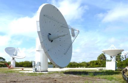
4 InterTronic designs and manufactures a range of precision antenna systems presently with reflectors from 2m to 12m in diameter for use up to over 40 GHz 20 GHz smaller systems Our new 12m 40 GHz VGOS/VLBI rated system
5 Our understanding of NGVLA plans GHz (or GHz) 5 x VLA collecting area (or 10x) This = approx. 590 x 12m sized antennas (or ~1180 x 12m) 260 x 18m sized antennas (or ~ 520 x 18 m) Clearly the overall system costs needs to be looked at in detail to establish the best size for this application. Best being defined as acceptable for the science goals and then the lowest cost (Capex and Opex) overall approach. A re-run of some of the past trade off studies for this particular application seems needed, which in turn will need antenna price estimates for various sizes. We would be happy to help with these.
6 There are several factors to consider for overall lowest installed telescope system cost: The antenna system design and materials choices that drives the basic factory / manufacturing cost. Reflector design For use to 100 GHz this will need surface/panels accuracies in the inch RMS range Pedestal design at 12-18m this gives pedestal bending in wind requirements of less than a few milli-degrees Control system design Use COTS equipment. Astronomy grade interfaces, milli-degree pointing Logistics and transportation issues, location and available materials and services Proportion of assembly needed in the field Foundation requirements
7 Additional specifications that can drive system cost. (Apart from frequency and array size.) Operational and survival wind speeds vs pointing accuracy vs 24/7 operation Slewing speed requirements Requirements for heavy or complex feed systems, fancy offset geometries Arraying requires antennas with predictable/stable properties such as: Stable path lengths Stable / accurately modelable reference point positions Good wind resistance
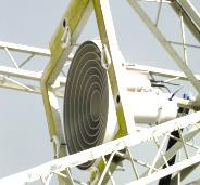
8 Reflector design options For 100 GHz applications that demand high accuracy surfaces (0.003 inch RMS = 0.45 db loss) the choices are limited for outdoor systems. Single piece is impractical and not accurate enough at this size, no matter what it is made of Panelized systems with high accuracy panels are the obvious and proven choice. If the systems were in radomes then a simpler reflector and lower cost pedestal design can be considered but the cost of large radomes is almost equal to the antenna system cost. Viable panel manufacturing techniques include metal machined from solid, metalized CFE structural panels, precision stretch formed panels. All requiring precision panel adjusters --- Our suggested technique is high accuracy, reinforced, stretch formed panels.
 panel")

9 Our in house (US) panel stretching and fabrication.


10 We are presently achieving RMS panels --- with some further work this could be reduced to 0.002


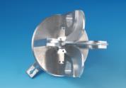
11 Our subreflector designs, these can suit compact cassegrain or ring focus designs, -- accuracy around inch RMS Carbon fiber high accuracy subreflector High Accuracy Hexapod


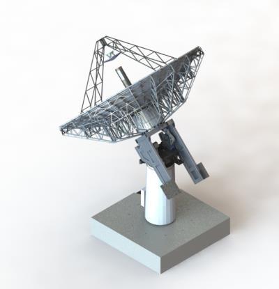
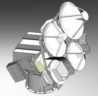
12 Reflector design options, our recommended approach 100 precision adjustable panels for 12m, maybe 180 for 18m? Stiff backing structure


13 Our reflector design provides a large accessible rear hub space Full sized person!


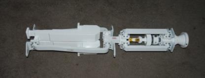
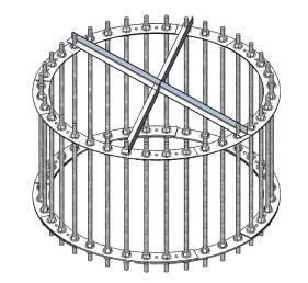
14 Very stiff but simple (low cost) pedestal. For up to 12m systems this is container shippable Accurately machined strong one piece weldment turning head


15 Massively oversized main bearings -- for long life
16 Build in Corrosion protection Fully hot dip galvanized and painted steel parts, including the pedestal Stainless hardware where possible Galvanic protection between St Steel and Aluminum parts Full Air conditioning inside the pedestal, eliminate internal condensation and also used to stabilize the system height for a stable ref point All of the above extends routine maintenance work cycles considerably
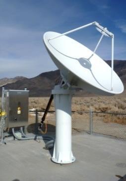
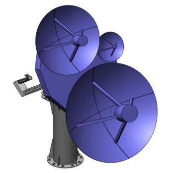
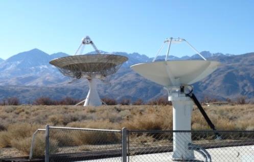
17 Our present 12m sized systems Main reflector surface comprises 100 precision adjustable stretch formed aluminum panels Carbon fiber composite sub-reflector with optional high accuracy hexapod adjustment mechanism Precision zero backlash torque biased mechanisms based on COTS motors and controllers Extensively galvanized and painted to assist with corrosion protection, galvanic protection built in by design Meets all the VGOS/VLBI2010 specifications Suitable for array applications

18 Typical simple foundation


19 Method of construction For small quantities Build reflectors on site out in the open -- and live with weather constraints For large quantities Erect low cost shelter / steel building - allowing 24/7 assembly