May 1, THE CORRADINO GROUP 4055 N.W. 97 th Avenue Miami, Florida Mr. Carlos E. Verson, P.E. Project Manager
|
|
|
- Julius Lambert
- 5 years ago
- Views:
Transcription
1 May 1, 213 THE CORRADINO GROUP 455 N.W. 97 th Avenue Miami, Florida Attention: Mr. Carlos E. Verson, P.E. Project Manager Re: Report of Geotechnical Engineering Services - Roadway Soil Survey Bird Avenue from U.S.1 to Aviation Avenue PSI Project No.: Dear Mr. Verson: Professional Service Industries, Inc. (PSI) has completed a geotechnical engineering study in connection with the noted project. Our services were provided in general accordance with PSI Proposal No , dated January 11, 212 Authorization to proceed was by means of Work Order No. 1, dated February 29, 212. The Work Order relates to our Miscellaneous Civil Engineering Services contract for the City of Miami with The Corradino Group. 1. PROJECT INFORMATION The subject roadway segment extends along Bird Avenue from U.S.1 to Aviation Avenue in. A site vicinity map identifying the limits of the study is presented on Sheet 1 of the Appendix. As we understand, the project will involve improvements along approximately 4,2 linear feet of roadway. The improvements will consist of milling and resurfacing between U.S. 1 and Mary Street. Roadway re-construction is planned between Mary Street and S.W. 27 th Avenue. In addition, the development will consist of new drainage (i.e. exfiltration trench system). Currently, Bird Avenue exists with two lanes of traffic flow (one in each direction) in the eastwest direction, passing through a predominantly residential neighborhood. The existing right-ofway along the roadway is covered by asphaltic pavement, concrete sidewalk, exposed granular fill, grass and trees. Photographs from our site visit are presented on Sheet 2 of the Appendix. If any of the noted information is incorrect or has changed, please notify PSI so that we may amend the recommendations presented in this report, if appropriate. Professional Service Industries, Inc. 795 N.W. 64 Street Miami, FL / Fax 35/ FL Engineering Business 3684
2 Bird Avenue from U.S.1 to Aviation Avenue Page 2 PSI Project No.: FIELD AND LABORATORY TESTING 2.1 STANDARD PENETRATION TEST (SPT) BORINGS To evaluate subsurface conditions at the site, we drilled/sampled 11 Standard Penetration Test (SPT) borings to depths ranging from approximately 2 to 15 feet below grade. The SPT Borings were drilled using the techniques of ASTM D-1586 and performed at the approximate locations shown on Sheets 3 through 9 of the Appendix. After seating the sampler six inches, the number of successive blows required to drive the sampler twelve inches into the soil constitutes the test result commonly referred to as the "N" value. The N value has been empirically correlated with various soil properties and is considered to be indicative of the relative density of cohesionless soils and the consistency of cohesive soils. The SPT borings were performed using CME-55 and CME-75 trucks mounted drill rigs equipped with automatic hammers. The recovered split spoon samples were visually classified in the field and transported to the laboratory for further review. The boring locations were marked in the field using the available plans with reference to existing site features. Plane coordinates data was collected at each boring location using a hand held GPS instrument (Garmin 6 CSX) with the reported data being accurate to within 1 feet. The plane coordinates and groundwater table data are tabulated on Table 1 of the Appendix. Utility clearances were coordinated by PSI and updated as required. During field explorations, flagmen, barricades, cones and sign devices were used as necessary in compliance with the applicable FDOT Roadway and Traffic Design Standards (Index 6 series). After completion of the borings, the boreholes were backfilled, the asphaltic surface patched where necessary and the site was generally cleaned, as required. Performing our field work required obtaining various permits from the City of Miami (i.e. right-ofway, excavation, parking authority and police). 2.2 PERCOLATION TESTS PSI performed four percolation tests at depths of 15 feet below grade within SPT borings B-2, B-4, B-7 and B-8. The percolation tests were performed in general accordance with the South Florida Water Management District (SFWMD) procedures for the "Usual Condition Constant Head" Percolation Test. SPT sampling was performed simultaneously as the boreholes were advanced using a 6-inch diameter casing. A 4-inch diameter perforated PVC pipe was placed in the borehole prior to retrieving the casing. Water was then pumped into the borehole in order to raise the water level as close to the ground surface as possible. Once the inflow equalized with the outflow rate, the average pumping rate and level of the water for this stabilized flow rate was recorded. The hydraulic conductivity values determined from the tests are presented in Table 2 of the Appendix. The values are in units of cubic feet of flow per second, per square foot of seepage area, per foot of head (cfs/ft 2 -ft). The tabulated values are ultimate values. The designer should apply an appropriate factor of safety.
3 Bird Avenue from U.S.1 to Aviation Avenue Page 3 PSI Project No.: PAVEMENT CORES PSI collected a total of six, six-inch diameter pavement cores for this project. The pavement core locations for this task were selected by PSI so as to adequately identify pavement section thicknesses in the area. Additionally, PSI performed SPT sampling below the extracted pavement core level. Photographs of the pavement core and the sampling location are included within the Pavement Core and Site Photographs sheets (Sheets 1 through 15 of Appendix). Upon completion of field testing the resulting boreholes were sealed using a cold bitumen patch and the site was generally cleaned, as required. 3. GENERALIZED SUBSURFACE CONDITIONS 3.1 GENERAL Based on the results of the field and laboratory testing program, the near surface soils along the project alignment have been grouped into four different strata as noted in the Table shown below. Each stratum group exhibits a range of engineering properties related to suitability for roadway construction as outlined by FDOT Standard Index 55. The soil types encountered at the boring locations are presented in the form of detailed individual logs in the Appendix. The general stratification presented below is based on visual observation of the recovered soil samples and the interpretation of field logs by a geotechnical engineer. Included with the profiles are the N-values and groundwater levels measured at the time the borings were drilled. STRATUM SOIL DESCRIPTION DEPTH (FEET) THICKNESS (FEET) AASHTO FROM TO 1 Asphalt Light Brown/Gray LIMEROCK with Fine Sand to 6. A-1-a/ A-1-b 3 Light Brown/Gray Fine SAND to 6. A-3 4 Light Brown/Gray LIMESTONE with Fine Sand to GROUNDWATER CONDITIONS At the time of our field exploration, the groundwater table where encountered was at depths ranging from 7.8 to 8.8 feet below grade. The groundwater table, when not encountered has been noted as N.E. The depths to groundwater table are noted on Table 1 of the Appendix. It should be noted that groundwater levels fluctuate seasonally as a function of rainfall, and the infiltration rate of the soil. Therefore, at a time of year different from the time of drilling, there is a possibility of a change in the recorded levels. It should also be noted that our field explorations were performed during relatively dry periods. Therefore, the estimated seasonal high groundwater (ESHGWT) for the site should be expected to be about 18 inches higher than the levels measured during our study. We recommend that the contractor determine the actual groundwater levels at the time of construction to assess groundwater impact on the construction procedure.
4 Bird Avenue from U.S.1 to Aviation Avenue Page 4 PSI Project No.: ENGINEERING EVALUATION AND RECOMMENDATIONS (ROADWAY RECONSTRUCTION) 4.1 SOIL USAGE SUMMARY The subsurface materials are generally considered suitable and are not expected to impose geotechnical constraints or limitations on the planned roadway improvements, provided the subgrade is prepared prior to placement of the new pavement. 4.2 SUBGRADE PREPARATION The exposed roadway subgrade should be proofrolled until compaction is achieved to a depth of 12 inches below the working surface. Pumping, cracking and other unusual distortion of the surface under the weight of the roller is indicative of underlying pockets of soft soils which should be removed over the width of the proposed pavement and shoulders plus a foot on each side and replaced with structural fill in accordance with Florida Department of Transportation (FDOT) Index 55 and the latest FDOT Standard Specifications for Roads and Bridge Construction. 4.3 STRUCTURAL FILL REQUIREMENTS Structural fill, if used (to achieve the final pavement grades) should consist of materials conforming to FDOT Standard Index 55. In general, the structural fill to be placed in pavement backfill areas should consist of inorganic, non-plastic, clean sand or limerock free of any manmade debris. The fill materials should contain less than 1% percent material passing the No. 2 mesh sieve. The maximum particle size of the limerock should not exceed three inches. The structural fill to be compacted with a heavy vibratory roller should be placed in lifts not exceeding twelve inches in loose thickness. The structural fill to be compacted with a vibratory plate, or a small walk-behind vibratory roller should be placed in lifts not exceeding six inches in loose thickness. Compaction requirements should be in general accordance with Section 12-9 of the FDOT Standard Specifications for Road and Bridge Construction. It is imperative that the fill supporting new pavements be placed, compacted and tested until the maximum density is achieved. The tests should be performed by a qualified Soils Technician under the supervision of a Geotechnical Engineer, in accordance with appropriate ASTM procedures. Any fill area indicating less than the recommended compaction should be recompacted until the required density is obtained prior to the placement of subsequent lifts. 4.4 PAVEMENT DESIGN CONSIDERATIONS The proposed new pavement area is understood to be a flexible asphalt concrete section. The pavement cross-section should include a base course consisting of limerock, with a minimum LBR value of 1 percent, meeting the requirements of the FDOT "Standard Specifications for Road and Bridge Construction", Section 911. The base material should overlie stabilized subgrade with a minimum LBR value of 4. In areas of LBR values less than 4, the subgrade should be stabilized to a depth of 12 inches. This can be achieved by blending base materials with the existing subgrade soils. Both the base course and stabilized subgrade should be compacted to at least 1 percent of maximum dry density (AASHTO T-99). Their thicknesses should be based on design requirements. Asphalt should be of Type S, with a thickness that is determined in the pavement design that considers the anticipated traffic loading.
5 Bird Avenue from U.S.1 to Aviation Avenue Page 5 PSI Project No.: Observing FDOT criteria, a minimum separation of three feet is recommended between the bottom of the pavement base and the estimated normal wet season groundwater table. The point of reference for this measurement would normally be the lowest point of the base. If the above minimum separation cannot be met, than the appropriate resilient modulus reduction factor should be used. From section of the Flexible Pavement Design Manual, when the base clearance is less than three feet, the pavement designer must reduce the Design Resilient modulus as noted on the following page: For two feet Base Clearance a 25% modulus reduction For one foot Base Clearance a 5% modulus reduction If one foot base clearance cannot be met the normal practice is the use of under-drains. 5. CONSTRUCTION CONSIDERATIONS 5.1 GENERAL ROADWAY CONSTRUCTION RECOMMENDATIONS The following are our recommendations for overall site preparation and mechanical densification, based on our exploration results and the anticipated construction. These recommendations along with those for Subgrade Preparation and Structural Fill requirements stated earlier should be used as guidelines for the Design Engineer preparing specifications. Site preparation and filling should be in accordance with sections 11 and 12 of the FDOT Standard Specifications for Road and Bridge Construction and FDOT Standard Indices 5 and The roadway reconstruction limits should be stripped and cleared of existing pavement, topsoil and any unsuitable materials (if encountered). A Geotechnical Engineer or representative should observe the stripped grade to document adequate depth of stripping, prior to backfilling and filling. 2. The stripped and compacted backfilled areas should be leveled sufficiently to permit equipment traffic, cut to grade if necessary, and then compacted using a large diameter, self-propelled or tractor drawn roller. The roller should be operated in static mode and be capable of exerting a minimum impact force of 15 tons. 3. Careful observations should be made during proofrolling to help identify any areas of soft yielding soils that may require over-excavation and replacement. Care should be used when operating the compactor near existing structures (including underground structures such as pipelines and residential buildings) to avoid transmission of vibrations that could cause settlement damage or disturb occupants. Use of a smaller vibratory or static compactor may be necessary in some instances. Construction operations that may be affected by vibration, such as concrete placement, if any, should be scheduled at times when nearby compaction operations are not taking place. 4. Prior to any field construction operations, we recommend that a survey be performed (including pictures and/or video) of existing structures located adjacent to the existing right-of-way. Documentation should be made of any foundation problems or structural distress noted by owners. If any problems are evident or substantial objections voiced by property owners, consideration should be given to monitoring vibrations during compaction. It is also recommended that a follow-up photographic and visual survey be performed after the compaction operations.
6 Bird Avenue from U.S.1 to Aviation Avenue Page 6 PSI Project No.: Prior to beginning compaction, soil moisture contents may need to be controlled in order to facilitate proper compaction. If additional moisture is necessary to achieve compaction objectives, then water should be applied in such a way that it will not cause erosion or removal of the subgrade soils. A moisture content within two percentage points of the optimum indicated by the AASHTO test method T-18, Method C, is recommended 6. Earthwork and related operations should be conducted in accordance with Section 12 of the FDOT Standard Specifications for Road and Bridge Construction. 7. An experienced, qualified Geotechnical Engineer should be retained to provide on-site observation of earthwork activities. Monitoring should include the visual observation of stripping asphalt and topsoil, placement of approved fills, proof-rolling and compaction testing. Density tests should be performed in surficial fill material after proof-rolling and in each fill lift thereafter. It is important that careful observation be made to confirm that the subsurface conditions are as we have discussed herein, and that fill placement is in accordance with our recommendations, project specifications and the latest FDOT Standard Specifications for Road and Bridge Construction. 5.2 GROUNDWATER CONTROL During subgrade preparation, the soils below design grade could become disturbed by construction activities due to heavy rainfall conditions or temporarily perched water. If this becomes the case, the contractor may be directed by the owners representative to remove the disturbed or pumping soils to a depth of 12 to 18 inches below design grade and backfill the area with structural fill in accordance with FDOT Index 55 and the latest FDOT Standard Specifications for Roads and Bridge Construction. Surface water and groundwater control may be necessary during construction to permit establishment of a stable bottom. A section of the construction area could be dammed off, and water diverted through a temporary ditch or pumped around construction activities. If a pump is used, a standby pump is recommended. Depending upon shallow groundwater levels at the time of construction, seepage may enter from the bottom and sides of the excavation. Such seepage will act to loosen soils, and create difficult working conditions. Therefore, it may be necessary to wellpoint or sump pump and rim ditch the construction area. Groundwater levels should be determined immediately prior to construction. Shallow groundwater should be kept at least 24 to 36 inches below the lowest working area to facilitate proper material placement and compaction. 6. REPORT LIMITATIONS Our professional services have been performed, our findings obtained, and our recommendations prepared in accordance with generally accepted geotechnical engineering principles and practices. This company is not responsible for the conclusions, opinions or recommendations made by others based on these data. No other warranties are expressed or implied. The scope of the investigation was intended to evaluate soil conditions within the influence of the expected roadway pavement section.
7 Bird Avenue from U.S.1 to Aviation Avenue Page 7 PSI Project No.: The analysis and recommendations submitted in this report are based upon the data obtained from the soil borings performed at the locations indicated. If any subsoil variations become evident during the course of this project, a re-evaluation of the recommendations contained in this report will be necessary after we have had an opportunity to observe the characteristics of the conditions encountered. The applicability of the report should also be reviewed in the event significant changes occur in the design, nature or location of the proposed roadway reconstruction. The scope of our services did not include any environmental assessment or investigation for the presence or absence of hazardous or toxic materials in the soil, groundwater, or surface water within or beyond the site studied. Any statements in this report regarding odors, staining of soils, or other unusual conditions observed are strictly for the information of our client. This report has been prepared for the exclusive use of The Corradino Group and their design consultants, for the specific application to the design and construction Bird Avenue from U.S. 1 to Aviation Avenue in. 7. CLOSURE We trust this report is adequate for your current needs; however, should you have any questions or should additional information be required, please do not hesitate to contact our office at (35) Respectfully submitted, Professional Service Industries, Inc. Certificate of Authorization No: 3684 Gustavo A. Silva Paul D. Passe, P.E. Dhuruva (Drew) Badri, P.E. Project Specialist Chief Engineer Department Manager FL License No FL License No cc: Addressee (3 and PDF) File (1 and PDF) APPENDIX Sheet 1: Sheet 2: Sheets 3 through 9: Sheets 1 through 15: Table 1: Table 2: Site Vicinity Map Site Photographs Boring Location Plan Pavement Core and Site Photographs Log of Borings Summary of Test Locations Summary of Percolation Test Results Schematic of Usual Open-Hole Percolation Test P:\397 - Geo\213 PROJECTS\ Bird Avenue - US-1 to Aviation Avenue (The Corradino Group)\Report Documents\ Bird Avenue - US-1 to Aviation Avenue (The Corradino Group).doc
8 APPENDIX


9 SITE VICINITY MAP Approximate Site Location GEOTECHNICAL ENGINEERING SERVICES DATE: 4/26/213 DRAWN: JC SHEET No.: 1 PSI PROJECT No.: CHKD:: CD
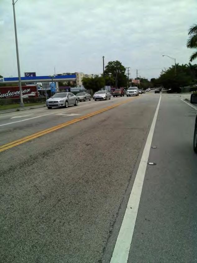
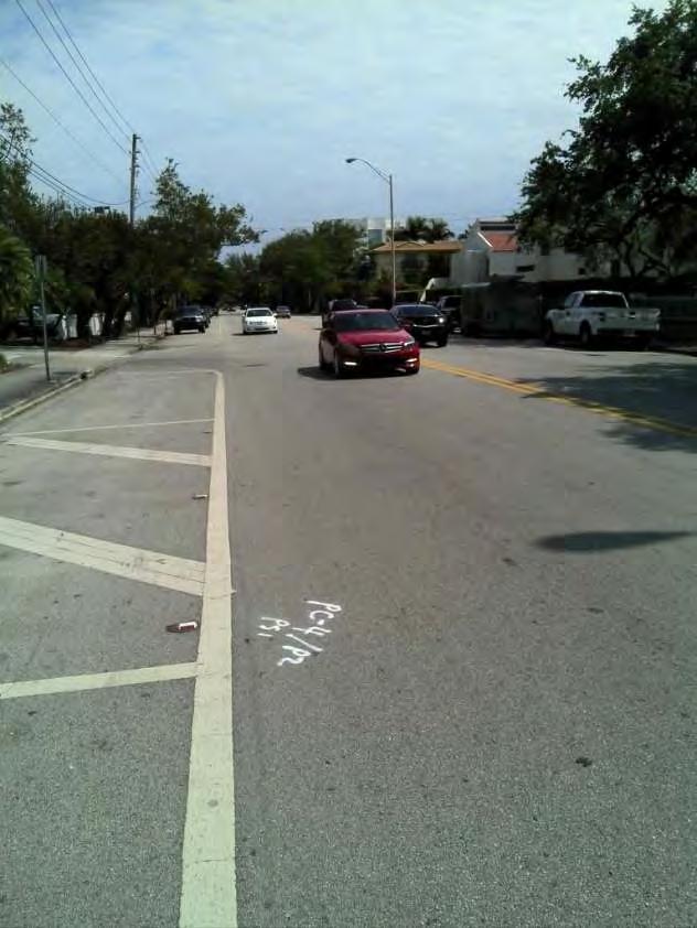
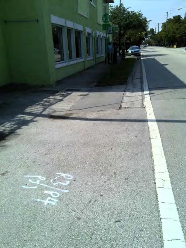


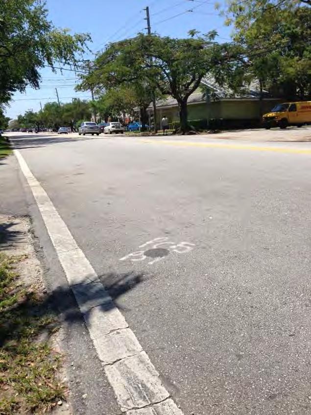
10 SITE PHOTOGRAPHS GEOTECHNICAL ENGINEERING SERVICES DATE: 4/26/213 DRAWN: JC SHEET No.: 2 PSI PROJECT No.: CHKD:: CD
11 BORING LOCATION PLAN B-1 Approximate Boring Location GEOTECHNICAL ENGINEERING SERVICES DATE: 4/26/213 DRAWN: JC SHEET No.: 3 PSI PROJECT No.: CHKD:: CD
12 BORING LOCATION PLAN B-2 Approximate Boring Location GEOTECHNICAL ENGINEERING SERVICES DATE: 4/26/213 DRAWN: JC SHEET No.: 4 4 PSI PROJECT No.: CHKD:: CD
13 BORING LOCATION PLAN B-3 Approximate Boring Location GEOTECHNICAL ENGINEERING SERVICES DATE: 4/26/213 DRAWN: JC SHEET No.: 4 5 PSI PROJECT No.: CHKD:: CD
14 BORING LOCATION PLAN B-4 Approximate Boring Location GEOTECHNICAL ENGINEERING SERVICES DATE: 4/26/213 DRAWN: JC SHEET No.: 6 PSI PROJECT No.: CHKD:: CD
15 BORING LOCATION PLAN B-5 Approximate Boring Location GEOTECHNICAL ENGINEERING SERVICES DATE: 4/26/213 DRAWN: JC SHEET No.: 7 PSI PROJECT No.: CHKD:: CD
16 BORING LOCATION PLAN B-7 B-6 B-8 Approximate Boring Location GEOTECHNICAL ENGINEERING SERVICES DATE: 4/26/213 DRAWN: JC SHEET No.: 8 PSI PROJECT No.: CHKD:: CD
17 BORING LOCATION PLAN B-9 B-11 B-1 Approximate Boring Location GEOTECHNICAL ENGINEERING SERVICES DATE: 4/26/213 DRAWN: JC SHEET No.: 9 PSI PROJECT No.: CHKD:: CD

18 PAVEMENT CORE AND SITE PHOTOGRAPHS CORE LENGTH B-1: 1 GEOTECHNICAL ENGINEERING SERVICES DATE: 4/26/213 DRAWN: JC SHEET No.: 1 PSI PROJECT No.: CHKD:: CD

19 PAVEMENT CORE AND SITE PHOTOGRAPHS CORE LENGTH B-2: 2 5/8 GEOTECHNICAL ENGINEERING SERVICES DATE: 4/26/213 DRAWN: JC SHEET No.: 11 PSI PROJECT No.: CHKD:: CD

20 PAVEMENT CORE AND SITE PHOTOGRAPHS CORE LENGTH B-3: 4 3/8 GEOTECHNICAL ENGINEERING SERVICES DATE: 4/26/213 DRAWN: JC SHEET No.: 12 PSI PROJECT No.: CHKD:: CD


21 PAVEMENT CORE AND SITE PHOTOGRAPHS CORE LENGTH B-4: 1 3/4 GEOTECHNICAL ENGINEERING SERVICES DATE: 4/26/213 DRAWN: JC SHEET No.: 13 PSI PROJECT No.: CHKD:: CD

22 PAVEMENT CORE AND SITE PHOTOGRAPHS CORE LENGTH B-5: 6 3/4 GEOTECHNICAL ENGINEERING SERVICES DATE: 4/26/213 DRAWN: JC SHEET No.: 14 PSI PROJECT No.: CHKD:: CD


23 PAVEMENT CORE AND SITE PHOTOGRAPHS CORE LENGTH B-6: 2 1/2 GEOTECHNICAL ENGINEERING SERVICES DATE: 4/26/213 DRAWN: JC SHEET No.: 15 PSI PROJECT No.: CHKD:: CD
24 PSI Job No.: Project: Location: Elevation (feet) Depth, (feet) Professional Service Industries, Inc. 795 N.W. 64th Street Miami, FL Telephone: (35) Fax: (35) Graphic Log Sample Type Sample No. 1 Recovery (inches) Station: N/A Offset: N/A MATERIAL DESCRIPTION Asphalt Light Brown/Gray LIMEROCK with Fine Sand Light Brown/Gray Fine SAND Drilling Method: SPT Sampling Method: SS Hammer Type: Automatic Boring Location: Refer to Sheet 3 USCS Classification GP SP SPT Blows per 6-inch (SS) N=13 LOG OF BORING B-1 Moisture, % STRENGTH, tsf 2. Sheet 1 of 1 WATER LEVELS While Drilling Upon Completion Delay STANDARD PENETRATION TEST DATA N in blows/ft PL Moisture LL 25 5 Qu Qp 4. N.E. feet N.E. feet Additional Remarks N/A Completion Depth: 2.1 ft Sample Types: Shelby Tube Date Boring Started: 3/12/13 Auger Cutting Hand Auger Date Boring Completed: 3/12/13 Split-Spoon Calif. Sampler Logged By: P.W. Drilling Contractor: PSI, Inc. Rock Core Texas Cone The stratification lines represent approximate boundaries. The transition may be gradual. Latitude: Longitude: Drill Rig: CME 55 Remarks:
25 PSI Job No.: Project: Location: Elevation (feet) Depth, (feet) Graphic Log Sample Type Professional Service Industries, Inc. 795 N.W. 64th Street Miami, FL Telephone: (35) Fax: (35) Sample No. Recovery (inches) Station: N/A Offset: N/A MATERIAL DESCRIPTION Asphalt Light Brown/Gray LIMEROCK with Fine Sand Drilling Method: SPT Sampling Method: SS Hammer Type: Automatic Boring Location: Refer to Sheet 4 USCS Classification SPT Blows per 6-inch (SS) LOG OF BORING B-2 Moisture, % STRENGTH, tsf 2. Sheet 1 of 1 WATER LEVELS While Drilling Upon Completion Delay STANDARD PENETRATION TEST DATA N in blows/ft PL Moisture LL 25 5 Qu Qp feet 8.8 feet Additional Remarks N/A 1 GP N=17 Light Brown/Gray LIMESTONE with Fine Sand N= N= N= N= Percolation Test Performed at a Depth of 15 feet Below Surface Level N=26 Completion Depth: 15.3 ft Sample Types: Shelby Tube Date Boring Started: 4/23/13 Auger Cutting Hand Auger Date Boring Completed: 4/23/13 Split-Spoon Calif. Sampler Logged By: P.W. Drilling Contractor: PSI, Inc. Rock Core Texas Cone The stratification lines represent approximate boundaries. The transition may be gradual. Latitude: Longitude: Drill Rig: CME 75 Remarks:
26 PSI Job No.: Project: Location: Elevation (feet) Depth, (feet) Professional Service Industries, Inc. 795 N.W. 64th Street Miami, FL Telephone: (35) Fax: (35) Graphic Log Sample Type Sample No. Recovery (inches) Station: N/A Offset: N/A MATERIAL DESCRIPTION Asphalt Light Brown/Gray LIMEROCK with Fine Sand Drilling Method: SPT Sampling Method: SS Hammer Type: Automatic Boring Location: Refer to Sheet 5 USCS Classification SPT Blows per 6-inch (SS) LOG OF BORING B-3 Moisture, % STRENGTH, tsf 2. Sheet 1 of 1 WATER LEVELS While Drilling Upon Completion Delay STANDARD PENETRATION TEST DATA N in blows/ft PL Moisture LL 25 5 Qu Qp 4. N.E. feet N.E. feet Additional Remarks N/A 1 GP N=23 Completion Depth: 2.3 ft Sample Types: Shelby Tube Date Boring Started: 3/12/13 Auger Cutting Hand Auger Date Boring Completed: 3/12/13 Split-Spoon Calif. Sampler Logged By: P.W. Drilling Contractor: PSI, Inc. Rock Core Texas Cone The stratification lines represent approximate boundaries. The transition may be gradual. Latitude: Longitude: Drill Rig: CME 55 Remarks:
27 PSI Job No.: Project: Location: Elevation (feet) Depth, (feet) Graphic Log Sample Type Professional Service Industries, Inc. 795 N.W. 64th Street Miami, FL Telephone: (35) Fax: (35) Sample No. Recovery (inches) Station: N/A Offset: N/A MATERIAL DESCRIPTION Asphalt Light Brown/Gray LIMEROCK with Fine Sand Drilling Method: SPT Sampling Method: SS Hammer Type: Automatic Boring Location: Refer to Sheet 6 USCS Classification SPT Blows per 6-inch (SS) LOG OF BORING B-4 Moisture, % STRENGTH, tsf 2. Sheet 1 of 1 WATER LEVELS While Drilling Upon Completion Delay STANDARD PENETRATION TEST DATA N in blows/ft PL Moisture LL 25 5 Qu Qp feet 8.7 feet Additional Remarks N/A 1 GP N=19 Light Brown/Gray LIMESTONE with Fine Sand N= N= N= N= Percolation Test Performed at a Depth of 15 feet Below Surface Level N=23 Completion Depth: 15.2 ft Sample Types: Shelby Tube Date Boring Started: 4/23/13 Auger Cutting Hand Auger Date Boring Completed: 4/23/13 Split-Spoon Calif. Sampler Logged By: P.W. Drilling Contractor: PSI, Inc. Rock Core Texas Cone The stratification lines represent approximate boundaries. The transition may be gradual. Latitude: Longitude: Drill Rig: CME 75 Remarks:
28 PSI Job No.: Project: Location: Elevation (feet) Depth, (feet) Professional Service Industries, Inc. 795 N.W. 64th Street Miami, FL Telephone: (35) Fax: (35) Graphic Log Sample Type Sample No. Recovery (inches) Station: N/A Offset: N/A Asphalt MATERIAL DESCRIPTION Light Brown/Gray LIMEROCK with Fine Sand Drilling Method: SPT Sampling Method: SS Hammer Type: Automatic Boring Location: Refer to Sheet 7 USCS Classification SPT Blows per 6-inch (SS) LOG OF BORING B-5 Moisture, % STRENGTH, tsf 2. Sheet 1 of 1 WATER LEVELS While Drilling Upon Completion Delay STANDARD PENETRATION TEST DATA N in blows/ft PL Moisture LL 25 5 Qu Qp 4. N.E. feet N.E. feet Additional Remarks N/A 1 GP N=19 Completion Depth: 2.6 ft Sample Types: Shelby Tube Date Boring Started: 3/12/13 Auger Cutting Hand Auger Date Boring Completed: 3/12/13 Split-Spoon Calif. Sampler Logged By: P.W. Drilling Contractor: PSI, Inc. Rock Core Texas Cone The stratification lines represent approximate boundaries. The transition may be gradual. Latitude: Longitude: Drill Rig: CME 55 Remarks:
29 PSI Job No.: Project: Location: Elevation (feet) Depth, (feet) Professional Service Industries, Inc. 795 N.W. 64th Street Miami, FL Telephone: (35) Fax: (35) Graphic Log Sample Type Sample No. Recovery (inches) Station: N/A Offset: N/A MATERIAL DESCRIPTION Asphalt Light Brown/Gray LIMEROCK with Fine Sand Drilling Method: SPT Sampling Method: SS Hammer Type: Automatic Boring Location: Refer to Sheet 8 USCS Classification SPT Blows per 6-inch (SS) LOG OF BORING B-6 Moisture, % STRENGTH, tsf 2. Sheet 1 of 1 WATER LEVELS While Drilling Upon Completion Delay STANDARD PENETRATION TEST DATA N in blows/ft PL Moisture LL 25 5 Qu Qp 4. N.E. feet N.E. feet Additional Remarks N/A 1 GP N=32 Light Brown/Gray LIMESTONE with Fine Sand N= N=26 Completion Depth: 6.3 ft Sample Types: Shelby Tube Date Boring Started: 4/23/13 Auger Cutting Hand Auger Date Boring Completed: 4/23/13 Split-Spoon Calif. Sampler Logged By: P.W. Drilling Contractor: PSI, Inc. Rock Core Texas Cone The stratification lines represent approximate boundaries. The transition may be gradual. Latitude: Longitude: Drill Rig: CME 75 Remarks:
30 PSI Job No.: Project: Location: Elevation (feet) Depth, (feet) Graphic Log Sample Type Professional Service Industries, Inc. 795 N.W. 64th Street Miami, FL Telephone: (35) Fax: (35) Sample No. Recovery (inches) Station: N/A Offset: N/A MATERIAL DESCRIPTION Asphalt Light Brown/Gray LIMEROCK with Fine Sand Drilling Method: SPT Sampling Method: SS Hammer Type: Automatic Boring Location: Refer to Sheet 8 USCS Classification SPT Blows per 6-inch (SS) LOG OF BORING B-7 Moisture, % STRENGTH, tsf 2. Sheet 1 of 1 WATER LEVELS While Drilling Upon Completion Delay STANDARD PENETRATION TEST DATA N in blows/ft PL Moisture LL 25 5 Qu Qp feet 8.7 feet Additional Remarks N/A 1 GP N=31 Light Brown/Gray LIMESTONE with Fine Sand N= N= N= N= Percolation Test Performed at a Depth of 15 feet Below Surface Level N=26 Completion Depth: 15.2 ft Sample Types: Shelby Tube Date Boring Started: 4/24/13 Auger Cutting Hand Auger Date Boring Completed: 4/24/13 Split-Spoon Calif. Sampler Logged By: P.W. Drilling Contractor: PSI, Inc. Rock Core Texas Cone The stratification lines represent approximate boundaries. The transition may be gradual. Latitude: Longitude: Drill Rig: CME 75 Remarks:
31 PSI Job No.: Project: Location: Elevation (feet) Depth, (feet) Graphic Log Sample Type Professional Service Industries, Inc. 795 N.W. 64th Street Miami, FL Telephone: (35) Fax: (35) Sample No. Recovery (inches) Station: N/A Offset: N/A MATERIAL DESCRIPTION Asphalt Light Brown/Gray LIMEROCK with Fine Sand Drilling Method: SPT Sampling Method: SS Hammer Type: Automatic Boring Location: Refer to Sheet 8 USCS Classification SPT Blows per 6-inch (SS) LOG OF BORING B-8 Moisture, % STRENGTH, tsf 2. Sheet 1 of 1 WATER LEVELS While Drilling Upon Completion Delay STANDARD PENETRATION TEST DATA N in blows/ft PL Moisture LL 25 5 Qu Qp feet 7.8 feet Additional Remarks N/A 1 GP N=41 Light Brown/Gray LIMESTONE with Fine Sand N=66 >> N= N= N= Percolation Test Performed at a Depth of 15 feet Below Surface Level N=25 Completion Depth: 15.3 ft Sample Types: Shelby Tube Date Boring Started: 4/23/13 Auger Cutting Hand Auger Date Boring Completed: 4/23/13 Split-Spoon Calif. Sampler Logged By: P.W. Drilling Contractor: PSI, Inc. Rock Core Texas Cone The stratification lines represent approximate boundaries. The transition may be gradual. Latitude: Longitude: Drill Rig: CME 75 Remarks:
32 PSI Job No.: Project: Location: Elevation (feet) Depth, (feet) Professional Service Industries, Inc. 795 N.W. 64th Street Miami, FL Telephone: (35) Fax: (35) Graphic Log Sample Type Sample No. Recovery (inches) Station: N/A Offset: N/A MATERIAL DESCRIPTION Asphalt Light Brown/Gray LIMEROCK with Fine Sand Drilling Method: SPT Sampling Method: SS Hammer Type: Automatic Boring Location: Refer to Sheet 9 USCS Classification SPT Blows per 6-inch (SS) LOG OF BORING B-9 Moisture, % STRENGTH, tsf 2. Sheet 1 of 1 WATER LEVELS While Drilling Upon Completion Delay STANDARD PENETRATION TEST DATA N in blows/ft PL Moisture LL 25 5 Qu Qp 4. N.E. feet N.E. feet Additional Remarks N/A 1 GP N=35 Light Brown/Gray LIMESTONE with Fine Sand N= N=21 Completion Depth: 6.2 ft Sample Types: Shelby Tube Date Boring Started: 4/24/13 Auger Cutting Hand Auger Date Boring Completed: 4/24/13 Split-Spoon Calif. Sampler Logged By: P.W. Drilling Contractor: PSI, Inc. Rock Core Texas Cone The stratification lines represent approximate boundaries. The transition may be gradual. Latitude: Longitude: Drill Rig: CME 75 Remarks:
33 PSI Job No.: Project: Location: Elevation (feet) Depth, (feet) Professional Service Industries, Inc. 795 N.W. 64th Street Miami, FL Telephone: (35) Fax: (35) Graphic Log Sample Type Sample No. Recovery (inches) Station: N/A Offset: N/A MATERIAL DESCRIPTION Asphalt Light Brown/Gray LIMEROCK with Fine Sand Drilling Method: SPT Sampling Method: SS Hammer Type: Automatic Boring Location: Refer to Sheet 9 USCS Classification SPT Blows per 6-inch (SS) LOG OF BORING B-1 Moisture, % STRENGTH, tsf 2. Sheet 1 of 1 WATER LEVELS While Drilling Upon Completion Delay STANDARD PENETRATION TEST DATA N in blows/ft PL Moisture LL 25 5 Qu Qp 4. N.E. feet N.E. feet Additional Remarks N/A 1 GP N=12 Light Brown/Gray LIMESTONE with Fine Sand N= N=3 Completion Depth: 6.2 ft Sample Types: Shelby Tube Date Boring Started: 4/23/13 Auger Cutting Hand Auger Date Boring Completed: 4/23/13 Split-Spoon Calif. Sampler Logged By: P.W. Drilling Contractor: PSI, Inc. Rock Core Texas Cone The stratification lines represent approximate boundaries. The transition may be gradual. Latitude: Longitude: Drill Rig: CME 75 Remarks:
34 PSI Job No.: Project: Location: Elevation (feet) Depth, (feet) Professional Service Industries, Inc. 795 N.W. 64th Street Miami, FL Telephone: (35) Fax: (35) Graphic Log Sample Type Sample No. Recovery (inches) Station: N/A Offset: N/A MATERIAL DESCRIPTION Asphalt Light Brown/Gray LIMEROCK with Fine Sand Drilling Method: SPT Sampling Method: SS Hammer Type: Automatic Boring Location: Refer to Sheet 9 USCS Classification SPT Blows per 6-inch (SS) LOG OF BORING B-11 Moisture, % STRENGTH, tsf 2. Sheet 1 of 1 WATER LEVELS While Drilling Upon Completion Delay STANDARD PENETRATION TEST DATA N in blows/ft PL Moisture LL 25 5 Qu Qp 4. N.E. feet N.E. feet Additional Remarks N/A 1 GP N=41 Light Brown/Gray LIMESTONE with Fine Sand N= N=25 Completion Depth: 6.2 ft Sample Types: Shelby Tube Date Boring Started: 4/24/13 Auger Cutting Hand Auger Date Boring Completed: 4/24/13 Split-Spoon Calif. Sampler Logged By: P.W. Drilling Contractor: PSI, Inc. Rock Core Texas Cone The stratification lines represent approximate boundaries. The transition may be gradual. Latitude: Longitude: Drill Rig: CME 75 Remarks:
35 TABLE 1 SUMMARY OF TEST LOCATIONS BIRD AVENUE FROM US-1 TO AVIATION AVENUE COCONUT GROVE, FLORIDA PSI PROJECT NO.: BORING NUMBER NORTHING (1) EASTING (1) B B B B B B B B B B B BORING DEPTH (FEET) GROUNDWATER TABLE DEPTH (FEET) (2) N.E. 8.8 N.E. 8.7 N.E. N.E N.E. N.E. N.E. Note: (1) Plane coordinates were obtained by using a hand held GPS instrument (Garmin 6 CSX) with the reported data being accurate to within 1 feet (2) N.E. Groundwater level not encountered
36 TABLE 2 SUMMARY OF PERCOLATION TEST RESULTS BIRD AVENUE FROM US-1 TO AVIATION AVENUE COCONUT GROVE, FLORIDA PSI PROJECT No Test Date Diameter Depth of Depth to Groundwater Level Hydraulic Saturated Hole Average K, Hydraulic No. Performed Casing Perforated PVC Hole Below Ground Surface (Feet) Head, H2 Depth, Ds Flow Rate, Q Conductivity (Inches) (Inches) (Feet) Prior to Test During Test (Feet) (Feet) (gpm) cfs/ft 2 -ft B-2 23-Apr E-4 B-4 23-Apr E-4 B-7 24-Apr E-4 B-8 23-Apr E-4 Note: (1) The above hydraulic conductivity values are for a french drain installed to the same depth as the borehole tests. The values represent an ultimate value. The designer should apply the appropriate factor of safety. (2) The hydraulic conductivity values were calculated based on the South Florida Water Management District's USUAL OPEN HOLE CONSTANT HEAD percolation test procedure as shown on the following page.
37 USUAL OPEN HOLE TEST Q N.G. d HI H2 WATER TABLE DS ELEV. A K= 4Q π d (2H 2 ² + 4H 2 D S + H 2 d) K= HYDRAULIC CONDUCTIVITY (CFS/FT.² - FT.HEAD) Q= STABILIZED FLOW RATE (CFS) d= DIAMETER OF TEST HOLE (FEET) H2 = DEPTH TO WATER TABLE (FEET) DS = SATURATED HOLE DEPTH (FEET) ELEV. A = PROPOSED TRENCH BOTTOM ELEV. HI = AVERAGE HEAD ON UNSATURATED HOLE SURFACE (FT.HEAD)