THE FUTURE OFFSITE CONSTRUCTION & DIGITAL ENGINEERING MATHEW RILEY MANAGING DIRECTOR, RAMBOLL UK
|
|
|
- Erica Alexander
- 5 years ago
- Views:
Transcription

1 THE FUTURE OFFSITE CONSTRUCTION & DIGITAL ENGINEERING MATHEW RILEY MANAGING DIRECTOR, RAMBOLL UK


2 DRIVERS FOR CHANGE
3 PRODUCTIVITY

4 MODERNISE BY CONSTRUCTING OFF SITE Client benefits Enable informed decisions earlier Faster delivery Create better quality in less time De-risk the programme downstream Lower costs

5 MODERNISE THROUGH DIGITALISATION Digitalisation Conceiving tools that speed up the analysis of design to: Increase productivity Improve quality Go further faster

6 COMBINING EXPERTISE IN OFFSITE CONSTRUCTION & SKILLS IN DIGITALISATION

7 OFFSITE CONSTRUCTION & DFMA Design for Manufacture and Assembly (DfMA) Combining design for ease of manufacture and design for ease of assembly in a lean approach Manufacturing done off site in a safer, controlled environment with higher quality control Assembly on site uses fewer site operatives and at a faster speed


8 BENEFITS OF DFMA Higher quality control Increased knowledge transfer Lower financial risk DfMA Accurate coordination Greater material quantity certainty Reduced assembly time
9 It costs too much There is no architectural freedom You can t insure the building It won t last 50 years The connection design is difficult Design is too restrictive It will feel prefab No one knows how to design with it The supply chain is not developed
10 SCANDINAVIAN APPROACH

11 RAMBOLL TIMELINE OF OFFSITE DESIGN

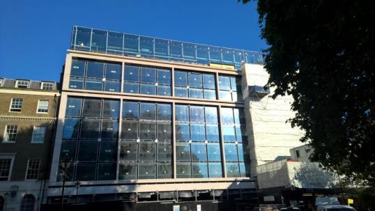
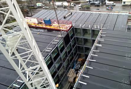
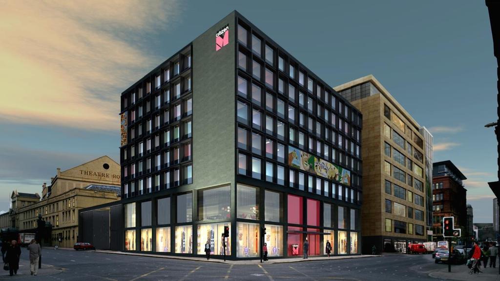
12 CLT - DALSTON LANE


13 CLT - DALSTON LANE


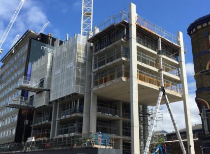
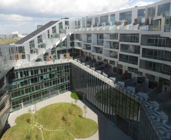
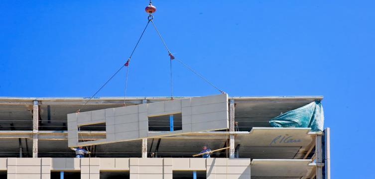
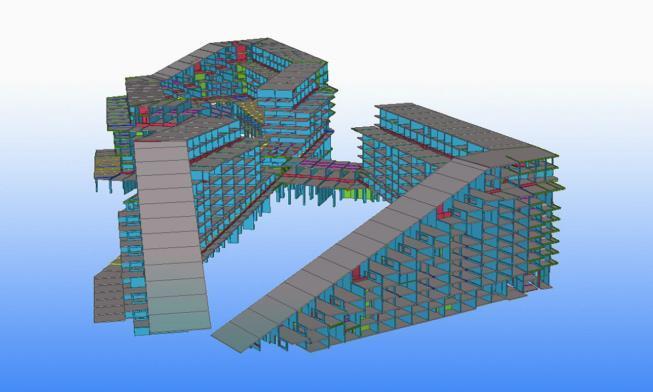
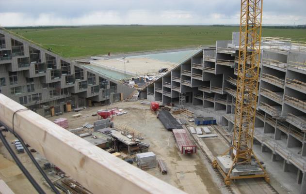
14 PRE-CAST CONCRETE - MERANO

15 MODULAR STEEL
16
17 PROGRAMME SPEED Concrete Insitu CLT Precast Concrete Design Phase On site Phase Modular
18 QUALITY OF FINISHED BUILDING Concrete Insitu CLT Precast Concrete Quality Modular
19 COST EFFICIENCY OF OFFSITE MANUFACTURE Cost Efficiency No. of Storeys
20 OFFSITE AND DIGITALISATION

21 PERCEPTIONS OF PREFABRICATION
22 OPTIONS DEVELOPMENT TRADITIONALLY OPTIONS DEVELOPMENT THROUGH DIGITALISATION
23 DIGITAL TOOLKIT
24 DIGITAL TOOLKIT RAPID OPTIONS APPRAISAL

25 RAPIDLY ITERATING MASSING OPTIONS

26 PARAMETRICALLY ASSESSMENT EXPLORING BUILDING FORM
27 DIGITAL TOOLKIT AUTOMATING LOAD TAKEDOWN

28 LOAD TAKE DOWN PROCESS Tributary Area, A = b d Load per Unit Area, W Total Load on Column =σ A W b d
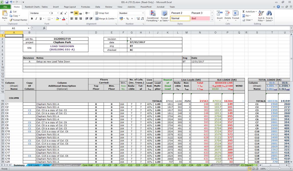
29 SPREADSHEET METHOD


30 LOAD TAKEDOWN TOOL PROTOTYPE FAST TURNAROUND EASY USE EASY REVIEW

31 TADPOLE TRADITIONAL 15 hrs AUTOMATED AUTOMATED hr 2 hr FAST TURNAROUND EASY USE EASY REVIEW


32 MANUAL EDITING TOOLS FAST TURNAROUND EASY USE EASY REVIEW

33 RESIDENTIAL BUILDING DASHBOARD FAST TURNAROUND EASY USE EASY REVIEW

34 MAJOR RESIDENTIAL REGENERATION PROJECT
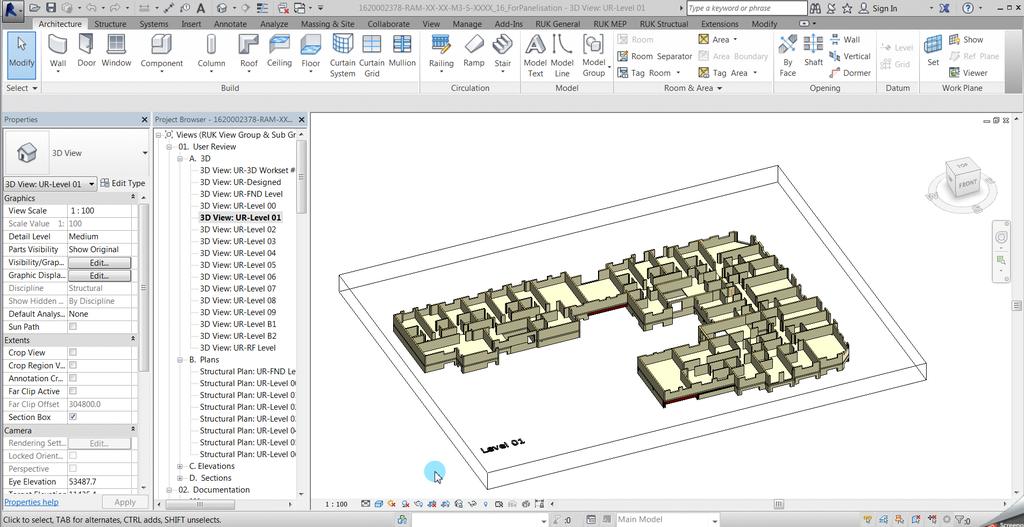
35 TYPICAL DESIGN PROCESS Stability Modelling (15 hours + 2 hours review) Core Design Input Architectural plan / model 52 CORES 2,340 hrs Load Takedown (15 hours + 2 hours review) 4 People = 4 Months Foundation Design Column Design Output BIM model/ Drawings Slab Modelling (15 hours + 2 hours review) Slab Design
36 OUR SOLUTION Stability Modelling (15 hours + 2 hours review) Core Design Input Architectural plan / model Load Takedown (15 hours + 2 hours review) Foundation Design Output BIM model/ Drawings Column Design Slab Modelling (15 hours + 2 hours review) Slab Design


37 OUR DRIVERS FAST TURNAROUND GRASSHOPPER PROTOTYPE EASY USE STAND ALONE TOOLS EASY REVIEW DASHBOARD
38 VALUE ADDED TO PROJECT X 52 CORES TRADITIONAL 2,340 hrs AUTOMATED 208 hrs TOOL DEVELOPMENT 150 hrs 52 CORES 2,340 hrs 4 People = 4 Months 52 CORES 208 hrs 4 People = 1.5 Weeks POTENTIAL 12X FASTER
39 NEW OPPORTUNITIES Merge Cobra into Tadpole Develop robust robot interface Architect DXF Cobra Robot Revit models Grasshopper Tadpole Develop input options Power BI Revit Automated Design Documentation Detailed Design Calculation Customised outputs Develop active dashboard link Client Cost Consultant Work with clients / cost consultants to develop combined DFMA dashboards PRESENTATION


40 NEW OPPORTUNITIES Merge Cobra into Tadpole Develop robust robot interface Architect DXF Cobra Robot Revit models Grasshopper Tadpole Develop input options Optimisation loop Power BI Revit Automated Design Documentation Detailed Design Calculation Customised outputs Develop active dashboard link Client Cost Consultant Work with clients / cost consultants to develop combined DFMA dashboards PRESENTATION
41 DIGITAL TOOLKIT RAPID CORE DESIGN

![STRUCTURAL DESIGN [2]](/docs-images/85/92578161/images/42-1.jpg "PANELISATION [3]")
42 CROSS LAMINATED TIMBER BUILDING [1] STRUCTURAL DESIGN [2] PANELISATION [3] FABRICATION
43 TOOL WORK FLOW [1] INITIAL DESIGN [2] CUTTING LINE GENERATION [3] PANELISATION INFORMATION

![PANEL [2]](/docs-images/85/92578161/images/44-1.jpg "CUTTING")

44 PANELISATION [1] INITIAL PANEL [2] CUTTING LINES GENERATION [3] PANELISATION
45

46 VALUE POTENTIAL 3 RD PARTY PANELISATION ~ hours MANUAL PANELISATION ~ hours 50% Time Saving AUTOMATED PANELISATION ~60-80 hours 90% Time Saving

47 AUTOMATING BIM POINT CLOUDS TO 3D OBJECTS


48 WHAT IS A POINT CLOUD? Millions or even billions of individual XYZ coordinates So dense they often appear solid Commonly captured by laser scanning Based on the time-of-flight of a laser beam hitting target and returning to sensor


49 PROCESS Point cloud Edgewise processing Revit model

50 AUTOMATED (1 CLICK) MODELLING 1 click pipe model 1 click operation finds 50-75% of the walls and pipes Easy to use tools to clean up and finish model Time savings of at least 50% over manual modelling Improved accuracy and QA After clean up

51 ASSISTED MODELLING For structure, user guides process by selecting type of structural element and region of points Time savings of at least 25% over manual modelling Improved accuracy and QA Particularly effective for non-horizontal or vertical members

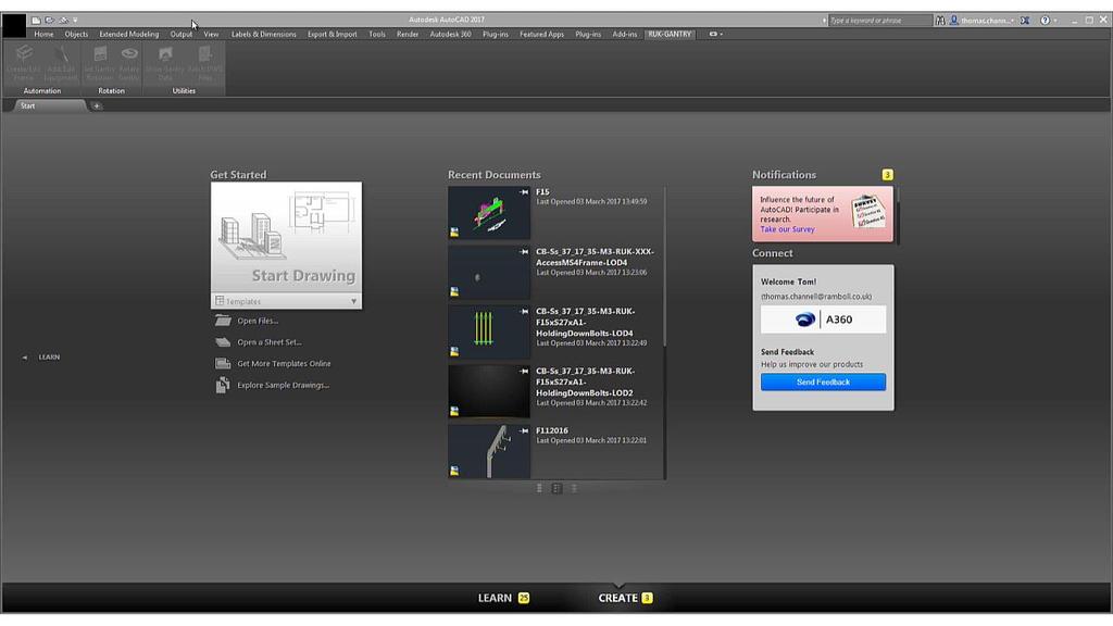
52 AUTOMATING GANTRY DESIGN Optimisation approach based on known Parameters Gantry Name Member Sizes Leg Spacing Maximums Profiles Bay Spacing Gantry Type Boom Spacing Length Minimums
 PLACEMENT OF GANTRY MODEL IN REAL WORLD")
53 AUTOMATING GANTRY DESIGN 3D MODELS FRAME (8 TYPES) EQUIPMENT (MULTIPLE VARIABLES) PLACEMENT OF GANTRY MODEL IN REAL WORLD COORDINATES
54
55 BENCHMARKING 60.0m C07 N-S 50.0m 40.0m C02 NW-SE Building Height (m) 30.0m C08 N-S D01 NW-SE 20.0m 10.0m 0.0m 0.0m³ 1.0m³ 2.0m³ 3.0m³ 4.0m³ 5.0m³ 6.0m³ 7.0m³ 8.0m³ 9.0m³ 10.0m³ Moment of Inertia (m 4 ) / Building Width (m)


56 NEXT STEPS: STRUCTURES DATABASE DATA COLLECTION DESIGNS KNOWLEDGE BENCHMARKING
57 EVOLUTION OF DESIGN
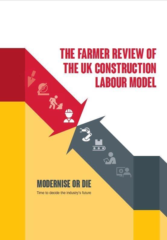
58 MODERNISE OR DIE Project Controls: Are you in control? What are you in control of? Automation of Controls New benchmarks Business Case: Unlocking Productivity Changing Business Model Knowledge and Innovation Time compression vs. Linear process Procurement!

59 THANK YOU 59