Boundaries and Barriers
|
|
|
- Alan Chapman
- 5 years ago
- Views:
Transcription


1 Overview of Presentation Boundaries and Barriers High Performance Enclosures Dr John F. Straube Dupont Young Professor School of Architecture & Dept of Civil Engineering University of Waterloo Ontario, Canada Role of various layers Structure Rain Heat Air High Performance Enclosures Enclosure Design Principles-1 Enclosure Requirements Support Control Heat This talk Air Rain Vapor Fire Sound Finish Design a complete load transfer path structure, windows, ties, etc All loads go to ground or it fails Respect the site and climate rain, sun, wind, hill, valley, high rise or low-rise Continuous rain control plane control with surface features and detailing Drained, storage, or perfect barrier strategy Continuous plane of air barrier tightness fastidious attention to detail 3-D


 Use")


2 Enclosure Design Principles-2 Provide a continuous plane of insulation ideally separate structure from enclosure Avoid thermal bridges Provide a moisture tolerant design balance wetting, drying, and storage (matl s, climate) Use appropriate levels of vapour control vapour barriers are not the answer Accommodate movements and tolerances Practise: Continuous Layers 1. Structure connect all parts together to foundation 2. Continuous Rain Control Drainage plane, gap and flashing is needed 3. Continuous Insulation Exterior insulation layer to slow heat flow, blunt cold spots (R>5) 4. Air barrier Continuous air barrier to control air flow Vapor retarder less important, may have holes The Enclosure: Adding the Layers Structure Air Barrier Insulation Rain Control Finish
 2 7 6 5 4 Cladding Cavity Insulation Air barrier & Water resistant")
 Typical Materials/Sub-systems Masonry - brick or block 1 Steel Stud and Drywall (shown) Wood Stud and Drywall Concrete")

 Steel Stud")

 2 Cladding 7 Cavity insulation 6 Air barrier 5 Water resistant barrier & Drainage gap shelf angle Typical Materials/Sub-systems Masonry -")
 Stucco / EIFS Compromise wall Houses Rain Heat Air 6 Exterior sheathing 7 Rigid Fibrous Interior sheathing or sheet Expanded")
 Cellulose Spray Foam Paint or vinyl wallpaper on drywall Polyethylene foil-backed drywall Kraft facing")
3 sealant 1 Load-bearing inner wythe Steel tie back connection 2 Cladding 3 Studspace insulation 4 Vapour barrier (opt) Water resistant barrier & 5 drainage gap 6 Air barrier Loadbearing 1 inner wythe Interior Finish (opt) Cladding Cavity Insulation Air barrier & Water resistant barrier vapour barrier (opt) Drainage gap Sealant/gasket & drained joint (rainscreen) fire and smoke stop (opt) deflection space (unless load bearing inner wythe) Typical Materials/Sub-systems Masonry - brick or block 1 Steel Stud and Drywall (shown) Wood Stud and Drywall Concrete Masonry or Siding 2 Stucco or DEFS Panels (metal, stone, ceramic, etc) Precast concrete (shown) Batt (in studspace) 3 Cellulose Spray Foam Paint or vinyl wallpaper on drywall 4 Polyethylene foil-backed drywall Kraft facing on batt Spray-foam 5 Trowel- / spray- applied membrane Sheet membrane 6 Exterior sheathing Interior sheathing or sheet Spray-foam Trowel- / spray- applied membrane Sheet membrane Poor wall Primary building structure deflection space or structural connection as per structural intent Typical Materials/Sub-systems Masonry (shown) Steel Stud (uninsulated) Wood Stud (uninsulated) Concrete Masonry (shown) Siding Panels (steel, stone, etc) Precast Stucco or EIFS Rigid Fibrous (shown) Expanded Polystyrene Extruded Polystyrene Polyurethane Products Wood Fibreboard Polyisocyanurate Sheet membrane 4 Trowel- and spray-applied 5 Spray foam Smart wall Load bearing 1 inner wythe Studspace 3 insulation Vapour 4 barrier (opt) sealant deflection space (unless load bearing inner wythe) 2 Cladding 7 Cavity insulation 6 Air barrier 5 Water resistant barrier & Drainage gap shelf angle Typical Materials/Sub-systems Masonry - brick or block 1 Steel Stud and Drywall (shown) Wood Stud and Drywall Concrete Masonry 2 Siding Panels (metal, stone, ceramic, etc) Precast concrete (shown) Stucco / EIFS Compromise wall Houses Rain Heat Air 6 Exterior sheathing 7 Rigid Fibrous Interior sheathing or sheet Expanded Polystyrene Spray-foam Extruded Polystyrene Trowel- / spray- applied Polyurethane Products membrane Wood Fibreboard Sheet membrane Polyisocyanurate Batt (in studspace) Cellulose Spray Foam Paint or vinyl wallpaper on drywall Polyethylene foil-backed drywall Kraft facing on batt Spray-foam Trowel- / spray- applied membrane Sheet membrane


 Single top plate Point load transferred between studs by rim closure material acting as header.")
4 Roof framing/trusses line up with wall and floor framing 1. Structure Advanced Framing System No headers in non-bearing wall Single top plate Use resources efficiently to provide a safe structure Connect roof to wall, windows and doors to wall, wall to floors and foundation, foundation to earth Stack Framing Lintels where needed See Lstiburek s stuff buildingscience.com Single stud at rough opening No cripples under window opening Two stud corners Insulated header Header hangers instead of jack studs (see Figure 5.5) Single top plate Point load transferred between studs by rim closure material acting as header. If rim closure material is nonstructural, support will be required under point loads. Use solid blocking between joists. Avoid waste

5 Load Transfers 2. Continuous Rain Control Deflection Drainage Drying First reduce rain on building with details Stop rain penetration by Drainage (or Storage or Perfect Barrier) Drainage plane continuous Drainage gap continuous Lead to flashing and weep holes J. Lstiburek Deflection


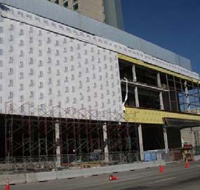
6 No drainage plane Is there a gap? Drainage Airspace often blocked Water can bridge over Draining surface(s) vs drainage layer Drainage plane Must be a capillary break Must be durable when wetted Must be lapped or continuous Peel and stick, BP, Tyvek, spray applied Must lead to flashing (waterproof or steep slope) and weep holes Types Format Sprayed on trowel applied Sheet applied Desirable Attributes Self sealing Fully adhered Vapor permeable Housewrap Problems: materials& installation
")
 for pressure moderation (>1/4 ) Finger Space (buildability) Adjustment and tolerances Ventilation Often useful Water drains")
7 Self Sealing Role of the Gap / Airspace Self sealing used in critical locations on houses or commercial buildings Needed to reduce the flow of even small amounts of water All existing products are vapor impermeable this is a problem Capillary break (>1/16 ) Drainage space (>1/16 ) No hydrostatic pressure Air Chamber for ventilation drying (>1/2?) for pressure moderation (>1/4 ) Finger Space (buildability) Adjustment and tolerances Ventilation Often useful Water drains astonishingly well between sheets of building paper
8 Moisture Content (%) Ventilation Drying Field Results: ASHRAE RP Induced wetting event 5 Vinyl w/#15 Felt Vinyl w/tyvek 0 1-May 8-May 15-May 22-May 29-May 5-Jun 12-Jun Brick w/tyvek & non-ventilated vented Brick w/tyvek Brick w/tyvek ventilated Brick w/#15 felt Felt ventilated Light cladding systems drainage space sheathing membrane insulation Can perform well Cladding leaks a lot Battens ensures drainage occurs and provides ventilation drying Flashing very important sheathing strapping wood siding or vinyl siding Flashing: Details Eavestrough Drainage Space Sloped Flashing Sub Sill Flashing Sloped Grade 5% min 3. Continuous Insulation Protect the structure and interior with a continuous blanket of insulation Aim for min. R5 everywhere Keeps structure warm = dry! Avoids interstitial condensation Accelerates drying Covers thermal bridges True R-value


9 Thermal Bridging Heat flows more easily through studs Wood R6 vs R20. Steel R0.4 vs R20 What about double, triple studs, rim joists? Thermal Bridging Major losses thru steel Result: heat loss moisture problems Thermal Bridging: Common Problems Thermal Bridging Solution Insulated sheathing Even 1 is big deal


10 All on the exterior Windows are thermal bridges Most windows are R2, good windows are R3 Curtainwalls rarely over R3 These are thermal bridges! Need to try for R4 or 5! 4. Air Barrier Provide a continuous barrier to air flow over the whole building
11 Air Barriers vs Vapor Barriers Vapour Barriers Control Vapour Diffusion Why? 1. Moisture wetting and drying Air Barriers Control Air Leakage Why? Six reasons. Heat (for 1. comfort & 2. energy considerations) 3. Moisture 4. Sound 5. Smoke & 6. odours and dust Air barriers Stop the flow of air Equals Stop Moisture (condensation) Drafts Energy Noise Dust Odors and smoke Vapor barriers = drying retarders Vapor diffusion is a slow process Uniform action = small holes don t matter Use as needed, not more Air Barriers are Systems (not materials) Air barrier systems are required to stop airflow through enclosure ABS can be placed anywhere in the enclosure Must be strong enough to take wind gusts Air barrier systems must be continuous They leak at joints, interfaces, penetrations multiple air barrier planes are useful for redundancy


12 Condensation: Cool air contains less vapor Cool air increase RH Heat air decrease RH Air leakage vs Diffusion Air leakage is much more critical Walls sensitive to diffusionrelated condensation will be more sensitive to air leakage Air leakage Diffusion 32 F 50 F John 68 FStraube
13 100% RH 75% RH 50% RH 25% RH 1. Air leakage occurs at higher outdoor temp than diffusion 2. Air leakage results in a much greater rate of condensation Air Leakage Condensation Air Leakage vs Diffusion Diffusion Summer Winter Tem perat ure ( C) Vapour Pressure (Pa) Vapor diffusion control Provide low permeance on the interior in Vermont Not freezer warehouses and arenas!! Low permeance means 0.5 to 3 perms Depends on interior RH, exterior permeance Adding insulating sheathing means you don t need poly Add enough ins. sheathing and nothing Vapor barriers are drying retarders Air Barrier System Requirements Continuous primary need Strong designed for full wind load Durable critical component - repair, replacement Stiff control billowing, pumping Air Impermeable (may be vapour permeable) Airflow Control: Where Stop airflow anywhere Can locate anywhere in enclosure Should be protected if possible Multiple layers are good Important in all climates

 an air and vapour")
14 As for rain, it is all in the details Poly can be (?) an air and vapour barrier


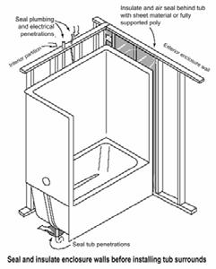
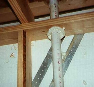
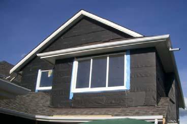
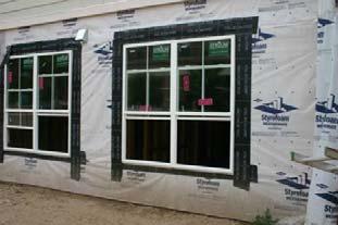
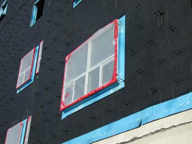
15 Air Sealing Details Air sealing Details Seal ALL penetrations to the outside
 Wall w/o Insulated Sheathing Pressure Profile Air leakage Airflow behind cladding causes cooling or \"wind washing\" of air permeable insulations Suction on sides Cold =")
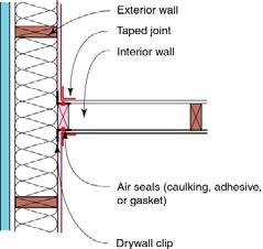
16 Air Sealing Details Airtight electrical boxes in exterior walls and ceilings Convection Barrier (Control Stack Effect) Cold Weather Hot air = light Result: Air Flow Cold air = heavy Control windwashing (lateral flow) Wall w/o Insulated Sheathing Pressure Profile Air leakage Airflow behind cladding causes cooling or "wind washing" of air permeable insulations Suction on sides Cold = Condensation Vapour Diffusion Solution: Add a wind barrier to exterior


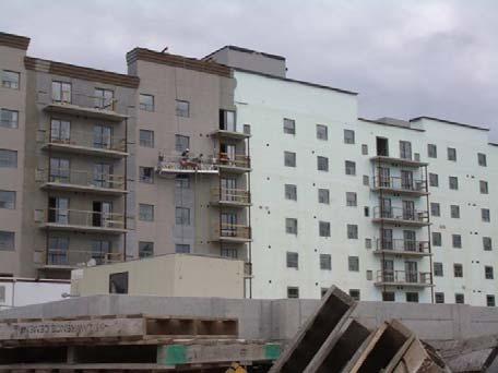
17 Wall with Insulated Sheathing Examples Air leakage Some typical and odd examples Warm = no condensation Vapour Diffusion Rigid or semi-rigid insulation


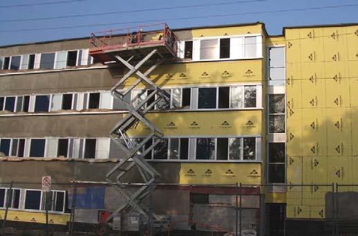
18 Combined air, vapor, drain, insulation ICF concrete is air barrier Drainage planes Trowel applied air and water barrier


19 Combined air and drainage plane SPF air barrier, polyiso drain plane Huber Zip Peel and stick

 Use appropriate levels of vapour control vapour barriers are not the answer Accommodate movements and")
20 You can use good materials in stupid ways to screw things up Enclosure Design Principles-1 Design a complete load transfer path structure, windows, ties, etc All loads go to ground Respect the site and climate rain, sun, wind, hill, valley, high rise or low-rise Continuous rain control plane control with surface features and detailing Drained, storage, or perfect barrier strategy Continuous plane of air barrier tightness fastidious attention to detail 3-D Enclosure Design Principles-2 Provide a continuous plane of insulation ideally separate structure from enclosure Avoid thermal bridges Provide a moisture tolerant design balance wetting, drying, and storage (matl s, climate) Use appropriate levels of vapour control vapour barriers are not the answer Accommodate movements and tolerances


21 Continuous Layers 1. Structure connect all parts together to foundation 2. Continuous Rain Control Drainage plane, gap and flashing is needed 3. Continuous Insulation Exterior insulation layer to slow heat flow, blunt cold spots 4. Air barrier Continuous air barrier to control air flow Vapor retarder less important, may have holes Website University of Waterloo Building Engineering Group Building Science Textbook at
22