Training Objectives Module A
|
|
|
- Alison Harvey
- 5 years ago
- Views:
Transcription
 Significant features and benefits")
1 Engineered Wood Products Simplified Module A Introduction to Engineered Wood Products New England Building Officials Education Associations 50 th Conference October 4, 2016 Robert A. Kuserk, PE Training Objectives Module A Upon completing this training students will be able to identify and describe Various types of engineered wood products (EWP) Significant features and benefits Significant characteristics Appropriate applications (uses) for each 1
2 Training Objectives Review Module B Types of loads on building components Designing for load paths Deflection and calculated spans of I-Joists Simple and Multiple spans Specifying engineered wood products Training Objectives Module C Upon completing this training students will be able to identify and describe Best practices in designing engineered wood floor systems Recommendations for Rim Board in I-joist floor systems Proper techniques for notching and drilling I- joists and Rim Board Correct use of web stiffeners, squash blocks and blocking for I-joist floors 2


3 What Are Engineered Wood Products? Structural Wood Products I-Joists Glulam Glued Laminated Timber SCL Structural Composite Lumber LVL Laminated Veneer Lumber OSL Oriented Strand Lumber LSL Laminated Strand Lumber PSL Parallel Strand Lumber Why Engineered Wood Products? Predictable Performance Consistent dimensions Straight Predictable Less Shrinkage Less Crowning Long Lengths While design values of some lumber product have recently decreased, the design values of engineered wood products have not been effected. 3


4 Why Engineered Wood Products? Engineered design = Greater flexibility Longer lengths and stronger members Why Engineered Wood Products? Engineered design = Environmentally better Longer lengths cut to size to reduce jobsite waste Engineered wood products are a system 4


 Slicing")
5 Manufacturing Engineered Wood Products Engineered Wood Any wood-based building material that has been improved physically by a man-made process. Manufacturing Engineered Wood Products Machined into pieces Sawing (Glulam) Peeling (Plywood/LVL) Slicing (OSB/OSL) 5


6 Manufacturing Engineered Wood Products Processed for maximum strength by: Drying Sorting Grading Aligning Manufacturing Engineered Wood Products Manufactured by Applying Adhesives Pressing Curing Finishing 6


7 Wood as a Building Material Product design takes advantage of the natural properties of wood Has different properties depending on grain orientation. Expands and contracts with changes in moisture content. It is stronger when dried. Naturally occurring characteristics (knots, sloping grain) reduce it s strength. Wood as a Building Material Wood has hollow cells like a bundle of straws Compression parallel to grain wood is relatively strong Compression perpendicular to grain wood is weaker cells more easily crush 7

8 Mechanical Properties of Wood Compression Parallel studs, columns, posts, truss chords Perpendicular deformation of member Tension Parallel Highest strength beams, panels Perpendicular Weakest capacity connections Mechanical Properties of Wood Shrinkage or expansion in wood expected across the grain. Longitudinal shrinkage or expansion is negligible. 8
 Web Typically OSB (sliced, dried, aligned, glued, pressed) Placing wood fiber where the stresses are greatest")
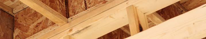
9 Mechanical Properties of Wood Wood I-Joist Anatomy Flange Typically LVL (peeled, dried, aligned, glued, pressed) or MSR lumber (sawn, dried, sorted, graded) Web Typically OSB (sliced, dried, aligned, glued, pressed) Placing wood fiber where the stresses are greatest 9
10 I-Joist Advantages Engineered design = Environmentally better Utilizes the wood fiber where needed for strength minimizing use of wood fiber Wood placed where stresses are greatest 46% less than lumber at 16ꞌꞌ vs. I-joist at 19.2ꞌꞌ 36% less when both are at 16ꞌꞌ Engineered Wood Floors Nearly 50 Percent of Raised Floor Systems Wood Trusses 17% Other 1% Lumber 33% I-joist 49% From Home Innovations Research Labs, 2013 Builder Practices Survey 10


11 Why Engineered Wood Products? Engineered design = Efficient use Lighter and easier to handle and faster to install Why Engineered Floor Systems? Engineered design = Better systems Flatter surfaces, stronger, quieter floors, fewer problems 11


12 More I-Joist Advantages Engineered design = Greater flexibility Web material can be removed for ductwork Wood I-Joist Standard Depths 9-1/2ꞌꞌ 11-7/8ꞌꞌ 14ꞌꞌ 16ꞌꞌ 18 Varied flange widths and depths Structural performance varies per manufacturer 12
 Photo")

13 Laminated Veneer Lumber (LVL) Veneers bonded together Common uses Beams Headers, Rafters Scaffold planking All grain parallel to length Laminated Veneer Lumber (LVL) Photo courtesy of Pacific Woodtech Corporation Standard Depths 9-1/2ꞌꞌ 11-7/8ꞌꞌ 14ꞌꞌ 16ꞌꞌ 18ꞌꞌ Common thicknesses 1-1/2ꞌꞌ 1-3/4ꞌꞌ 3-1/2ꞌꞌ 5-1/4ꞌꞌ 7ꞌꞌ Common stiffness ratings : 1.5E, 1.8E, 2.0E 13

14 Parallel Strand Lumber (PSL) Manufactured from veneers clipped into long strands in a parallel formation and bonded together Strand length-to-thickness ratio is around 300 Common uses: headers, beams, load-bearing columns Specs are published on a proprietary basis by the manufacturer and recognized in evaluation reports. Parallel Strand Lumber (PSL) Standard Depths 9-1/2ꞌꞌ 11-7/8ꞌꞌ 14ꞌꞌ 16ꞌꞌ 18ꞌꞌ Common thicknesses 3-1/2ꞌꞌ 5-1/4ꞌꞌ 7ꞌꞌ Common stiffness ratings: 2.0E 14


15 Other Structural Composite Lumber Laminated Strand Lumber (LSL) Flaked strand length-to-thickness ratio is around 150 Common uses: studs columns and headers Oriented Strand Lumber (OSL) Flaked strand length-to-thickness ratio is around 75 Common uses: studs Other Structural Composite Lumber Standard Depths 7-1/4ꞌꞌ 9-1/2ꞌꞌ 11-7/8ꞌꞌ 14ꞌꞌ 16ꞌꞌ Common thicknesses 1-1/2ꞌꞌ 1-3/4ꞌꞌ 3-1/2ꞌꞌ Common stiffness ratings: 1.35E & 1.55E 15


16 Glued Laminated Timbers (Glulam) Dimension lumber laminations Wood laminations bonded together Wood grain runs parallel to the length Common uses: beams, headers and columns Glued Laminated Timbers (Glulam) Photo courtesy of Anthony Forest Products Standard Depths 9-1/2ꞌꞌ 11-7/8ꞌꞌ 14ꞌꞌ 16ꞌꞌ Common thicknesses 3-1/2ꞌꞌ 5-1/2ꞌꞌ 6-3/4ꞌꞌ Lengths up to 48ꞌ Common stiffness ratings: 1.8E 16


17 Code Recognized Tested for Performance Testing at APA labs Proprietary ES Reports and APA Product Reports APA Product Reports Report indicates that product meets the intention of the listed codes when used as stated and within the specified limitations. Design properties are included. Available for download at 17


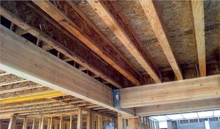
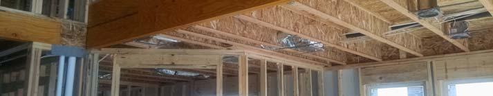
18 Floor Joists Roof Rafters 18

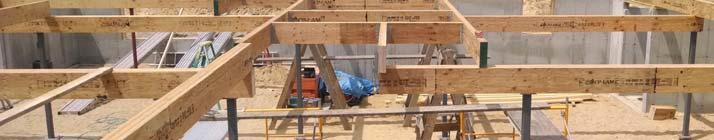
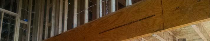
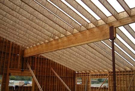
19 LVL Floor Beams LVL Floor Beams 19


20 LVL Headers Photo courtesy of Pacific Woodtech Corporation LVL Garage Door Headers 20


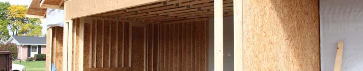
21 LVL Wall Framing Photo courtesy of Boise Cascade Engineered Wood Products LSL Wall Framing Need Photo Photo courtesy of Louisiana Pacific Building Products 21


22 LSL Headers PSL Wall Framing Tall wall applications Headers Beams Columns Photo courtesy of Weyerhaeuser Corporation 22

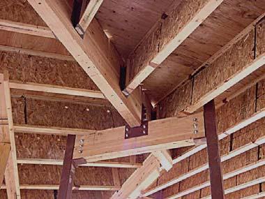
23 PSL Beam Glulam Beam 23

24 Glulam Wall Framing Engineered Wood: A Green Choice Manufacturing of engineered wood products is resource efficient and energy efficient Manufacturing techniques have evolved to maximize use of fiber and energy Industrial output per unit of wood input increased 40% in the last 50 years Over one-half of the energy consumed in manufacturing wood products is bioenergy. U.S. wood products industry accounts for 60% of bioenergy production and use. 24

25 Why Engineered Wood Products? Predictable performance Uniform weight and strength Systems are quick and easy to install Components are dimensionally stable Lighter in weight and easier to handle Efficient use of the wood fiber in manufacturing Engineered Wood: A Green Choice Engineered Wood Product Engineered Wood Manufacturing Engineered Wood Manufacturing 1111 S. First Avenue Woodtown, Ontario XXX111 GR-L000 25
26 Questions? Engineered Wood Products Simplified Module B Product Design Considerations, Selection and Specification New England Building Officials Education Associations 50 th Conference October 4, 2016 Robert A. Kuserk, PE 26
27 Training Objectives Review Types of loads on building components Designing for load paths Deflection and calculated spans of I-Joists Simple and Multiple spans Specifying engineered wood products Mechanical Properties of Wood Compression Parallel studs, columns, posts, truss chords Perpendicular crushing of grain Tension Parallel beams, panels Perpendicular Low capacity due to splitting notching at connections are a common vulnerability 27
 Manufacturers recommendations may")
28 Beam Action Distributes or transfers loads from horizontal span and into the remainder of the beam thru bending force or bending moment Deflection for Wood Deflection depends on: Modulus of Elasticity E Member geometry and loads Creep long-term deflection Deflection limits Building code live load limit for floors span L/360 maximum (L= length in inches) Manufacturers recommendations may be more stringent (i.e. I-joists) 28
29 Deflection for Wood Limited to reduce floor vibration and prevent cracking of finish materials such as drywall and tile (IBC Table ) Construction Roof members w/drywall ceiling Live load deflection Total load deflection L/240 L/180 L Floor members L/360 L/240 I Joist Floor Members L/480 L= Clear Span in inches *APA Engineered Wood Construction Guide, Form E30, page 26 Load, w: Deflection for Wood x L Deflection, Δ: Δ max = 5w*L 4 /(384*E*I) 29
30 Beam Design: Bending Load, w: x L Bending, M M max = wl 2 /8 Beam Design: Shear Load, w: x L Shear, V: V max = wl/2 30


31 Shear Stress Illustrated Beam Design: Load Effects Load, w: Shear, V: L Bending, M: Deflection, Δ: 31
 and include the")
 loads such as people, furniture, and snow.")
32 Wood I-Joist Flange Resist bending loads Placing wood fiber where the stresses are greatest Web Resists shear loads Loads The effect of loads are lessened with shorter duration Dead Loads are permanent (long duration) and include the structure, partitions, and finish materials. Live Loads include temporary (short duration) loads such as people, furniture, and snow. Wind and Seismic loads are short duration. Impact loads are even shorter. Floor live-loads Roof dead-loads 32
33 Vertical Load Lateral Load 33
")

34 Wind & Earthquake Hazards Wind Hazard Earthquake Hazard Source: Load Duration Factor Wood capacity greater for short-time loading Load Duration Load Duration Factor (C D ) Typical Loads Permanent 0.9 Dead Load Ten years 1.0 Floor live load Two months 1.15 Snow load Seven days 1.25 Construction load Ten minutes 1.6 Wind/Earthquake Impact 2.0 Vehicles These factors are applied to member capacity 34
 published by the American Wood Council http://www.awc.")
 SIMPLE +")
35 Adjustment Factors for Wood Adjust Capacity +/ based on: Moisture material strength and stiffness lower in high moisture conditions Temperature high temperature may affect strength Adjustments to these and other factors are found in the National Design Specification for Wood Construction (NDS) published by the American Wood Council Chemical Treatments pressure treatment for decay or fire-resistance may affect strength, refer to the treater for details Design Considerations End conditions: Simple span has 2 supports Continuous has 3 or more supports Cantilevered has support at one end only Supports may be beams, columns, walls Beam Curvature and Moment (positive and negative) SIMPLE + CONTINUOUS CANTILEVER - 35
 L x L Why Engineer? IBC 2308.4, IRC R301.1.3: When a building, or segment, doesn t meet conventional requirements it must be engineered.")
36 Design Considerations Loading Conditions: Uniform loads: dead load, live load, pounds per square foot (psf) x Point loads: Interior Columns, walls (lbs) L x L Why Engineer? IBC , IRC R : When a building, or segment, doesn t meet conventional requirements it must be engineered. 36
 Load Path")


37 Gravity/Vertical Load Path Vertical (Gravity) Load Path Load Load Load 1. Ridge Beam 2. Post 3. Header 4. Jack Studs 5. Sill Plate 6. Foundation 7. Ground Roof Horizontal Framing Member 37

38 Floor Horizontal Framing Member Interruption of the Load Path 38


 Load")
39 Lateral Loads (Wind) Effort is devoted to determining P wind pressure F = P A Lateral Load Path Lateral (Sideways) Load Path Load Load Load 39


40 F = ma Lateral Loads (Seismic) Most design effort often devoted to determining acceleration Lateral Load Path 1. Roof diaphragm Load Load Load 2. Shear walls 3. Floor diaphragm 4. Shear walls 5. Foundation 6. Ground 40


 Roof framing trusses or lumber framing Uplift")
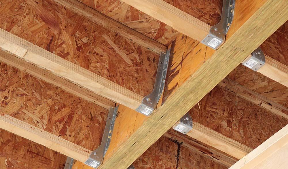
41 Joist to Beam Connector Roof to Wall Connection Roof framing to wall connection with lightweight metal connectors. (In some cases the wall sheathing can be used to make this connection.) Roof framing trusses or lumber framing Uplift Shear Double top plate Framing anchors with uplift and shear capacity 41


42 I-Joists in Simple Span I-joists in Simple Span I-Joist Trademark 42


43 I-Joists in Simple Span I-Joists in Multiple Span 43


44 I-Joists in Multiple Span I-Joists in Commercial Buildings 44


45 Design Properties Structural Composite Lumber Photo courtesy of Pacific Woodtech Corporation 45
 2. MOE (e.g. 2.0E or 1.3E) 3. Trademark or tradename 4. Type (e.g. LVL, OSL, LSL) 5.")
46 Pre-engineered Connectors Top or face mount Product specific Use correct nail Fill all holes Ensure proper fastener penetration Joist and beam hangers SCL Specification Specification Contents: 1. Size (width and depth) 2. MOE (e.g. 2.0E or 1.3E) 3. Trademark or tradename 4. Type (e.g. LVL, OSL, LSL) 5. Additional information Length Quantity 46
47 I-Joist Specification Specification Contents: 1. Depth (9-1/2'', 11-7/8'', 14'', 16'') 2. Trademark or trade name 3. Series 4. Additional information Length Quantity Rim Board Specification Specification Contents: 1. Product thickness (1'', 1-1/8'', etc.) 2. Depth (9-1/2'', 11-7/8'', 14'', 16'') 3. APA EWS or Manufacturer trademark 4. Performance Rated Rim Board Grade 5. Additional information Board lengths Number of members 47
48 Training Objectives Review Types of loads on building components Designing for load paths Deflection and calculated spans of I-Joists Simple and Multiple spans Specifying engineered wood products Questions? 48
49 Engineered Wood Products Simplified Module C I-joist Floor Framing and Rim Board Construction Details New England Building Officials Education Associations 50 th Conference October 4, 2016 Robert A. Kuserk, PE Training Objectives Upon completing this training students will be able to identify and describe Best practices in designing engineered wood floor systems Recommendations for Rim Board in I-joist floor systems Proper techniques for notching and drilling I- joists and Rim Board Correct use of web stiffeners, squash blocks and blocking for I-joist floors 49

50 Irregular I-Joist Layout I-Joist Layout Avoid Unequal Spans Avoid Unequal Spacing Unequal spans and spacing leads to uneven floor stiffness, perceived as soft spots 50


51 I-Joist Layout Use Similar Spans Use Similar Spacing Which Leads to Consistent Performance Framing Engineered Wood Floors Typical Performance Rated I-Joist Floor Framing And Construction Some framing requirements such as erection bracing and blocking panels have been omitted for clarity. 1g Glulam or Structural Composite Lumber (SCL) headers 1d 1e Figures 3, 4, 5a, 5b and 5d Holes may be cut in web for plumbing, wiring and duct work. See Table 3 and Figure 6. Note: Never cut or notch flanges. Glulam or multiple SCL headers Figures 3, 4, 5a, 5b and 5d 1b 1c 1j Use hangers recognized in current code evaluation reports 1h 1j 1k 1m 1p 1a 1n 1f APA Performance Rated I-Joists, Form Z725 51

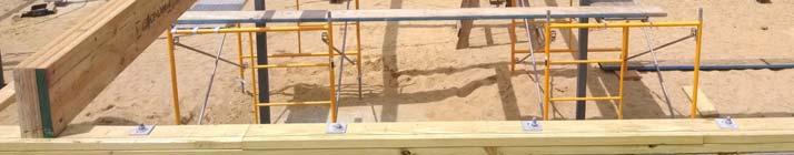
52 APA Rated Rim Board 1b APA Rim Board Install as joists are set 8d common or box nails at top and bottom flange One 8d face nail at each side of floor joist Attach Rim Board to top plate with 8d common or box 6'' o.c. APA Rated Rim Board Vertical Load Capacities APA Performance Rated I-Joists, Form Z725, Detail 1b 52

53 I-Joist Blocking Panel 1a I-Joist blocking panel with capacity to transfer uniform vertical load of 2000 plf. Install as joists are set Attach floor joist to top plate 8d 6 o.c. to top plate I-Joist Rim Joist 1c I-joist Rim Joist- Install as joists are set Attach rim joist to floor joists with one nail at top and bottom Attach floor joist to plate with one 8d face nail at each side at bearing Minimum 1-3/4'' bearing required Attach Rim joist to top plate with 8d common or box 6'' o.c. 53


54 Engineered Rim Board Technical Topics: Wood I-Joists and APA Performance Rated Rim Boards FormTT-022 Solid Sawn Rim Board Technical Topics: Wood I-Joists and APA Performance Rated Rim Boards FormTT
55 APA Rated Rim Board Hole Specifications Rim Board Depth (in.) Maximum Allowable Hole Size (in.) (2/3 height maximum) Minimum Length of Rim Board Segment for the Maximum Allowable Hole Size (in.) 9-1/2 6-1/ /8 7-3/ / /2 84 Hole of 1-1/2" or less in diameter allowed d1 d2 <d1 Rim Board 2d 1 All holes shall be cut in a workman-like manner. APA Rated Rim Board Hole Specifications Rim Board Near Concentrated Vertical Load Concentrated load 2/3 h maximum h h Rim Board 55


56 APA Rated Rim Board Over Openings Rim Boards may be used to span up to 4 feet in length, depending on the applied loads on the opening. For greater spans and additional loads, consider other engineered wood products, such as LVL. Edgewise Bending Properties Grade F be E e F ve C c e Rim Board and Rim Board Plus , Do not cut holes in Rim Board over opening except for 1-1/2'' or less in size. APA Performance Rated Rim Boards, Form W345 Integrated APA Rated Rim Board Header Allowable Loads For APA Rim Board And Rim Board (a, b, c, d, e, f) Plus Used As Headers (LOAD DURATION FACTOR = 1.0) APA Performance Rated Rim Boards, Form W345 56
 Continuous APA Rim Board or SCL across opening Stud (typ.) Cripple stud (typ.")

57 Integrated APA Rated Rim Board Header Integrated Rim Header For 2x6 Walls I-joists - 24" oc Double top plate or single plate per designer No Rim Board-joints or holes within 12" of opening Face- or top-mount hanger (typ.) Continuous APA Rim Board or SCL across opening Stud (typ.) Cripple stud (typ.) King stud Non-structural Header Maximum Allowable Span is 4' with single or double APA Rim Board King stud Double APA Rim Board or SCL as required over opening Non-structural framing Note: The number of king studs required to transfer gravity and wind loads may increase with larger opening. Check with designer. No joints within span of Rim Board header or within 12" of opening. Detail courtesy of NAHB Research Center. Ledger Board Attachment Existing stud wall Rim Board Floor sheathing Wood I-joist Exterior sheathing Remove siding at ledger prior to installation Continuous flashing extending at least 3" past joist hanger 2" min. 1-5/8" min. 5" max. 2" min. 1/2" diameter lag screws or thru-bolts with washers Deck joist Joist hanger Existing foundation wall 2x ledger board (preservativetreated); must be greater than or equal to the depth of the deck joist APA Performance Rated Rim Boards, Form W345 57


58 Vertical Load Transfer Wall Load Above Stacking Walls Potential Failure Modes: Buckling of web Knifing through flange Vertical Load Transfer 1d I-joist or Rim Board blocking panels + 1/16" for squash blocks Squash block 58


59 Vertical Load Transfer APA Performance Rated I-Joists, Form Z725 Vertical Load Transfer 1e Squash block cross-section must equal or exceed column crosssection. Install before joists are sheathed. 59


60 Vertical Load Transfer 1f Use single I-joist for loads up to 2000 plf, double for loads up to 4000 plf. Wall sheathing, as required Provide backer for siding attachment unless nailable sheathing is used Vertical Load Transfer 1g Load bearing wall above must align vertically with the wall below. Offset wall are not covered by this detail. Blocking required over all interior supports or when joists are not continuous Floor joist attachment per detail 1b I-joists blocking panel per 1a. Install as joists are set. 8d nails at 6" o.c. to top plate 60

 Joist Hanger Connections 1h Backer Blocks (Blocks")
61 Joist Hanger Connections 1h Top- or face-mounted hanger Double I-joist header Backer block needed if hanger exceeds 250 lbs. Use three 10d nails to attach backer blocks through webs and filler blocks. Note: Unless hanger sides laterally support the top flange, bearing web stiffeners shall be used. Filler block per Figure 1p Backer block required (both sides for face-mounted hangers) Joist Hanger Connections 1h Backer Blocks (Blocks must be long enough to permit required nailing without splitting) APA Performance Rated I-Joists, Form Z725 61

62 Double Joist Assembly 1p Filler block 1/8" to 1/4" gap between top flange and filler block Offset nails from opposite face Double Joist Assembly 1p Fill Block Requirements For Double I-Joist Construction APA Performance Rated I-Joists, Form Z725 62
")


63 Joist Hanger Connections 1i Single or multiple structural composite lumber (SCL) beams (LVL, LSL, or OSL. For attachment schedules for multiple SCL beams see the manufacturer s recommendations Top or face-mounted hanger installer per manufacturer s recommendations Joist Hanger Connections Top mount hanger Photo Courtesy of Pacific Woodtech Corporation 63


64 Joist Hanger Connections Joist Hanger Connections 1k 2x plate attached flush to the inside of the non-nailable bearing wall or beam Top or face-mounted hanger installer per manufacturer s recommendations APA Performance Rated I-Joists, Form Z725 64


65 Joist Hanger Connections 1m Multiple I-joist header with full depth filler block. Multiple SCL may also be used. Attach backer block according to detail 1h and nail with twelve 10d nails Install hanger per manufacturer s recommendations Filler block per Figure 1p Joist Hanger Connections 65

 8d box or common nails clinched No Gap")
 8d box or common nails, 10d required for")
66 Web Stiffeners Web Stiffeners Flange width 1-3/4" or less Flange width greater than 1-3/4" Approx. 2" 1/8" to 1/4 Gap Approx. 2" 1/8" to 1/4 Gap Approx. 2" Clinch (4) 8d box or common nails clinched No Gap Approx. 2" (4) 8d box or common nails, 10d required for I-joists with 3-1/2" flange width (PRI-80s and PRI-90s) No Gap 66
 (BEARING STIFFINER) (End Bearing) Gap Gap Tight Joint No")

67 Web Stiffeners Tight Joint No Gap LOAD STIFFENER (Concentrated Load) (BEARING STIFFINER) (End Bearing) Gap Gap Tight Joint No Gap APA Performance Rated I-Joists, Form Z725 Web Stiffeners Stiffener Size Requirements APA Performance Rated I-Joists, Form Z725 67


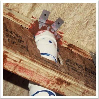
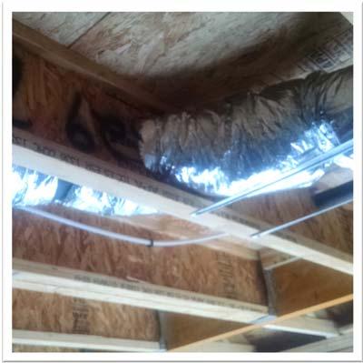
68 Cutting Holes in I-Joists Never drill, cut or notch the flange or over-cut the web Cutting Holes in I-Joists Limit 3 maximum size holes per span A 1-1/2 inch hole can be placed anywhere in the web, provided it has the required distance from adjacent holes Keep a minimum 1/8 inch between top or bottom of a hole and the flanges I-Joist top and bottom flanges must never be cut, notched, or otherwise modified Whenever possible field-cut holes should be centered on the middle of the web The max. size hole that can be cut into an I-joist web shall equal the clear distance between the flanges of the I-joist minus ¼ inch. All holes shall be cut in a workman-like manner. 68

69 Cutting Holes in I-Joists Moments are Max. at L C Compression Tension LC LC Shear Forces are Maximum At Supports Cutting Holes in I-Joists Minimum distance from face of support to the center of hole. See Table 5. See Rule 12, pg 19 Z725, 3/4x diameter 2x diameter of larger hole Knockouts are pre-scored holes often provided by I-joist manufacturers for the contractor s convenience to install electrical or small plumbing lines. They are typically 1-3/8 to 1-3/4 inches in diameter, and are spaced 12 to 24 inches on center along the length of the I-joist. Where possible, it is preferable to use knockouts instead of field-cutting holes. APA Performance Rated I-Joists, Form Z725 69


70 Cutting Holes in I-Joists Simple Or Multiple Span For Dead Loads Up To 10 psf And Live Loads Up To 40 psf 70
 x 6.92 ft = 4.")
71 D reduced = (9.58 ft ft) x 6.92 ft = 4.6 ft or about 4' 7" 71


72 Cantilevered Engineered Wood Floors Sheathing Reinforcement One Side APA Rim Board or wood structural panel closure (minimum 23/32 Performance Category), attach per Detail 1b PRI blocking panel or APA Rim Board blocking, attach per Detail 1g 6" 8d nails 3-1/2" min. bearing required Attach I-joist to plate per Detail 1b APA Performance Rated I-Joists, Form Z725 Short Cantilever in Engineered Wood Floors APA Performance Rated I-Joists, Form Z725 72


73 Beveled End Cuts 1n Never bevel cut an I-joist beyond the inside face of the bearing wall Attach I-joists per detail 1b Blocking is always required at the end of I-joists over bearing for lateral support. Not shown here for clarity Stairwell Openings Trimmer Header Technical Note, Stairwell Openings in APA PRI I-Joist Floors, Form Z705 73

74 Other Openings Training Objectives Review Best practices in designing engineered wood floor systems Recommendations on Rim Board for I-joist floor systems Proper techniques for notching and drilling I- joists and Rim Board Correct use of web stiffeners, squash blocks and blocking for I-joist floors 74
 620-7400")


75 APA Resources (253) APA Resources Help Desk Field personnel located around North America 75


76 APA Resources Help desk Field personnel located around North America Websites Designers Circle Wood Products Manufacturing 76
77 APA Resources Help desk Field personnel located around North America Websites Designers Circle Literature APA Resources Help Desk Field personnel located around North America Websites Designers Circle Literature 77
78 Questions? 78