Slide 1. Slide 2. Slide 3. Pentagon Source Material: Mlaker et. al., The Pentagon Building Performance Report, ASCE, 2002.
|
|
|
- Marshall Carter
- 5 years ago
- Views:
Transcription
1 Slide 1 Columns in Buildings Subject to Attack The Pentagon (September 11, 2001) The Murrah Building (April 19, 1995) In one sense, these two buildings provide a roughly equivalent set of circumstances for comparison; both are (or were) reinforced concrete buildings subjected to extreme events. However there were significant differences in the nature of the attacks and in the materials properties, layout, and design of each building. The comparison given here is qualitative only. Slide 2 Background of the Pentagon Built from million sq ft of floor space. Composed of five rings separated by light wells. Five stories high. Reinforced concrete frame with masonry and limestone exterior. North Pentagon Source Material: Mlaker et. al., The Pentagon Building Performance Report, ASCE, Slide 3 Section Through the Rings AE Drive Ring E Ring D Ring C Ring B Ring A
2 Slide 4 Framing Plan Expansion Joint Girders to 11 Exterior Wall Shown is a plan view of the beams and girders for an outer section of ring E. The exterior of ring E would be on the right hand side of the figure. Note that the exterior wall has extra columns. These are necessary to support the weight of the heavy limestone cladding. Beams Columns Slide 5 The Original Building Design - f c = 2500 psi, Grade 40 reinforcement 1930 s ACI Building Code (ACI ) No live load reduction was used in anticipation that the building would be used for storage of records following WW II. The structure was designed for a full live load of 150 psf. Slide 6 Column Details Girder ρ = to ρ s = minimum 1.5 concrete cover to 24 square Footing Note that the columns used spiral confinement. Spiral confinement was used so that the columns could have a higher allowable stress (1930 s RC design would have been an allowable stress procedure) to hold the high specified live load. Spiral confinement was not used for any of its other benefits: enhanced ductility and load redistribution capability.
3 Slide 7 Girder Details Close Stirrup Spacing Throughout Length Bottom Bars Extended into Columns The girder and beam details provided ductile performance and redistribution of load. Slide 8 The September 11, 2001 Attack: The aircraft was a Boeing (wingspan of 125 and tail height of 44.5 ) At the time of the impact, it was travelling at 780 ft/sec, weighed 181,520 lb, and had 5,300 gal of fuel. (kinetic energy = 1720 million ft*lb) The aircraft debris decelerated at a rate of approximately 30g as it impacted with the building. Slide 9 The September 11, 2001 Attack: 64 people aboard the aircraft and 125 people in the building were killed. The aircraft struck a recently renovated portion of the building (additional facade support and blast resistant windows had been installed) Structural damage from impact, explosion, and sustained fire.


4 Slide 10 Corridor 4 is on the right, Corridor 5 is on the left. Point out the extent of fire damage to the structure. The furthest spread occurred along the roofs ironically facilitated by the concrete roof which prevented fire fighters from accessing the crawl space where the fire was. Slide 11 Ring E The figure shows the wedge of damage created by the impact. Damage and debris were found approximately 310 feet from the point of initial impact - a hole in the wall of ring C leading to AE drive. 310 Ring D Ring C The heaviest objects from the plane were found the furthest along the impact trail. The front landing gear and the black box were found at the hole to AE drive. Additionally, the plane inverted itself as it decelerated, with items at the front of the craft deposited near the head of the impact trail and items at the back of the craft found further along. Human remains belonging to the terrorists and items belonging to the cockpit were found in ring E. Objects from the rear of the fuselage were found in rings D and C. Slide 12 For 20 min. following the impact, the structure stood as rendered below. Figure 3.10, page 17 from the Building


 was estimated to")


5 Slide 13 Slide 14 Figure 3.9, page 16 from the Building The damaged portion of the Pentagon collapsed after 20 min. due to fire damage inflicted to the structural concrete 86% of the jet fuel (30,400 lb) was estimated to have entered the building Estimations place the peak temperature of the fire at 1500 to 1600 of Slide 15 Figure 1.3, page 4 from the Building


6 Slide 16 After removal of debris: Figure 5.1, page 24 from the Building Slide 17 Figure 5.4, page 25 from the Building Slide 18 Figure 5.8, page 27 from the Building Impact of the right wing


7 Slide 19 Hole to AE Drive Figure 5.16, page 30 from the Building 310 ft from the point of impact Slide 20 Column Damage Buried During the Collapse Damaged Beyond Function Significant Impairment Some Impairment Minor Damage No Damage Impact Zone Ring E Ring D Ring C After Figure 7.9, page 53 from the Building Hole to AE Drive Slide 21 Damaged Beyond Function - Several columns were found severed from their connections or otherwise missing a portion of their height Figure 7.5a, page 48 from the Building


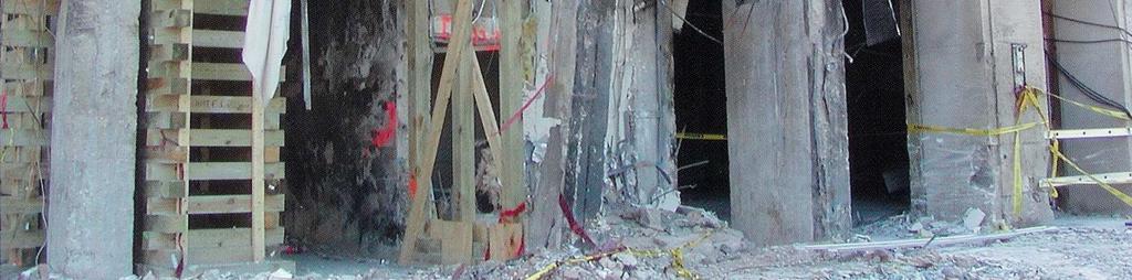
8 Slide 22 Note the necking of the longitudinal reinforcement at the fracture points Figure 7.5b, page 48 from the Building Slide 23 Two columns found in this condition: no concrete left just an empty cage. Slide 24 Significant Impairment - Severe deformation of the column and loss of the majority of cover Many columns had significant rotation at top and bottom connections Figure 5.21, page 32 from the Building


9 Slide 25 Loss of the cover impaired the ability of the columns to endure the fire Note the discoloration of the concrete from the fire Figure 5.20, page 31 from the Building Slide 26 Some Impairment - Partial loss of cover Insignificant deformation of the column Figure 5.18, page 31 from the Building General integrity of the core was maintained Slide 27 Fire Damaged Column - This column shows signs of fire damage: discoloration and spalling of concrete Fire damage can cause loss of concrete strength even when outward signs of damage seem minor Figure 5.19, page 31 from the Building
10 Slide 28 Reconstruction Slide 29 Eventually, they rebuilt rings E, D, and C between corridors 4 and 5. Slide 30 Background Designed in the early 1970 s Built story office building with attached parking structure This photo is from Corley et. al., Fig. 1, pg Murrah Source Material: Questions of Design Follow Terror Blast, ENR, Vol. 234, No. 17, May 1, 1995, pg Pendergast, J., Oklahoma City Aftermath, Civil Engineering, Vol. 65, No. 10, Oct. 1995, pg Corley, et. al., The Oklahoma City Bombing: Summary and Recommendations for Multihazard Mitigation, ASCE J. of Perf. of Constructed Facilities, Vol. 12, No. 3, Aug. 1998, pg Mlakar, et. al., The Oklahoma City Bombing: Analysis of Blast Damage to the Murrah Building, ASCE J. of Perf. of Constructed Facilities, Vol. 12, No. 3, Aug. 1998, pg Sozen, et. al., The Oklahoma City Bombing:
11 Structure and Mechanisms of the Murrah Building, ASCE J. of Perf. of Constructed Facilities, Vol. 12, No. 3, Aug. 1998, pg Testimony of Dr. Gene Corley Before the House of Representatives, transcript available at corley.htm Hinman, Eve E. and Hammond, David J., Lessons from the Oklahoma City Bombing, ASCE, Special Publication, Slide 31 Layout 1st and 2nd Floors Shown 20 Bay Spacing G12 G16 G20 G Four large columns along the south side (G12, G16, G20, and G24) were used to create an open front along N.W. 5th Street. These columns extended for the 1st and 2nd floor and supported a transfer girder upon which sat smaller column framing similar to the spacing along the two interior column lines shown above. North 30 Other notes: The building used one-way slabs for the floors with beams running north-south. The outer walls on the east and west, and the rear stairwell of the building contained structural shear walls. Slide 32 Column Details G12, G16, G20, and G Height f c = 4000 psi actual measured at 4900 psi and higher Gr. 60 longitudinal bars Gr. 40 ties The four large northern exterior columns were most effected by the bomb blast and hence the columns of interest here. The columns had a 3.5% reinforcement ratio (high). #10 s (20 total) #4 Ties at 10 on center
 Slide 34 The April 19, 1995 Attack: Caused air blast and ground shock")
 $652 million property damage (Extensive broken glass, damaged facades, and structural damage to surrounding buildings) Slide 35 This photo is from ENR, pg. 18.")
12 Slide 33 The April 19, 1995 Attack: Homemade truck bomb exploded just outside the north face of the building 4800 lb of ammonium nitrate and fuel oil Approximately a 5,000 lb TNT equivalent explosion (Bomb yield estimated by the crater size: 7 deep, 28 diameter) Slide 34 The April 19, 1995 Attack: Caused air blast and ground shock loading on the surrounding buildings 163 people were killed in the building, primarily by progressive collapse of the building (4 other people killed outside the building) $652 million property damage (Extensive broken glass, damaged facades, and structural damage to surrounding buildings) Slide 35 This photo is from ENR, pg. 18. North Bomb Crater
13 Slide Structural Damage Collapsed Structure Broken Glass/Doors Unharmed Structure This figure taken from Hinman, Fig Building 9 is the Murrah Building Building 6 is the Athenian Restaurant North Slide 37 North Athenium Restaurant 1 fatality Slide 38 The day care center was on the 2 nd floor.
14 Slide 39 This figure taken from ENR, pg. 11. The loss of three critical columns caused the extensive damage: 9th 8th 7th 6th G24, G20, and G16 5th 4th 3rd 2nd 1st G24 G20 G16 G12 Slide 40 Peak Over-Pressures Approximate duration of pressure load was 5 milliseconds. This figure taken from Mlaker et. al., Fig. 5, pg psi 40 psi 60 psi 80 psi 100 psi 10,000 psi Slide 41 Failure of Columns G24, G20, and G16: G20 was destroyed by brisant effects - shattering of the concrete at the material level; No discernable remains were found of G20 G16 and G24 failed in shear With the loss of G16, G20, and G24, the transfer girder supporting the overlying structure collapsed along with portions of the 7 floors directly overhead Brisance is a general term referring to shattering of any brittle material, not a term particularly related to concrete. Column G20 would not have survived in any case unless it was shielded in some way from the high overpressure of the bomb. Columns G16 and G24 may have survived if they had higher shear capacity and flexural ductility - such as if they had spiral confinement rather than ties.


15 Slide 42 This photo is from Pendergast, pg. 43. Transfer Girder Column G12 Slide 43 This photo is from Hinman, Fig Transfer Girder Column G12 Slide 44 Conclusions of the Investigative Engineers: if the 1976 Murrah building had been built using today s seismic building design details, as much as 50 to 80 percent of the structural damage, and presumably the fatalities, could have been prevented. the bomb blast to the Murrah building was not devastating by itself - it just so happened that it was located at a critical point which undermined the whole structure of the building. Gene Corley - Testimony before the Public Buildings and Economic Development Subcommitte of the US. House of Representatives
16 Slide 45 Conclusions of the Investigative Engineers: The use of spiral confinement would have greatly enhanced the shear capacity of columns G16 and G24, possibly allowing them to survive the attack Enhancements to the details of the slabs and girders would include more continuity of reinforcement The cost of these measures is minor compared to the overall cost of the building Slide 46 Other Factors: Placement of the building from the street - additional space between the building and the street would have greatly reduced the overpressure load. Framing Plan - less reliance on individual critical elements. A less open front with more columns would have made the structure less dependant on the survival of any one column element. Slab Performance the blast caused pressure underneath the slabs, pushing them upward and subjecting them to moments in reverse of those they were designed for. Slide 47 Comparison - Pentagon vs Murrah Building The performance of the Pentagon is generally considered ideal in comparison to the Murrah building. The Pentagon lost more columns from the initial attack, but overall lost less proportion of tributary area supported by those columns. The ductile performance of the Pentagon columns, beams, and joints played a key role in it s performance.