Spray Foam and the Building Codes
|
|
|
- Justin White
- 5 years ago
- Views:
Transcription
1 Designing For The Future Spray Foam and the Building Codes New England Building Officials October 7, Randy Nicklas, Senior Engineer Presentation Objectives Why Spray Polyurethane Foam (SPF) use is expanding rapidly 1. Advances in Building Science Knowledge 2. Moisture Issues - Liability 3. Energy Performance - DOE 50% Solution Review Building Science (Physics) Heat, Air and Moisture Flows Open Cell and Closed Cell - Differences and Applications 1
2 Presentation Objectives Building Codes: IRC - IBC - IECC Thermal and Ignition Barriers Unvented Attics Building Durability Energy Conservation Introduction: The Icynene Insulation Systems Building Code Objectives Health Safety Durability Comfort Affordability 2


3 SECTION 1 Section 1: WHY: Building Science Heat, Air and Moisture Flows Section 2: Spray Foam Insulation Section 3: Building Codes And SPF ICC Zones Moist 3

 Air Movement - Within the Cavity - Across The")
4 Building Science Water Tight, Air Tight, Vapor Permeable Box of Air Controlled Environment Outside Air 0 O to 90 O F // % RH Equilibrium Inside = Outside Inside Air (70 O F // 30-50% RH) Controlled Fresh Air Exchange Mechanical Ventilation Filtration Physics Rule HAM Sandwich Insulation Systems Stop (Retard) Air Movement - Within the Cavity - Across The Envelope Air Leakage 4
5 Moisture Control and SPF 90% OF ALL BUILDING FAILURES IN THE U.S. ARE RELATED TO MOISTURE ASHRAE is the American Society of Heating, Refrigeration, and Air Conditioning Engineers Moisture Control Priority 1. Bulk Moisture / Water Foundation, Walls, Roof, & Plumbing 2. Water Vapor Air Transport (Units: Pounds) Vapor Diffusion (Units: Nano grams) 5
6 Drainage Plane Moisture / Frost accumulation on inside face of exterior sheathing Exterior Sheathing Exterior Fiberglass/Cellulose Insulation (Air Permeable) 40 O 70 o Temperature Gradient Moisture Transport Air Leakage Interior 1/2" Gypsum Wallboard with Latex Paint (Vapor Permeable) Dew Point Temperature 51 0 F (100% RH) Heating Season Drainage Plane 1/2" Gypsum Wallboard (Sheetrock) Exterior Sheathing Exterior 90 0 F - 80 % RH Moisture Transport Air Leakage Air-Permeable Insulation Fiberglass/Cellulose Temperature Gradient Interior % RH Moisture - Mold accumulation on exterior face of sheetrock or vinyl wallpaper Dew Point Temperature F (100% RH) Cooling Season 6
 Mixed Climate Cooling/Heating Season")
7 Exterior 90 0 F - 80 % RH Interior 70 0 F - 50% RH Spray Foam Insulation (Air Impermeable) Moisture Transport Air Leakage Moisture Transport Air Leakage Dew Point Temperature (100% RH) Mixed Climate Cooling/Heating Season 7

8 Air Leakage Air Leakage 25-40% Heat Loss/Gain 8

9 IRC Section Unvented Attics Air Impermeable Insulation leakage req d to be <.02 L/s-m (ASTM E 283) L/s-m Al Foil Extruded Polystyrene NM NM 6 Mil Polyethylene NM 1/2 Plywood.0067 Open / Closed 1/2 Gypsum Wallboard.0196 Expanded Polystyrene-Type Plain Fiberboard.8220 Expanded Polystyrene-Type Fiberglass Insulation Cellulose Insulation, Spray-on Air Impermeable Air Permeable.02 Solplan Review 2000 VAPOR RETARDER CLASS A measure of the ability of a material or assembly to limit the amount of moisture that passes through that material or assembly. Vapor retarder class shall be defined using the desiccant method with Procedure A of ASTM E 96 as follows: Class I: 0.1 perm or less Class II: 0.1 < perm < 1.0 perm (Req d ICC Zones 5-8) Class III: 1.0 < perm < 10 perm 9


10 Air-Tight Construction Continuous Air Barrier Air leakage > 25-40% Ventilation Fresh Air - In Stale Air - Out 10
11 Is it possible to build a house too tight? You can NEVER build a house too tight! (But you can easily under-ventilate one!) ASHRAE Single Family Ventilation CFM fan = (0.01 x A floor ) + (7.5 x (# bedrooms + 1)) Floor Area (ft 2 ) OR Table M (1) BEDROOMS >7 < >
12 ASHRAE New Construction Calculation Base formula, step by step: 2500 SqFt - 3 Bedrooms 1. Multiply the # of bedrooms + 1 by 7.5 CFM per person: 3BR: 4 people x 7.5 CFM/person = 30 CFM 2. Calculate 1 CFM per 100 square feet of floor area: 2500 sf: 1 CFM x (2500/100) ft 2 required CFM = 25 CFM or.01 CFM x 2500 ft 2 required CFM = 25 CFM 3. Add them together: 30 CFM + 25 CFM = 55 CFM continuous 23 Exhaust Ventilation System Fresh 80 Vents or Trickle Vent Windows in each Room + Exhaust Fan
13 Supply Ventilation System - Air Supply Duct to Furnace Return Duct + - Supply Furnace Return Balanced Ventilation System Exhaust Fan Supply Fan 13
 14")
14 Energy Recovery Ventilation - ERV System Supply to Bedrooms, Living, Dining, Office, etc.. Hoods Minimum. 6' Apart ERV Exhaust from Baths, Kitchen and Laundry Stand Alone System ( HWBB, Radiant Floor, EBB ) 14

15 Insulation Performance R-Value Testing ASTM C 518 (Guarded Hot Box) Data R-Value testing takes place in a controlled laboratory environment It assumes steady state conditions It assumes a perfect installation It ignores all other forms of heat loss 15


16 Jobsite Realities vs. Laboratory Tests Oak Ridge National Lab 16
 Performance Path to Meeting the Code 405.3 Performance-based compliance.")
17 Conductive Heat Flow Reduction 9/2/2016 Fourier s Law of Thermodynamics 82% 90% 93% 95% 96% 96% 97% 97% 98% 98% 98% 98% % R-Value of Insulated Space (hr ft2 of / Btu inch) Performance Path to Meeting the Code Performance-based compliance. Compliance based on simulated energy performance requires that a proposed residence (proposed design) be shown to have an annual energy cost that is less than or equal to the annual energy cost of the standard reference design. Energy prices shall be taken from a source approved by the code official, such as the Department of Energy, Energy Information Administration's State Energy Price and Expenditure Report. Code officials shall be permitted to require time-of-use pricing in energy cost calculations. 17


18 SECTION 2 Section 1: WHY: Building Science Heat, Air and Moisture Flows Section 2: Spray Foam Insulation Section 3: Building Codes And SPF Changes in Insulation Technology Traditional Most of us have grown up with fiberglass being the most popular type of Modern insulation product. It is fair to say that prior to the development and refinement of spray foam insulation technology, fiberglass (seen here on the left) for the last 50 years was always the product of choice and was typically installed by a carpenter. Fast forward to today, and you ll see spray foam insulation (seen here on the right) becoming more of a mainstream product with the installation being performed by a technician dressed in what almost looks like a space suit. 18


19 Open Cell Open Cell Open Cell SPF is specified and installed in both residential and commercial applications. It comes in a light or medium density, 0.5 lbs. 1.5 lbs. per cubic foot. Open Cell Light and Medium Density, 0.5 to 1.5 lb/cu Ft. Closed Cell Closed Cell Closed Cell SPF is also specified and installed in both residential and commercial applications. It is mostly 2 lbs. per cubic foot, medium density, and can also come in a high density at 3 lbs. Closed Cell 2 lb/cu Ft - Medium Density 19
20 Open Cell / Closed Cell Insulation Comparison Light Density Open Cell: Spray-in-place and Air Barrier Vapor Semi-Permeable 9 Perms/Class III VDR Flexible Does not sustain mold Drains water through R per inch No synthetic blowing agent Water Blown Medium Density Closed Cell: Spray-in-place Insulation and Air Barrier Low Vapor Permeance < 1 Perm (Class II VDR) Vapor Barrier Rigid Does not sustain mold Rejects bulk water R per inch Synthetic Blowing Agent HFC 245FA Zero ODP Key Advantages of Open Cell Flexible, maintains an air seal during movement/shifting of the building over time Semi-vapor permeable supports bi-directional drying of assemblies (Mixed Climates) Class III V.D.R. ( > 1 perm ) Roof Leak Detection / Gravity Issue No Wicking / Cell Structure - No Capillary Action Soft texture and open cell structure allows for greater sound abatement vs. a hard rigid foam 100:1 Expansion Ratio - (99% air) requires less material, reduced environmental impact, less expensive - $/R-value 20
21 Key Advantages of Closed Cell Higher R-Value per inch - Limited spaces Higher tensile strength - Rigid composition adds wall racking strength Lower vapor permeance, Class II V.D.R. ( < 1 perm ) Required in ICC Zones 5-8 Rejects bulk water, WRB- exterior applications, Continuous Insulation Impact Resistance R-5.8 to day aged R-value Air Leakage Control Primary Benefits: Helps control condensation Helps control moisture related wood rot problems: mold, corrosion, Improves indoor air quality control Health of building & occupant Controls drafts Improves Energy Conservation Compliance with the New Building Codes 21

22 SECTION 3 Section 1: WHY: Section 1: Building Science Heat, Air and Moisture Flows Section 2: Spray Foam Insulation Section 3: Building Codes And SPF 2009 IRC Energy Conservation Mandatory 22

23 2009 IRC Energy Conservation & IRC Air Barrier/Insulation Installation 23

24 2012 ICC IRC & IECC (IRC Chapter 11 Refers to IECC) Thermal Values Zone Ceiling Walls Basements or / or / or / or /19 7/ or /19 Walls 20 or 13+5 means R-20 Cavity Fill or R-13 Cavity Fill plus R-5 continuous insulation on the outside of the studs. Basements 5/13, 10/13 or 15/19 means first number is used if insulation is continuous, second number is used if insulation is installed in studs. Building Envelope Air Tightness (2009 IRC Visual or Testing Option) All New residential construction must be blower door tested. Air tightness requirement is 3 ACH50 in ICC Zones 3 8 Air tightness requirement is 5 ACH50 in ICC Zones 1 and 2 24


25 2012 IECC Commercial Text Unvented Attics 2009/15 IRC - R806.4/5 (Since 2004 Supplement) 25


26 Moisture Movement Exterior 25 0 F - 80 % RH Shingles Exterior Sheathing Roofing Paper (1 Perm) Air Impermeable Insulation -ASTM 283 Air Barrier Dew Point Temperature F Temperature Gradient Interior % RH Moisture Transport Air Leakage Heating Season Moisture Movement Exterior 90 0 F - 80 % RH Shingles Exterior Sheathing Roofing Paper Air Impermeable Insulation -ASTM 283 Air Barrier Dew Point Temperature F Temperature Gradient Interior % RH Moisture Transport Air Leakage Cooling Season 26


27 Unvented Attic Assemblies R-50 - Loose fill Fiberglass with Vented Attic 27


28 R-25 Open Cell Foam in Unvented Attic - 3 Weeks 28

29 AC 377 / Utilities Mechanical Equipment Electrical Wiring Fans Plumbing Gas or Electric Water Heaters Gas or Electric Water Furnaces Note: C/A per IMC Section

30 Unvented Attic Assemblies In ICC Climate Zones 5,6,7 and 8 Any air impermeable insulation shall be a vapor retarder, - Class II Vapor Diffusion Retarder (VDR) < 1 Perm OR Shall have a Class II VDR coating or covering in direct contact with the underside of the insulation. Air impermeable Insulation or Rigid Board Insulation R-value Requirements - Table R806.4 ICC Zone 5 / R-20 ICC Zone 6 / R-25 ICC Zone 7 / R-30 ICC Zone 8 / R-35 SPF and Fire Code Considerations 30
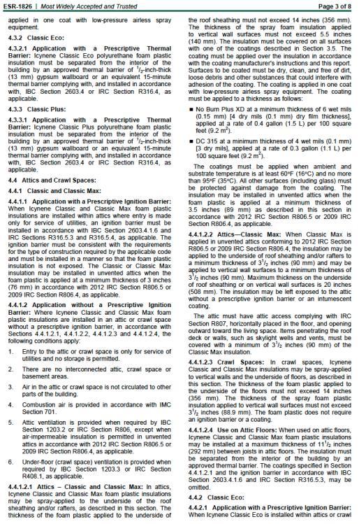
31 IRC Section Foam Plastic R316.4 Thermal barrier. Unless otherwise allowed in Section R316.5 or Section R316.6, foam plastic shall be separated from the interior of a building by an approved thermal barrier of minimum 1/2 inch (12.7 mm) gypsum wallboard or an approved finish material equivalent to a thermal barrier material that will limit the average temperature rise of the unexposed surface to no more than 250 F (139 C) after 15 minutes of fire exposure complying with the ASTM E 119 or UL 263 standard time temperature curve. The thermal barrier shall be installed in such a manner that it will remain in place for 15 minutes based on NFPA 286 with the acceptance criteria of Section R , FM 4880, UL 1040 or UL IRC Section Attics and Crawlspaces R Attics (R Crawl Spaces). The thermal barrier specified in Section R314.4 is not required where all of the following apply: 1. Attic access is required by Section R The space is entered only for purposes of repairs or maintenance. 2. The foam plastic insulation is protected against ignition using one of the following ignition barrier materials: /2-inch-thick (38 mm) mineral fiber insulation; /4-inch-thick (6.4 mm) wood structural panels; /8-inch(9.5 mm) particleboard; /4-inch (6.4 mm) hardboard; /8-inch (9.5 mm) gypsum board; or 3.6. Corrosion-resistant steel having a base metal thickness of inch (0.406 mm). The above ignition barrier is not required where the foam plastic insulation has been tested in accordance with Section R
32 IRC Section Foam Plastic R316.6 Specific Approval. Foam plastic not meeting the requirements of Sections R316.3 through R316.5 shall be specifically approved on the basis of one of the following approved tests: NFPA 286 with the acceptance criteria of Section R , FM4880, UL 723, UL 1040 or UL 1715, or fire tests related to actual end-use configurations. The specific approval shall be based on the actual end use configuration and shall be performed on the finished foam plastic assembly in the maximum thickness intended for use. Assemblies tested shall include seams, joints and other typical details used in the installation of the assembly and shall be tested in the manner intended for use. Thermal Barrier Thermal barrier. Except as provided for in Sections and , foam plastic shall be separated from the interior of a building by an approved thermal barrier of O.5-Inch(12.7 mm) gypsum wallboard or equivalent thermal barrier material that will limit the average temperature rise of the unexposed surface to not more than 250 F (I20 C) after 15 minutes of fire exposure, complying with the standard time-temperature curve of ASTM E 119. The thermal barrier shall be installed in such a manner that it will remain in place for 15 minutes based on FM 4880, UL 1040, NFPA 286 or UL Combustible concealed spaces shall comply with Section
33 Ignition Barrier Attics and crawl spaces. Within an attic or crawl space where entry is made only for service of utilities, foam plastic insulation shall be protected against ignition by l.5-inch-thick (38 mm) mineral fiber insulation; 0.25-inch-thick (6.4 mm) wood structural panel, particleboard or hardboard; inch (9.5 mm) gypsum wallboard, corrosion-resistant steel having a base metal thickness of inch (0.4 mm) or other approved material installed in such a manner that the foam plastic insulation is not exposed. The protective covering shall be consistent with the requirements for the type of construction. Thermal Barrier Special approval. Foam plastic shall not be required to comply with the requirements of Sections through where specifically approved based on large-scale tests such as, but not limited to, NFPA 286, FM 4880, UL 1040 or UL Such testing shall be related to the actual end-use configuration and be performed on the finished manufactured foam plastic assembly in the maximum thickness intended for use. Foam plastics that are used as interior finish on the basis of special tests shall also conform to the flame spread requirements of Chapter 8. Assemblies tested shall include seams, joints and other typical details used in the installation of the assembly and shall be tested in the manner intended for use 33


34 SILLS & HEADERS No ignition or thermal barrier required if less than 3 ¼ sprayed. IRC R , IBC The Plan Build Tight, Ventilate Right and Install Healthier Building Materials 34


35 Designing For The Future Questions? Thank You for Attending! Why Icynene? Icynene was the First manufacturer to offer Open cell spray foam products that do not contain harmful gases or formaldehyde. Our commitment to quality and innovation is recognized globally. Multiple commercial products meet the performance criteria of ASHRAE 90.1 Commercial Fire Tested - NFPA 285 Wall Assemblies Three Open cell and three Closed cell SPF products to meet a variety of Residential and Commercial applications. Classic Max and ProSeal Ultra Low VOC Formula: 1 Hour Re-entry and 2 Hour Re-occupancy 35
 Water Blown - Spray & Cavity Fill Formulas Classic Max")
 *Re-entry 1 Hr// Re-entry 2 HR @ 40 ACH Ventilation")

36 28 Years / 2 M+ Projects / All Climates / 41 Countries Classic LD-C 50 ESR 1826 R-3.7/in Flexible, Low Density Open Cell Foam (Original) Water Blown - Spray & Cavity Fill Formulas Classic Max LD-C 50 v2 ESR 1826 R-3.7/in (IRC, Unvented Attics / No Ignition Barrier Required) *Re-entry 1 Hr// Re-entry 2 40 ACH Ventilation Rate Classic Plus LD-C 70 ESR 1826 R-4/in MD-C 200 ESR 3199 R-6.5/in Closed Cell - Blowing Agent - HFC245FA - Zero Ozone Depletion ProSeal MD-C 200v3 ESR 3500 R-7.0/in Closed Cell- Blowing Agent - HFC245FA - 0- ODP *Re-entry 1 Hr// Re-entry 2 HR 40 ACV Ventilation Rate ProSeal Eco MD-R 210 ESR 3493 Closed Cell Blowing Agent Water R-4.8/in 36


37 37
38 38

39 Thank You 39