Kaleida Health Global Heart and Vascular Institute University at Buffalo CTRC/Incubator. Buffalo, New York. Technical Report #2
|
|
|
- Leon Booth
- 5 years ago
- Views:
Transcription

1 University at Buffalo CTRC/Incubator Buffalo, New York William McDevitt October 27, 2010
2 Table of Contents Executive Summary...3 Introduction...4 Structural System Overview...5 Foundation...5 Floor System...5 Gravity System...5 Lateral System...6 Codes and References...7 Original Design Codes...7 Thesis Design Codes...7 Materials...8 Gravity Loads...9 Design Floor Dead Loads...9 Floor Live Loads...10 Existing Floor System Composite Steel...11 Alternative Floor System 1 Flat Slab with Drop Panels...13 Alternative Floor System 2 Pre-Cast Hollow Core Plank...15 Alternative Floor System 3 One-Way Joist and Beam...17 Systems Comparison...19 Conclusion...21 Appendix...22 Appendix A: Typical Floor Plans and Elevations...23 Appendix B: Existing Floor System Composite Steel...26 Appendix C: Alternative Floor System 1 Flat Slab with Drop Panels...32 Appendix D: Alternative Floor System 2 Pre-Cast Hollow Core Plank...38 Appendix E: Alternative Floor System 3 One-Way Joist and Beam
3 Executive Summary The following document is the second technical report of senior thesis and includes information regarding the structural floor system of the Kaleida Health and University at Buffalo, Global Heart and Vascular Institute. This project will be referred to throughout this report simply as GHVI. This report includes the design and analysis of three alternative floor systems for a typical 31-6 by 31-6 interior bay on the fourth floor. These alternative floor systems include: - Flat Slab with Drop Panels - Pre-Cast Hollow Core Plank - One-Way Joist and Beam The design of the flat slab system resulted in a 10 slab with 6¼ drop panels which extend 6 in each direction from the column center line. Reinforcing was designed for the column strip and middle strip positive and negative moments, and one-way and two-way punching shear was checked. This strategy resulted in an efficient and cost effective design, and the most viable alternative option. A pre-cast hollow core plank design with 4-0 by 10 planks with 2 topping was used for the second alternative system. Using the PCI Design Handbook, it was determined that these planks would contain 6-8/16 diameter straight strands. Although this resulted in an easily constructed building and viable alternative, it required that the bay sizes be changed to 32 by 32 to avoid high priced custom planks. For the third alternative system, a one-way joist and beam design was considered. Under this design, a 4½ slab with a 72 pan joist module was chosen. This module consists of 66 pans and 6 ribs which are 16 deep, resulting in a total thickness of 20½. Top and bottom reinforcement was sized, and shear was checked for an interior span. After the slab and joists were designed, the assumed girder width of 3 was checked and confirmed. It can be said that this is a viable option, but it requires that the bays be modified by almost 2 in each direction
4 Introduction GHVI is a state-of-the-art medical facility and a fundamental component in a joint undertaking between Kaleida Health Systems and the University at Buffalo School of Medicine. The building spans ten levels and includes exam rooms, classrooms, offices, a café, a wellness center and library, and a research facility. It is intended to bring patients, surgeons, and researchers together to collaborate in an unprecedented way. Key themes considered throughout the design were collaboration, flexibility, and comfort. Kaleida Health Systems sought a structure that would link clinical and research work and combine all vascular disciplines. A spirit of collaboration was the driving force behind bringing both Kaleida and the University at Buffalo together in a single structure. Keeping this in mind, the design team developed the facility with a collaborative core which enables interaction among those working within the facility. This collaborative learning environment brings together research, ideas, and solutions and results in better patient care. A universal grid design increases the flexibility of space and achieves measurable advantage in initial capital cost, speed to market, operating economy, and future adaptability. The universal grid is comprised of three 10-6 building modules and forms a 31-6 x 31-6 structural grid capable of integrating the building s diverse functions. When combined with an 18 floor-to-floor height, the flexible grid creates an open plan capable of adapting to present and future healthcare needs. The building will be able to incorporate unknown, but rapidly changing technological developments within the industry, also giving it longevity through its adaptability. With comfort in mind, a separate hotel level was designed on the second floor and separated from the procedural floors. Functionally, the hotel is comprised of private patient rooms and a small lounge area. Other family lounges are also provided and the perimeter of the building is shaped to bring in as much natural daylight as possible. The vision of GHVI is to create an atmosphere that is more than a simple hospital, but instead a facility for world-class treatment and state-of-the-art technology
5 Structural System Overview Foundation Based on the recommendations of the October 2008 Geotechnical Report by Empire Geo-Services, Inc., the foundation of GHVI consists of grade beams and pile caps placed on top of steel helical piles. The helical piles are HP12x74 sections with an allowable axial capacity of 342 kips (171 tons) which are driven to absolute refusal on limestone bedrock 82 to 87 feet below the sub-basement finish level. Grade beams and pile caps have a concrete strength of 4000 psi, and it should be noted that the width of the grade beams equals that of the pile caps at the foundations of the braced frames. The grade beams provide resistance to lateral column base movement, and the pile caps link the steel helical piles and the structural steel columns of the superstructure. Spanning the grade beams is the sub-basement floor, a 5 slab-on-grade. Due to the slope of the site, part of this sub-basement is below grade, and therefore a one foot thick foundation wall slopes along the west elevation of the sub-basement. Floor System The floors of GHVI consist of 3 composite metal deck with a total slab thickness ranging from 4 to 7½. The metal deck is 18-gage galvanized steel sheets resting on various different beam and girder sizes. These sizes change throughout the structure because of the various functions of the spaces. The bay sizes through the building are mostly 31-6 by 31-6, with beams spaced at As was discussed in the introduction, this universal grid design increases the future flexibility of the space. A slight variation in the floor can be seen on Levels 6-8. On these levels, part of the floor structure is left open to provide for the collaborative atrium that was designed to bring the various disciplines together. Gravity System Steel columns are used throughout the building to transmit the gravity load to the foundation. All of the columns in the building are W14s, but they range in weight from 68 lb/ft to 370 lb/ft, and they are typically spliced every 36 feet. These columns provide an 18 floor-to-floor height, which also contributes to the universal grid and future flexibility of the space
6 Lateral System The lateral system of GHVI utilizes braced frames located near the perimeter of the building, all of which are HSS sections. A braced frame system is ideal in steel buildings because of its low cost compared to moment connection frames. There are moment connections in some parts of this structure, but they are used to support the small amount of slab overhang that is cantilevered. These moment connections may actually add some stiffness to the lateral system, but they cannot be included in the lateral system design. Figure A depicts the location of the braced frames on the outer part of the structure. Figure A Level Two Framing Plan with Braced Frames Highlighted (Cannon Design) - 6 -
7 Codes and References Original Design Codes National Model Building Code: Building Code of New York State 2007 Design Codes: "Load and Resistance Factor Design Specification for Structural Steel Buildings," AISC Thesis Design Codes "Code of Standard Practice for Steel Buildings and Bridges", AISC "Manual of Steel Construction - Load and Resistance Factor Design," AISC ACI , Building Code Requirements for Structural Concrete American Society of Civil Engineers, ASCE/SEI 7-02, Minimum Design Loads for Buildings and Other Structures National Model Building Code: 2009 International Building Code Design Codes: Steel Construction Manual 13 th edition, AISC ACI , Building Code Requirements for Structural Concrete PCI Design Handbook, 6 th Edition RSMeans Building Construction Cost Data 2011 Book American Society of Civil Engineers, ASCE/SEI 7-10, Minimum Design Loads for Buildings and Other Structures - 7 -
8 Materials Structure Steel: Type Standard Grade Wide Flange Shapes, WT's ASTM A-992 Channels & Angles ASTM A-36 Pipe ASTM A-53 Grade B Hollow Structural Sections (Rectangular & Round) ASTM A-500 Grade B Base Plates ASTM A-572 Grade 42 All Other Steel Members ASTM A-36 Concrete: Type f'c (psi) Unit Weight (pcf) Pile Caps Grade Beams All Other Concrete Slabs-On-Grade Foundation Walls Reinforcing: Type Standard Grade Typical Bars ASTM A Welded Bars ASTM A Welded Wire Fabric ASTM A-185 Steel Fibers ASTM A-820 Type 1 Bars Noted To Be Field Bent ASTM A Connectors: Type Standard High Strength Bolts, Nuts, & Washers ASTM A-325 or A-490 (min. 3/4 Diameter) Anchor Rods ASTM F1554 Welding Electrode E70XX Steel Deck Welding Electrode E60XX min
9 Gravity Loads Design Floor Dead Loads The dead loads shown below are a combination of information obtained from Cannon Design and values determined from ASCE Typical Floor Steel Deck and 7.5" Slab Steel Beams Total 75.0 psf 12.0 psf 87.0 psf Typical Roof 3' Steel Deck 4.5 psf Adhered Membrane 2.0 psf 4" Rigid Insulation 6.0 psf 1/2" Protection Board 2.0 psf Total 14.5 psf Electrical and Mechanical Areas Steel Deck and 7.5" Slab 75.0 psf Steel Beams 12.0 psf Concrete Pad 25.0 psf Total psf Vivarium (Level 7) Steel Deck and 7.5" Slab 75.0 psf Membrane and 6" LTWT Topping 65.0 psf Steel Beams 12.0 psf Masonry Partitions 73.0 psf Total psf Superimposed Dead Load MEP Ceiling Leveling Concrete for Deflection Total 15.0 psf 5.0 psf 5.0 psf 25.0 psf Exterior Curtain Wall 15.0 psf Partitions 10.0 psf - 9 -
10 Floor Live Loads The live loads shown below are a combination of information obtained from Cannon Design and values determined from ASCE Occupancy or Use Design (psf) ASCE 7-10 (psf) Vivarium Hotel (Patient) Floor Procedure and Lab Floors Mechanical Floors Mechanical Floors with Catwalks below Electrical Floors Mechanical Mezzanine (Low) Storage Lobby Stairs Corrridors Roof It should be noted that there is a large difference between the live loads used by Cannon Design and the live loads referenced from ASCE This difference can most likely be attributed to the fact that the building was designed to adapt to the ever changing needs of the healthcare industry. By over-designing the floors, it can be assured that they can be used for a variety of functions in the future without the need for redesign and renovation
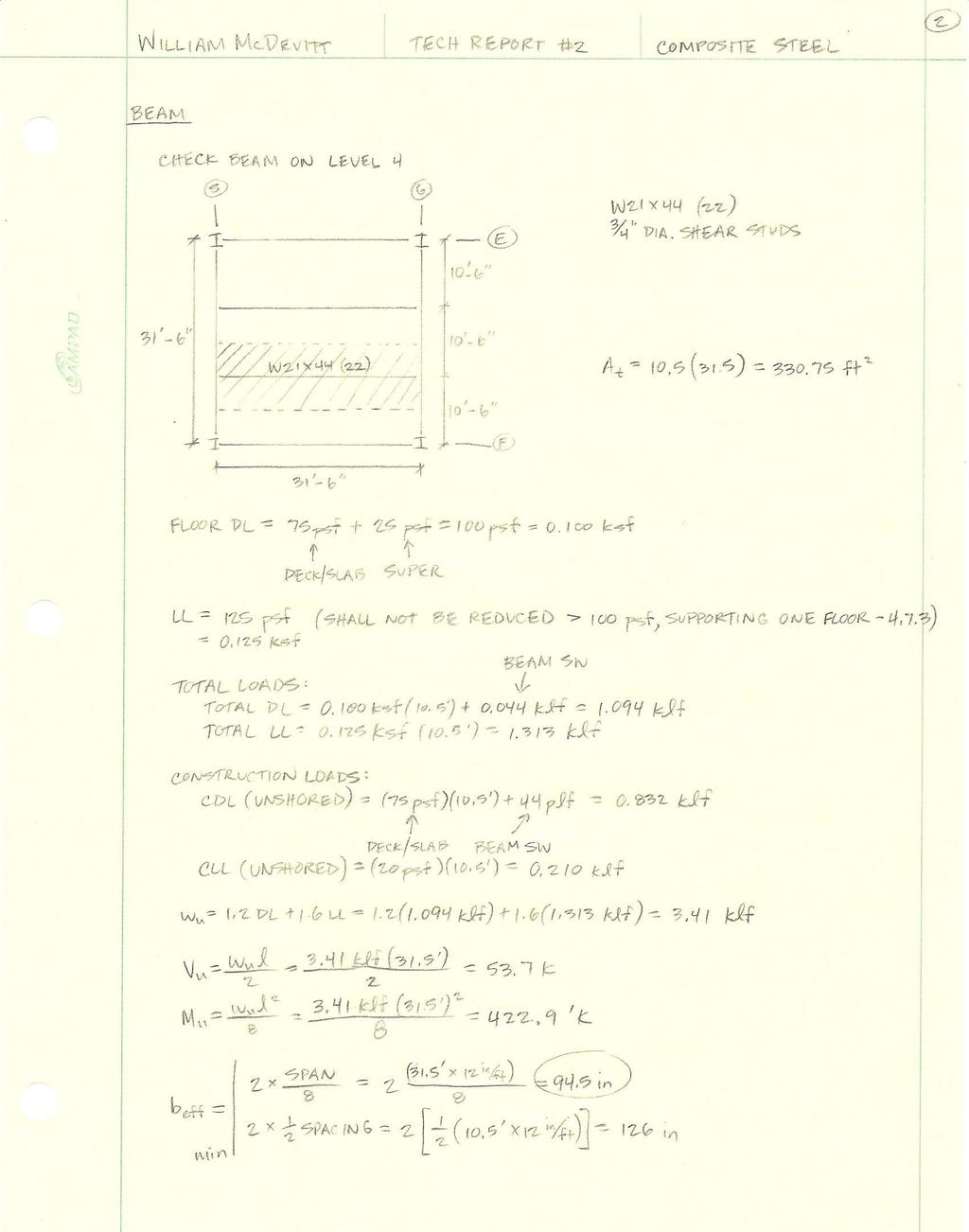
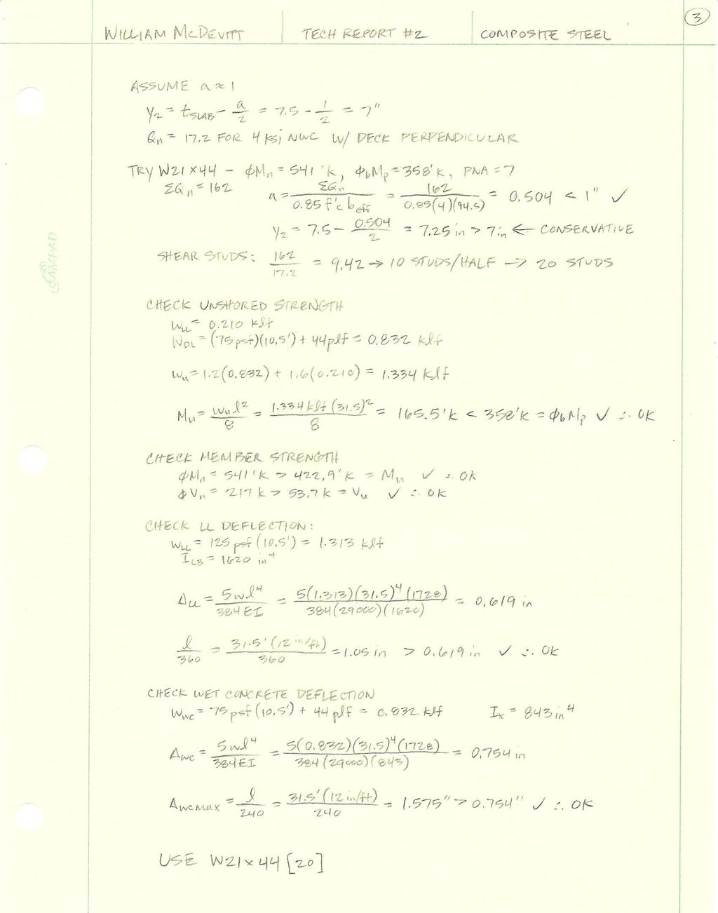
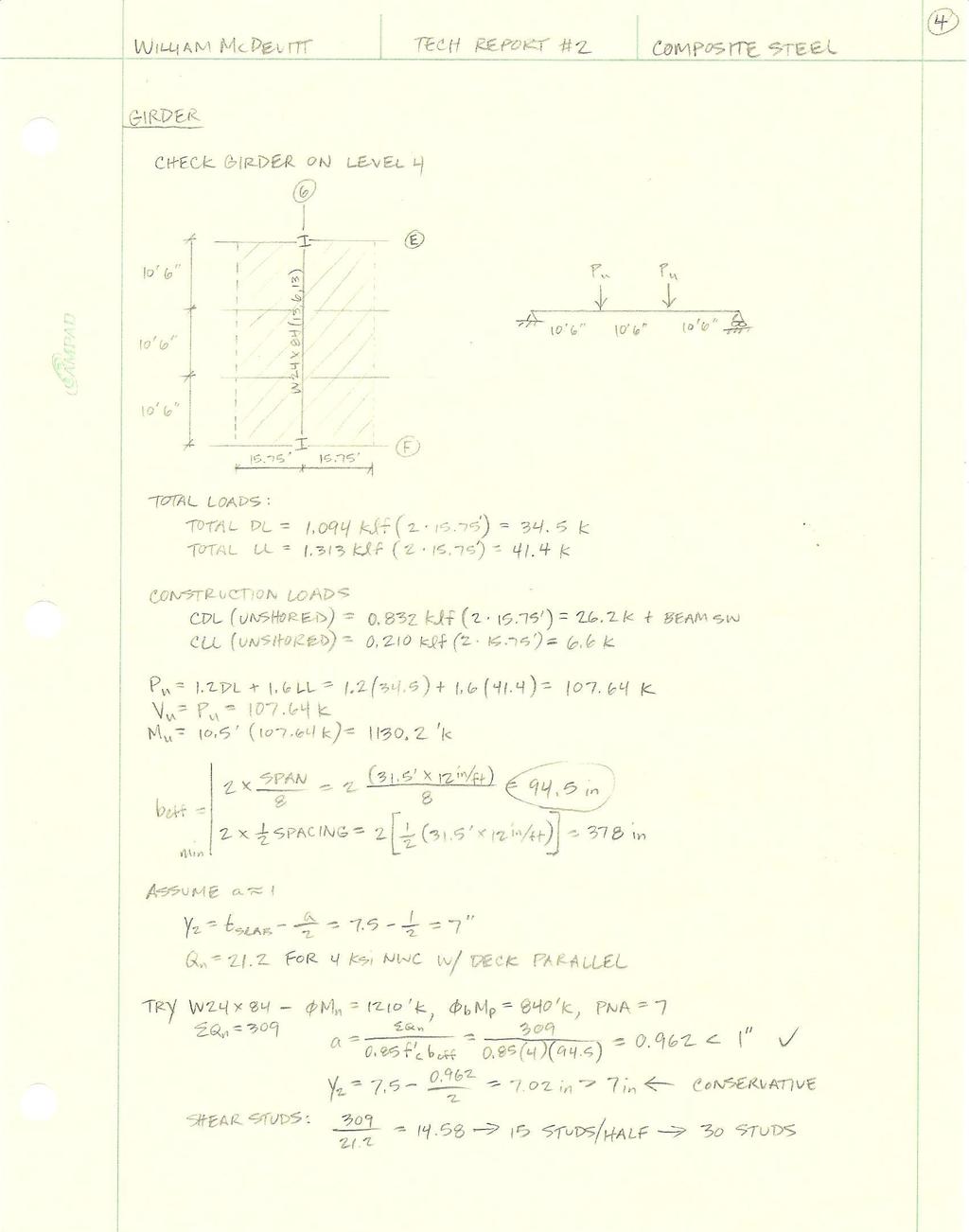
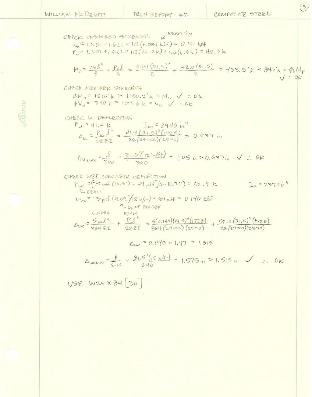
11 Existing Floor System Composite Steel Description Figure B Typical Bay on Level 4 (Cannon Design) The existing floor system for GHVI is composite steel with 31-6 by 31-6 bays and beams spaced at A typical bay on the fourth level was used for the analysis of this system, and is shown in Figure B. The structure utilizes a 3 composite metal deck with a total slab thickness of 7½. The metal deck is 18- gage galvanized steel and rests on W21x44 beams, which frame into two W24x84 girders. Shear studs are used on both the beams and girders in order to create composite action with the slab. Refer to Appendix B for the design of the existing floor framing system
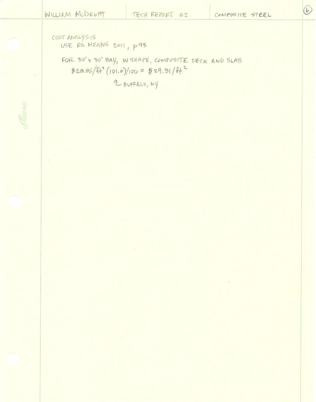
12 Design Criteria Figure C Typical Composite Steel Construction (Cannon Design) Bay Size = 31.5' x 31.5' Slab Thickness = 7.5" (Total) Normal Weight Concrete f' c = 3000 psi 18-Gage Galvanized Steel Deck Beams: 2 - W21x44 (20) Girders: 2 - W24x84 (30) 3/4" Shear Studs Cost = $29.31/ft 2 Advantages Reduced weight Shallow members Effective use of materials (concrete and steel) Good for long spans and heavy loads Easy and efficient to design Quick to construct Disadvantages Requires spray on fireproofing Medium lead time required for steel members Added cost of shear connectors
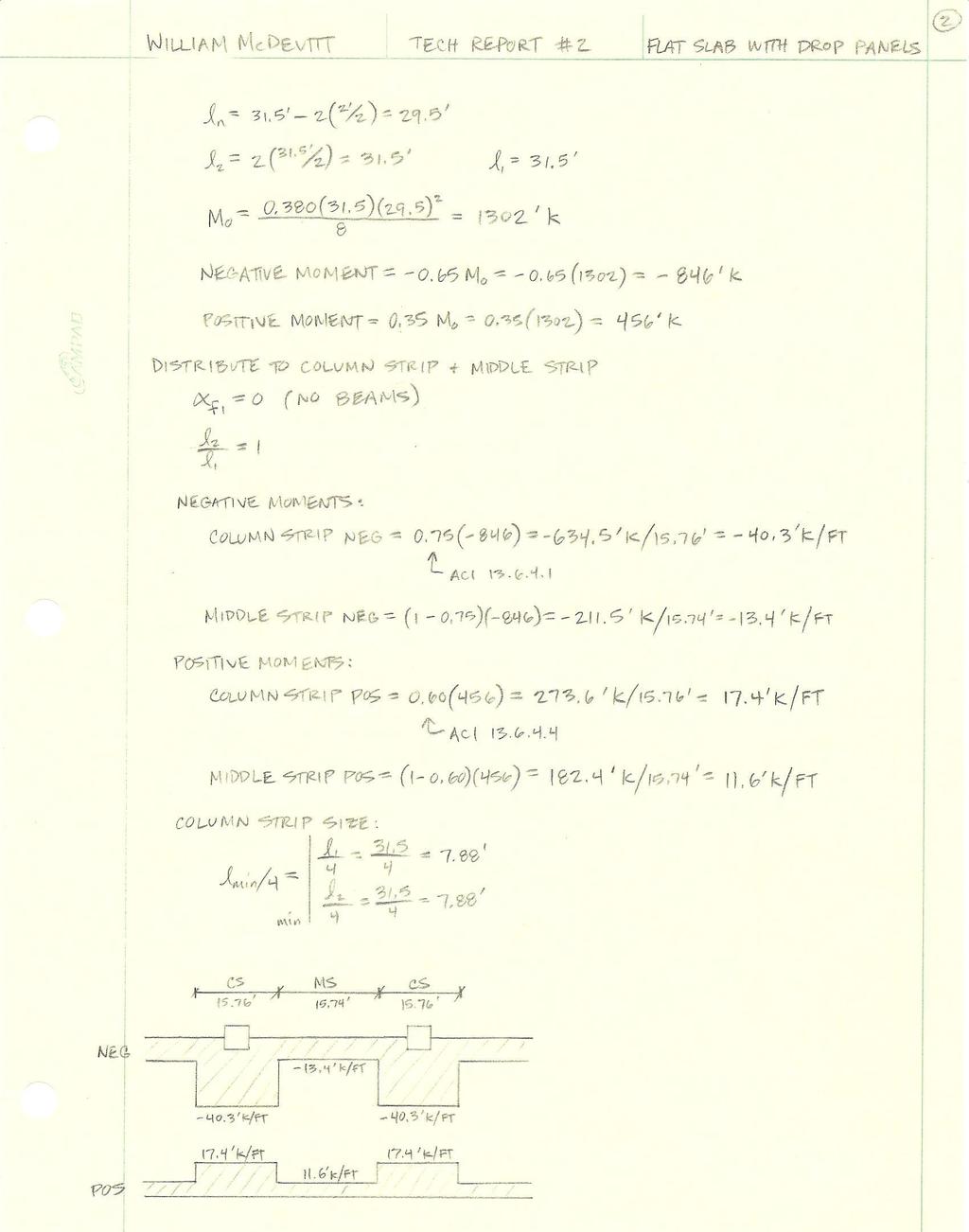
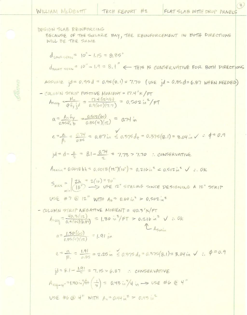
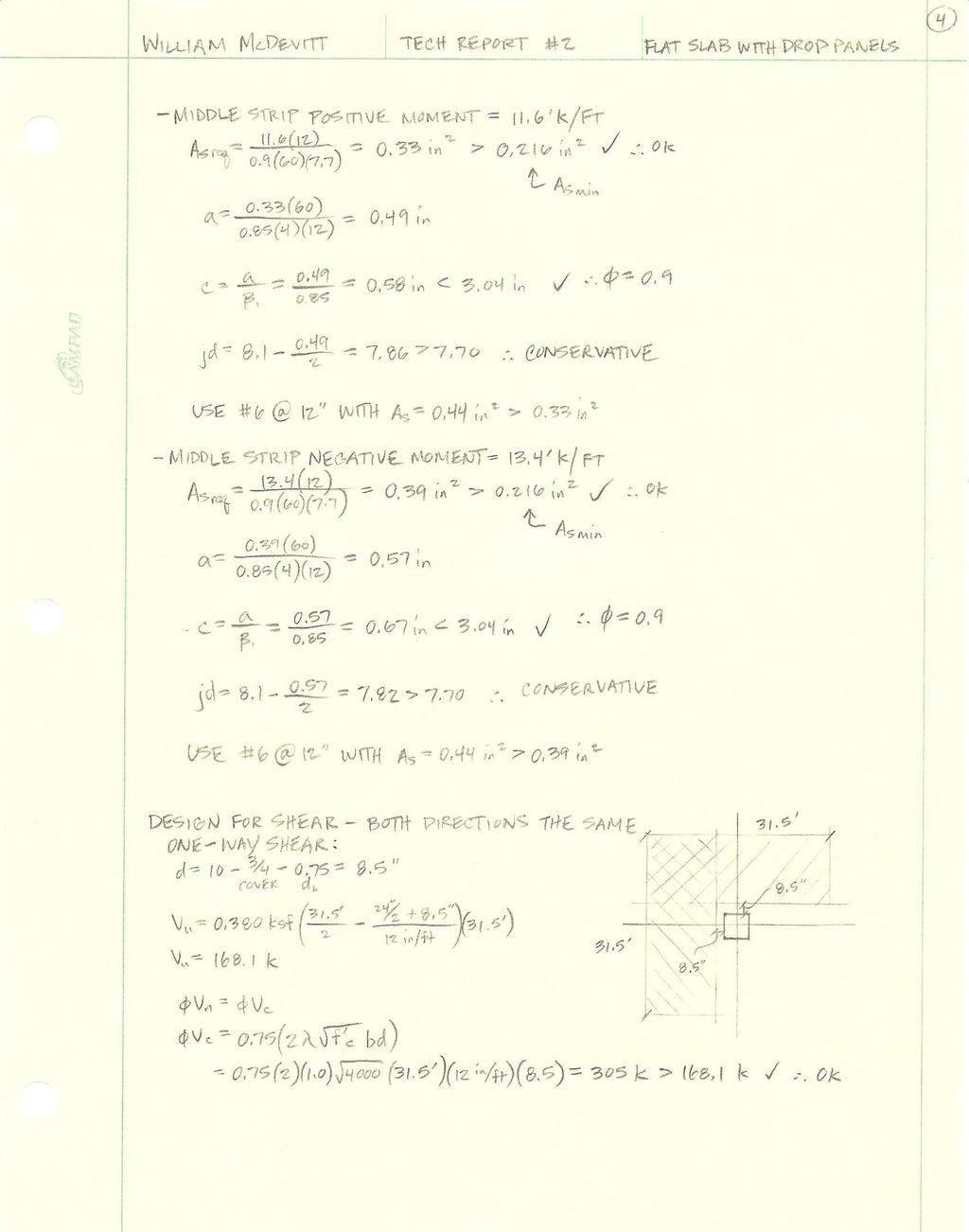
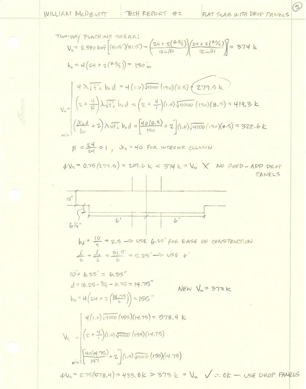
13 Alternative Floor System 1 Flat Slab with Drop Panels Description Figure D Typical Flat Slab with Drop Panels Bay The first alternate system to be designed was a two-way flat slap with drop panels. The design initially started with a flat plate system, under the assumption that drop panels would be needed due to the large live load on the slab. A slab thickness of 10 was chosen to meet ACI , and it was determined that the direct design method could be used to design the slab. The column strip and middle strip reinforcing was designed, and can be found in Appendix C. Finally, one-way shear and two-way punching shear was checked for the slab at the columns. It was determined that the column would indeed punch through the slab if drop panels were not implemented, and so drop panels were designed. When designing the drop panels, ease of constructability was considered, and so a drop of 6¼ was used. A detailed set of calculations for this system is located in Appendix C
14 Design Criteria Bay Size = 31.5' x 31.5' Slab Thickness = 10" Normal Weight Concrete f' c = 4000 psi Drop panel size = 12' x 12' Drop panel depth = 6.25" Cost = $18.03/ft 2 Advantages Increased shear strength at critical section around columns Simple construction and formwork Low floor-to-floor heights (not necessary for this building) Relatively flat ceiling Used for moderate to heavy live loads Disadvantages Increased self-weight Limited deflection control Future slab openings will be a problem with two-way reinforcing Possible lateral system redesign
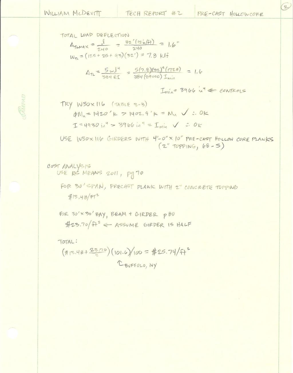
15 Alternative Floor System 2 Pre-Cast Hollow Core Plank Description Figure E Typical Pre-Cast Hollow Core Plank Bay The second alternative floor system designed for GHVI was a pre-cast hollow core plank system. Because the pre-cast planks come in 4 sections, the standard bay size of the building was altered from 31-6 by 31-6 to 32 by 32. This change is minimal, would be easy to implement, and would have a lower cost than ordering specially designed pre-cast planks. The PCI Design Handbook was used to size the planks, and it was found that 4-0 by 10 planks with 2 of topping would be sufficient. These planks would contain 6-8/16 diameter straight strands. Finally, these planks would rest on 2 W30x116 girders. A complete set of calculations for this system can be found in Appendix D. Design Criteria Bay Size = 32' x 32' 4' x 10" panels with 2" topping 6-8/16" f strands (straight) Slab Thickness = 10" Normal Weight Concrete f' c = 4000 psi Girders: 2 - W30x116 Cost = $25.74/ft
16 Advantages Reduced weight Reduced sound and heat transmission Flat ceilings Quick and simple construction Sustainable Disadvantages Slight adjustment of column grid Large girders needed for support Long lead time Not exactly level; leveling compound may be necessary
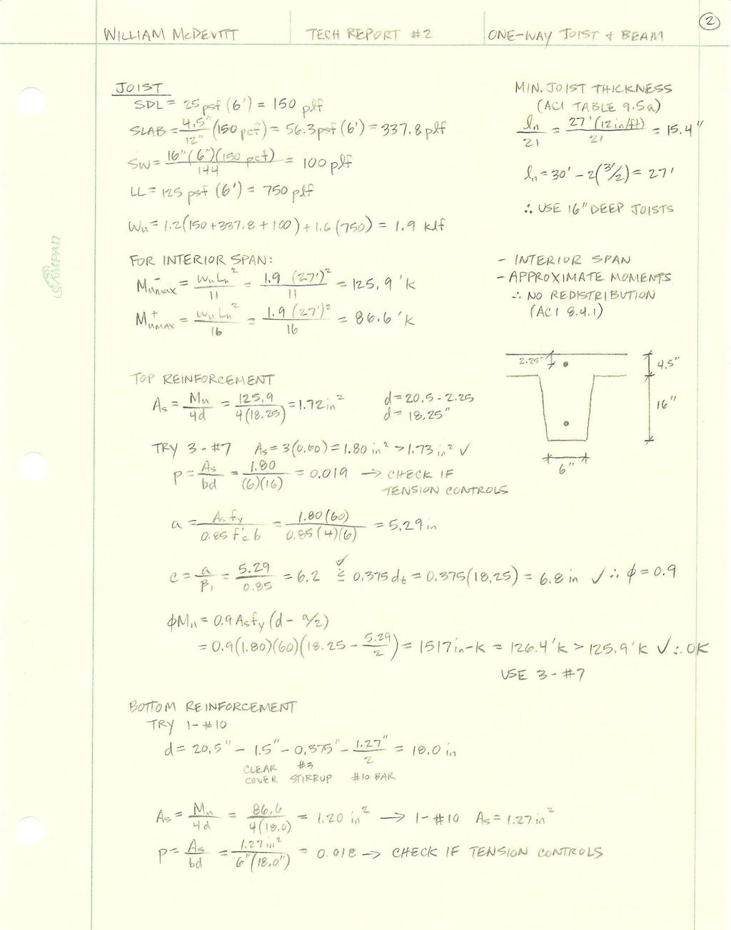
17 Alternative Floor System 3 One-Way Joist and Beam Description Figure F Typical One-Way Joist and Beam Bay The third and final alternative system designed for this building was a one-way pan joist and beam system. This system was considered because it is normally adequate for long spans and heavy live loads. A 4½ slab was selected to meet a two hour fire rating, and a 72 pan joist module was chosen. This module consists of 66 pans and 6 ribs as prescribed by ACI requirements. The ribs are 16 deep, making the total thickness 20½. Top and bottom reinforcement was sized, and shear was checked for an interior span. After the slab and joists were designed, the assumed girder width of 3 was checked and confirmed. Detailed calculations for the one-way joist and beam system can be found in Appendix E. Design Criteria Bay Size = 30' x 30' Slab Thickness = 4.5" 72" Pan module 66" Pan, 6" joist Normal Weight Concrete f' c = 4000 psi Girders: 3' wide Cost = $19.96/ft
18 Advantages Long spans Heavy live loads Wider column spacing Inherent vibration resistance Reduced self-weight due to joist voids Possible to fit mechanical equipment in joist voids Disadvantages Large self-weight, despite joist voids Adjustment of column grid More complex construction and formwork Possible lateral system redesign
19 Systems Comparison Composite Steel Flat Slab with Drop Panels System Pre-Cast Hollow Core Plank One-Way Joist and Beam Slab Thickness 7.5" 10" 10" 4.5" Total Structure Thickness 28.5" 16.25" 42" 20.5" Self-Weight 75 psf 125 psf 93 psf 73 psf Column Grid Impact N/A No Yes (minimal) Yes Fireproofing 2 hr (spray on) 2 hr 2 hr 2 hr Constructability Easy Medium Easy Difficult Lead Time Medium Short Long Short Cost $29.31/ft 2 $18.03/ft 2 $25.74/ft 2 $19.96/ft 2 Further Investigation? Yes Yes Yes Yes Table 1 Systems Comparison Structure Obviously, changing a major component of the structure, such as the floor system, will have an impact on the remainder of the building. The concrete systems are inherently heavier, and therefore would place a larger load on the building s foundation. The number of steel piles and the size of the pile caps may need to be reconsidered. Changing the diaphragm will also have an impact on the lateral system. Concrete systems will be stiffer and more capable of carrying the lateral load, but the current braced frame system would probably need to be redesigned when using the flat slab with drop panels or one-way joist and beam systems. Finally, deflection and vibration changes may need to be studied further. The composite steel system was checked and satisfies deflection requirements, and the concrete systems were designed to meet ACI minimum slab requirements. This ensures that the slabs will in fact meet deflection requirements, but if a specific comparison is to be made between all four systems, a more complex computer analysis will need to be conducted. Architecture Each alternative system was considered on how it would alter the architecture of the existing building. The flat slab system with drop panels would have very little impact. It would actually offer a slightly thinner floor thickness, and it would not be necessary to alter the column spacing in any way. The pre-cast hollow core plank system would have some impact on the buildings current architecture. This design would in fact require a minimal shift of the column spacing to allow for the placement of the 4 planks. It also requires very large girders to carry the load
20 of the planks, and therefore the floor thickness is much larger than the existing structure. Perhaps the most impact would be seen from the one-way joist and beam systems, which would require the column spacing to be altered by almost two feet. This may not have an effect on the aesthetic look of the building, but it could very well alter the layout of the floors. Fireproofing All of the systems considered in this study have a two hour fire rating as prescribed by code. The current composite steel design has an increased cost due to the need for spray on fire proofing. Each of the concrete systems would have inherent fireproofing due to the thickness of the concrete. Constructability Cost Constructability is a major concern when building a structure. The current composite steel system is easy to design and simple to construct, and so a change in the floor system would require a system just as simple. The flat slab system with drop panels would be a possibility under this requirement. Even though this system would call for the use of formwork, this formwork would be simple and easy to construct due to the nature of the flab slab. The pre-cast plank system is also extremely easy to construct. Each of the panels is fabricated off-site, transported to the site, and lifted in to place by a crane. The one-way joist and beam system would not be as easily constructed. This system requires complex formwork, which not only takes time, but costs more. The most important consideration when choosing a floor system may be cost. Table 1 above shows the cost per square foot for each of the systems analyzed. It can be seen that the current composite steel system is actually priced the highest. This may be due to the fact that it requires a large amount of concrete, as well as structural steel members and detailed connections. The pre-cast plank system has the second highest cost, and this is somewhat expected due to the fact that they are fabricated off-site and trucked where they are needed. The two remaining concrete systems have similar prices, but for different reasons. Flat slab systems with drop panels need less formwork and labor, but require more cubic yards of concrete. The one-way joist and beam system will require less concrete, but has a need for complex formwork. While these estimates give a good comparison of the different prices, if the decision is to be made on cost alone, a more in-depth cost analysis should be completed to assure that the correct system is selected
21 Conclusion This second technical report has investigated three alternative floor systems for the Kaleida Health and University at Buffalo Global Heart and Vascular Institute. Analysis of a flat slab system with drop panels shows that this system is the most viable option for an alternative design. The flat slab system works well with moderate spans and heavy live loads; both of which are seen in GHVI. It would have a minimal impact on the architecture of the building, and would not alter the bay sizes. For this building, a flat slab system would be easy to construct, would contain the necessary two hour fireproofing, and would cost the least. The pre-cast hollow core plank system would also be a viable option. Although it would increase the floor depth considerably, and slightly alter the column bays, it would be easy to construct and would be fire-rated for two hours. This system would come at a higher cost than the other two alternative systems, but it would be less expensive than the current composite steel design. A one-way joist and beam design would be the most difficult system to construct, but it is the lightest and second least expensive system. This strategy would be a viable alternative, but it would be necessary to modify the column bays by almost two feet in each direction. After careful analysis of each of these systems, it can be concluded that all three are viable options, but that the flat slab system may be more efficient and cost effective for this building. Future computer analysis will be conducted to examine lateral and foundation designs, and a more specific cost breakdown may be necessary
22 Appendix

23 Appendix A: Typical Floor Plans and Elevations Figure G Site Plan (Cannon Design)
24 Figure H Typical floor framing plan (Cannon Design)

25 Figure I West elevation (Cannon Design)

26 Appendix B: Existing Floor System Composite Steel
27 - 27 -
28 - 28 -
29 - 29 -
30 - 30 -
31 - 31 -

32 Appendix C: Alternative Floor System 1 Flat Slab with Drop Panels
33 - 33 -
34 - 34 -
35 - 35 -
36 - 36 -

37 - 37 -

38 Appendix D: Alternative Floor System 2 Pre-Cast Hollow Core Plank
39 - 39 -

40 Appendix E: Alternative Floor System 3 One-Way Joist and Beam
41 - 41 -

42 - 42 -

43 - 43 -