Far-UK & Axon Automotive
|
|
|
- Ashlyn Boyd
- 5 years ago
- Views:
Transcription
1 Far-UK & Axon Automotive Modelling and Simulation
2 Contents About Us Engineering Overview Engineering Strategy Prediction, testing, correlation Case Study: Epsilon Electric Vehicle FEM Issues


3 Far UK and Axon Axon Automotive Completed 5 different cars based around Axontex Capabilities include Design and prototype full vehicles Full Finite Element Analysis of carbon fibre structures in crash, including VCA approval for large vehicle Currently working on a number of vehicle structures for OEM Far Composites Developing new composites processes for customers Capabilities include Strong research team with experience of developing new materials and applying them to products Strong focus on cost and quality Currently working on three new composites processes 3


4 The Evolution World s first carbon space-frame 2007 Axon Axon Far Platform Chassis Commercial applications 2014
5 Vehicle Structures and Components Lightweight up to 70% savings compared to steel Can be applied to complete structures and components Can be applied cost effectively Combination of carbon fibre with a range of materials e.g. aluminium, steel, glass fibre 5


6 Engineering Overview Axon are appraised by the VCA for coach rollover approval; LS-Dyna simulation to ECE R66 Occupant estimated mass predicted to increase suggesting coaches will need to reduce mass.


7 Full Vehicle Simulation FEA: Occupants LS-Dyna Testing: Assemblies Testing: Vehicle Crash Package Layout FEA: NASTRAN Freebody models, Internal loads/moments, stiffness, Cross-Section, joints Materials Selection, Testing: Coupons FEA: Crash Systems LS-Dyna Component Manufacture, Testing: Correlation FEA: Crash pulse LS-Dyna FEA: Laminate & Joint Strength Nastran
8 Full Vehicle Simulation Design for composite vehicle structures Decouple crash system from occupant cell Occupant cell to be strong (implicit solver) Crash structures to absorb energy (explicit solver) Ensure bonded joints don t fail
9 Engineering Overview Composite Body-in-Black approach Crash peak loads drive strength (ply failures) Inter-component stiffness minimise adhesive stresses (peel) This increases local and global stiffness When global structure working effectively together, then material usage can be minimised
10


11 Case Study Analysis setup Source: IKA Force curves obtained from LS-Dyna crash analyses Analysis results studied for Stress Strain Failure index Deformation Freebody forces/moments Local force peaks used in Nastran inertia relief analysis
12 Case Study Freebody results are pasted into spreadsheets and separated into Forces (Fx, Fy, Fz) Moments (Mx, My, Mz) Bending moment, shear force plots against beam location set beam crosssection. Beam cross-section converted to laminate plies for shell element model Chart Title 800, , , , , , , , , , , ,000, ODB1 ODB2 ODB3 ODB4 RW1 RW2 RW3 RW4 RI1 RI2 RI3 RI4 SI1 SI2 SI3 SI4 SP1 SP2 SP3 SP4 RO1 RO2 RO3 RO4


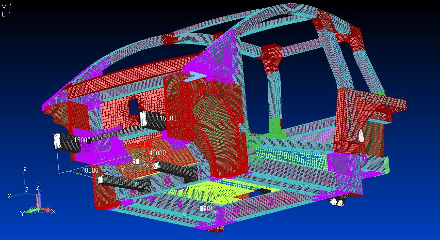
13 Case Study Vehicle Beams Beam elements Vehicle Equipment Beam elements, RBEs, Solids, Springs Vehicle Joints RBE elements Vehicle Panels Shell elements
14 FEM at Axon Far/Axon working on maintaining smaller models using less computing power Know what you are looking for and model for that Model what can be manufactured Prove local models using fine meshes Attempt to glean maximum info from beam element models
15 Current & Future Work Testing for correlation Adhesive bonds & Bonded joints Noise Vibration Harshness (components and vehicles) Materials Beams Optimisation Metallics for hybrid BiW structures Environmental & Thermal FEA Pattern thermal distortion for improved mould processing A-Class surface longevity Isogeometric Elements (LS-Dyna) Seamless modelling from CAD files
16 . Thank You