POWER-INSTALLED FOUNDATIONS, GUY-ANCHORS AND INSTALLING EQUIPMENT
|
|
|
- Rodger Reynolds
- 5 years ago
- Views:
Transcription

1 POWER-INSTALLED FOUNDATIONS, GUY-ANCHORS AND INSTALLING EQUIPMENT

2 D uring the past 35 years, Chance expertise and resources have perfected power-installed foundations and guy anchors supporting many utility structures. You know Chance as the World s foremost authority on earth anchoring. Now you can take advantage of Chance as the leading innovator in power-installed foundations for the utility industry. We encourage you to consult with us about your tower foundation and guy anchor requirements. Partner with Chance resources in the early stages of your project. Chance engineers will analyze your tower loads, soil conditions and construction methods. We ll then recommend the optimum tower foundation and guy anchor system. Give your Chance representative the load and soil information for your proposed transmission project so Chance foundation and anchor application engineers can conduct a comprehensive evaluation. Based upon the information provided, we will conduct a study and recommend the system best suited to your needs. It s a total civil construction package. Our service includes the foundations, the guy anchors and the guy grips...not to mention the experience and expertise to match the various parameters to the most economical system type. From choice of material to crew training, installing technique and torque requirements, Chance has a comprehensive plan you can count on. Choose Chance foundations and guy anchors for your transmission towers. They re field proven, field respected.


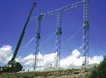
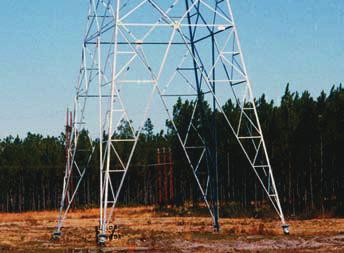
3 Tower support method that saves days and dollars C ompared to traditional ways of constructing transmission tower foundations, the Chance powerinstalled, screw-type foundation system offers attractive benefits in the conservation of labor, materials and equipment. And, most importantly, it saves time. Chance tower foundations for lattice steel, self-supporting structures usually install at the rate of two to three towers per crew day. Single-element foundations for guyed towers generally install at five or six per crew day, including guy anchor installation. If your rotary digging equipment provides adequate torque and down pressure, you can install Chance foundations. The only additional elements necessary are Chance Kelly-Bar adapters, torque indicator and drive tool. Chance foundations and guy anchors are installed in the same manner. You will save on labor costs because smaller work and fewer crafts are involved. Unlike concrete, Chance foundations and anchors can be scheduled throughout the year. Weather seldom stops construction. There is no waiting for concrete to cure, no excavation and no spoils removal. Towers can be erected immediately, so you save time and eliminate returns to the site. Chance foundations and anchors are ideal in areas inaccessible for conventional construction, or when weather limits construction time. They are valuable for rapidly restoring service in emergencies. You can install Chance foundations and anchors in almost any type of terrain, including steep inclines, flood plains, glacial till, sand, swamps and bogs. Once the foundations are in place, you can erect the tower using traditional construction practices. Weather will not delay your construction timetable. You can install Chance foundations in wet and freezing conditions as well as ideal weather. The design of Chance foundation systems adapt to site conditions. Your crews have many options available, should they encounter unusual or peculiar installation situations. 2

4 Designed for adaptability S implicity of design is one of the greatest advantages of the Chance foundation and anchor systems. The basic foundation and anchor element consists of a multi-helix lead section designed to withstand specific load torque. Extension sections can be added which help permit the lead section to be driven to the necessary depth. More than 35 years of research, engineering, product development and testing by Chance have brought the art of power-installed foundations and anchors to its mature state. Size and weight are no longer criteria for rating reliability. Advanced design, strength of steel and the science of soil mechanics combine to establish foundation and anchor dependability. Our foundations are designed to withstand the stress of torsion, bending and shear. High-strength steel helix plates distribute the up-lift and compression forces. The pipe shaft transfers horizontal shear, torsion and bending to surrounding soils. Guy anchors are designed to withstand the tensile loads of guyed towers. Soil data for your tower sites is entered into our geotechnical anchor data bank. Using proprietary software programs, Chance engineers then job-match each tower foundation and anchor to your specific soil condition to achieve predictable holding strength. You can rely upon Chance foundations and anchors to perform as designed. Based upon our years of combined experience serving the utility industry, we know how to get the materials you need on-site, on time and ready to use. 3
5 SOIL CLASSIFICATIONS Typical Blow Class Common Soil-Type Description Geological Soil Classification Probe Values Count N per in -lbs. (Nm) ASTM-D Solid hard rock, unweathered Granite, Basalt, Massive Limestone N.A. N.A. 1 Very dense and/or cemented sands; Caliche, (Nitrate-bearing gravel/rock) coarse gravel and cobbles (90-208) 2 Dense fine sand; very hard silts Basil till; boulder clay; caliche; and clays (may be preloaded) weathered laminated rock (78-98) 3 Dense clays, sands and gravel; Glacial till; weathered shales, schist, hard silts and clays gneiss and siltstone (65-78) 4 Medium dense sandy gravel; very Glacial till; hardpan; marls stiff to hard silts and clays (52-65) 5 Medium dense coarse sand and sandy Saprolites, residual soils gravels; stiff to very stiff silts and clays (39-52) 6 Loose to medium dense fine to coarse Dense hydraulic fill; sand; firm to stiff clays and silts compacted fill; residual soils (26-39) **7 Loose fine sand; Alluvium; loess; Flood plain soils; lake clays; soft-firm clays; varied clays; fill adobe; gumbo, fill (13-26) **8 Peat, organic silts; inundated silts, fly ash Miscellaneous fill, swamp marsh less than Class 1 soils are difficult to probe consistently and the ASTM blow count may be of questionable value. **It is advisable to install anchors deep enough, by the use of extensions, to penetrate a Class 5 to 6, underlying the Class 7 or 8 soils. SOIL TYPES The simplest way to classify soils is cohesive and non-cohesive. Fine grained soils such as clay are considered cohesive, while sand and other coarse grained soils are non-cohesive. The general headings of cohesive and non-cohesive soils may be further subdivided by several other characteristics such as origin, method of deposition and structure. Soil structure may be classified as deposited or residual. Deposited soils have been transported from their place of formation to anchor location. Residual soils are formed by physical and/or chemical forces breaking down parent rocks or soil to a more finely divided structure. Residual soils are sometimes referred to as weathered. Soil structure properties can be categorized into loose, dense honeycombed, flocculated, dispersed or composite. Unfortunately, these soils do not necessarily retain consistency at various depths. Often, they are in layers of different thickness of unlike soils. Anchoring problems are more complicated when a soft soil layer is sandwiched between two hard or dense layers. Under such circumstances, the relative position of an anchor helix in the soil matrix becomes critical. In these cases, assuming the helix remains rigid and the soil fails, the anchor begins to 4 creep. If the soil fails near the helix, it begins to flow around it. Successful, trouble-free anchoring demands the careful evaluation of local soil conditions and anchor types. With out proper soil/anchor planning, maximum anchor performance can never be assured. FROST, WATER AND SOIL Armed with knowledge of soil type or class, the potential effects of frost and water on soil and anchors can be evaluated. If an anchor helix is in a zone of deep frost penetration, frozen soil will behave as a stiffer soil and will generally yield greater holding capacity. However, when spring thaws begin, soil in the overlying zone will be water-saturated while the layer housing the helix will remain frozen. This condition is analogous to a hard layer under a soft layer, and may result in sudden anchor failure. Sometimes anchor jacking or movement out of the ground occurs during these conditions. In areas with permafrost, the helix should be at least three to five feet below the permafrost line, and provisions made to prevent solar energy from being conducted down the anchor. Anchor holding capacity decreases as moisture content increases. If a helix is installed at the water table level, anchor capacity should be determined based on the water table above the helix. Such a condition can reduce helix capacity by as much as 50 percent in granular soil. (A water table is usually defined as the elevation at which the water will stabilize in an open hole 24 hours after the hole is drilled.) Water, draining from fine grain soil under load, will permit creep. This is similar to the consolidation phenomenon under a foundation. Rapidly applied loads due to wind or ground tremors have little effect on creep so long as they do not exceed soil shear strength. However, line angle structures producing high normal loading can cause clay pore water to slowly drain off. Under such circumstances, creep could become troublesome even though the anchor/ soil system has not structurally failed. This results in the guy having to be periodically retensioned. EFFECTIVE ANCHORING The guiding principle to be used in selecting an anchor system is: FIELD CONDITIONS SHOULD DICTATE THE SYSTEM USED. The office solution, based on the best engineering analysis of the site, is subject to field changes. When a soil change occurs, one must consider how it affects the original solution. Steps must then be taken to compensate for differences due to changes.
. in the order of 2000 pounds (907 kg).")


6 DETERMINING ANCHOR-HOLDING-CAPACITY Tabulated anchor holding capacities of earth anchors are the result of field tests in different soils as defined by recognized soil investigation procedures. All data is recorded on Engineering Test Report Sheets (see below). in the order of 2000 pounds (907 kg). The load is slowly increased throughout the test with stops at increments of load for creep reading. Creep is read with the load stable and the anchor holding. During the anchor installation, care is taken to ensure regular practices are observed. If any special treatment is used, this is noted on the test data sheet. The anchor is pulled in line with the intended guy so the results represent the usable holding capacity on the guy. Creep* is measured in line with the pull after some initial load is applied to seat the anchor. The initial load is generally Using a transit, anchor creep is monitored as load is applied to the installed anchor. Chance has a full fleet of anchor testing equipment to help utilities plan their anchoring requirements. Engineering Test Report *Creep-measurement of a point on the anchor rod in relation to a fixed position on the ground and in line with the direction of pull. 5
 to which additional extensions of the same size diameter may be added if high lateral load-carrying capacity is not required.")

7 EXTENDIBLE-FOUNDATIONS F O R D E E P - B E A R I N G Chance extendible foundations come in two types. Type HS is a multi-helix lead section of 3-inch extra-heavy pipe shaft (7.6cm) to which additional extensions of the same size diameter may be added if high lateral load-carrying capacity is not required. Type TC is a similar-design lead section with the same type helices used on Type HS foundations plus extensions of 8-inch pipe (20.3cm) for resisting uplift, compression, bending and lateral loads. APPLICATIONS Extendible foundations are especially applicable in areas where a high water table exists. Concrete foundations require soil preparation prior to installation. On jobs with low working clearances, such as when underpinning an existing building, Chance extendible foundations are ideal. Light, temporary structures and prefabricated buildings also have been supported by foundations. Each foundation element may be incorporated into a reinforced-concrete grade beam beneath the structure, or the foundation may attach directly to metal beams which support a structure. In many instances, power-installed foundations can be in stalled using the same equipment used for drilled foundations. When encountering construction that demands low installing noise levels, vibration control, minimum spoils removal or ground-water concerns associated with excavation, look to removable and re-usable Chance power-installed foundations. 6