Water Management with Drainage Wrap System Page 1 of 9
|
|
|
- Baldric Howard
- 5 years ago
- Views:
Transcription
1 S410 energex Water Management with Drainage Wrap System Page 1 of DESCRIPTION A. Provide all labor, materials and equipment necessary to install the ENERGEX Water Management with Drainage Wrap system. The System consists of ENERGEX, approved Expanded Polystyrene Insulation Board, reinforcing fabric, ENERGEX base coat, Finish coat, Energex Waterproof Adhesive membrane and accessories as recommended by ENERGEX. B. Related work specified elsewhere: 1. Light gauge metals section Sheathing section Unit Masonry section Concrete section Sealants section C. Terms and Definitions: 1. ENERGEX Water Management with Drainage Wrap system Expanded Polystyrene (EPS) Board with an average density of 1.0 pcf, a flame spread rating of less than 25 and a smoke developed index of less than 450, and an R value of 3.85 per inch at 75 degrees F, must conform to ASTM C 578 Class A and be manufactured under a third party inspection program as approved by ENERGEX 2. ENERGEX insulation board must be a minimum of 3/4 in thickness, and is chamfered 1/2 on the bottom edge. The board rests in the PVC starter track to facilitate lateral drainage. 3. Secondary Weather Barrier: The secondary weather barrier over the approved wood substrate consists of a single layer of drainable building wrap in conjunction with a rubberized, self-sticking waterproof membrane Grade A or B for windows, doors, penetrations, outside & inside corners and for the termination of the system at the bottom edge of the wall. 4. Board Attachment: Energex approved/supplied mechanical fasteners are used to fasten the EPS Board to the substrate. See Detail for recommended fastening pattern, minimum one fastener per square foot of EPS insulation board. Before applying the Energex base coat, cover or spot fill each fastener depression with Base coat and let dry before applying base coat over entire surface of EPS board. 5. Reinforcing Fabric Balanced open weave fiberglass mesh, treated for compatibility with other materials of the system shall not be less than 4.3 oz (+/- 10%) per square yard Woodbridge Avenue Edison, New Jersey Office (888) Fax (718)
2 S410 energex Water Management with Drainage Wrap System Page 2 of 9 EIF systems are classified in accordance with their impact resistance per EIMA Standard Impact Standard Impact Resistance Medium Impact Resistance High Impact Resistance Ultra High Impact Resistance in-ibs in-ibs in-ibs Over 150 in-ibs standards are as listed below: High Impact Resistant System (Recommended for first floors, high traffic areas, and areas subject to abuse.) High Impact and Ultra High Impact requires incorporation of Energex Enermite 20oz Mesh prior to Energex standard mesh being installed. This system consists of an additional layer of Enermite (20 oz.) Mesh or Enermite (15 oz.) mesh embedded in Energex Base coat. The heavier mesh is always installed under the lighter mesh. In no case should the Enermite 20oz or 15oz mesh be used without the regular mesh (4.3 oz) as the final layer. 6. Base Coat - Provides the weather protection component of ENERGEX Water Management with Drainage Wrap system, by bonding the fiberglass mesh with the EPS Insulation. Any of the following base coats may be used: a) ENERGEX Enermix Dry Adhesive/Base Coat: Polymer modified base coat that only requires the addition of potable water at a rate of 1 1/2 to 2 gallons per 55 Lb. bag. b) ENERGEX Enermix Adhesive/Base Coat: Polymer based acrylic admixture that is blended with Type I or Type II Portland Cement in a 1:1 ratio by weight. c) ENERGEX Enermix Plus Base Coat: Polymer based admixture that is blended with Type I or Type II Portland Cement in a 1:1 ratio by weight. Thick Base Coat is utilized to achieve 1116 thickness in one pass. 7. Finish Coat - ENERGEX Finish functions as the decorative and protective textured weathering surface. ENERGEX Finish is manufactured in a variety of textures, colors and performance categories. 8. Accessories - Accessories such as PVC starter track, weep screed and expansion joints are to be used in conjunction with the ENERGEX Water Management with Drainage Wrap system Woodbridge Avenue Edison, New Jersey Office (888) Fax (718)
3 S410 energex Water Management with Drainage Wrap System Page 3 of QUALITY ASSURANCE A. Applicator Requirements 1. Application of the system must be by an applicator who has received instructions in ENERGEX application requirements and is acceptable to a ENERGEX manufacturer as a applicator in good standing. B. Approvals 1. The system shall be recognized for the intended use by the applicable building codes. C. Details 1. Conform with the ENERGEX current published suggested details and specific recommendations for the project SUBMITTALS A. The applicator shall submit evidence with the bid, that he has received instructions in ENERGEX application requirements and is acceptable to the ENERGEX manufacturer. The ENERGEX Water Management with Drainage Wrap system manufacturer will provide documentation of acceptance to the applicator. B. Samples 1. The applicator shall, before the project commences, provide the owner or the architect, a sample of suitable size of each color and texture as specified for the project for the purpose of obtaining approvals. 2. Each sample shall be prepared using the same tools and techniques as required for the actual application as to provide a benchmark for the installation. 3. An approved sample shall be available and maintained at the job site PRODUCT, DELIVERY, STORAGE AND HANDLING A. Deliver all material supplied by the manufacturer in original, unopened packages with legible manufacturer s identification and labels intact. B. Store all product supplied by ENERGEX manufacturer in a cool dry place, out of direct sunlight, protected from weather and other damage. In addition, the materials shall be stored in tightly sealed containers at a temperature of not less than 40 degrees F 2960 Woodbridge Avenue Edison, New Jersey Office (888) Fax (718)
4 S410 energex Water Management with Drainage Wrap System Page 4 of JOB CONDITIONS A. Weather and Environmental Conditions Application of the ENERGEX Water Management with Drainage Wrap system shall not take place during inclement weather unless appropriate protection is employed to protect all work. The system shall be protected during and after work ceases to insure full performance of the ENERGEX Water Management with Drainage Wrap system. Each temperature sensitive component shall be protected against freezing temperatures, high humidity, and rain or water splash for a period of at least 48 hours. The job should be tented and a heat source provided, if there is a projected drop in temperature below 40 degrees F during the first 24 hours after application of Base coat or Finish coat COORDINATION AND SCHEDULING A. The work in this section requires close coordination with related sections and trades. B. The parapets of all walls must immediately be protected to prevent water infiltration behind the system. The Cap flashing should be installed immediately after the Finish coat has been applied or provisions made for protection from backside water infiltration. C. ENERGEX approved sealant (where required) shall be installed in a timely manner MANUFACTURERS All products shall be obtained from ENERGEX, as manufacturer, or its approved supplier or distributor. Any substitutions must be approved in writing by the manufacturer MATERIALS A. Insulation Board Expanded Polystyrene (EPS Board) with an average density of 1.0 pcf, a flame spread rating of less than 25, a smoke developed index of less than 450 and an R value of 3.85 per inch at 75 degrees F. It must conform to ASTM C578, Class A and be manufactured under a third party inspection program approved by ENERGEX B. Weather Resistive Barrier The secondary weather barrier over the approved wood substrate consists of a single layer of Drainage building wrap, in conjunction with a rubberized, self-sticking waterproof membrane Grade A or B for windows, doors, penetrations, outside & inside corners and for the termination of the system at the bottom edge of the wall Woodbridge Avenue Edison, New Jersey Office (888) Fax (718)
5 S410 energex Water Management with Drainage Wrap System Page 5 of 9 C. Rubberized Waterproof Membrane Perimeter Flashing An approved rubberized, self adhering, waterproof membrane material provided by ENERGEX, or approved third party manufacturer. Minimum 40 mil thickness of Flexible Waterproof flashing required for all penetrations, windows, doors, protrusions and termination of Energex Water Management with Drainage Wrap system at starter track. D. Reinforcing Fabric 1. Balanced open weave fiberglass mesh, treated for compatibility with other system components. The fabric shall not be less than 4.3 oz. (+/- 10%) per square yard. EIF systems are classified in accordance with their impact resistance per EIMA : Standard Impact Resistance in-ibs Regular 4.3 oz. Mesh Medium Impact Resistance in-ibs Intermediate 5.3 to 12 oz Mesh High Impact Resistance in-ibs Light Armor plus Regular Mesh Ultra High Impact Resistance Over 150 in-ibs Armor Mesh plus Regular Mesh NOTE: By incorporating optional types, and weights of ENERGEX fiberglass mesh, varying degrees of impact resistance are obtainable. E. Base Coat - Any of the following may be used: a) ENERGEX Enermix Dry Adhesive/Base Coat: Polymer modified base coat that only requires the addition of potable water at a rate of 1 1/2 to 2 gallons per bag. b) ENERGEX Enermix Adhesive/Base Coat: Polymer based acrylic admixture that is blended with Type I or Type II Portland Cement in a 1:1 ratio by weight. c) ENERGEX Enermix Plus Base Coat: Polymer based admixture that is blended with Type I or Type II Portland Cement in a 1:1 ratio by weight. Thick Base Coat is utilized to achieve 1/16 or more thickness in one pass. F. Finish The Finish coat shall be one of ENERGEX S ready mixed, 100% acrylic polymer based Finishes as manufactured by a ENERGEX manufacturer. Specific colors, finishes and textures shall be indicated in drawings and approved by the architect or the owner Woodbridge Avenue Edison, New Jersey Office (888) Fax (718)
6 S410 energex Water Management with Drainage Wrap System Page 6 of 9 G. Accessories Components such as PVC Starter Track, Expansion Joint, and special duty mesh, that may be required and used in conjunction with the ENERGEX Water Management with Drainage Wrap system. H. Water - Shall be clean and potable SYSTEM PROPERTIES A. The system shall have been tested or qualified by the following test standards: R-value (resistance to heat flow), ft2 h F (m2 K/W) at 49 F (9 C) R-3.85 (0.68) R-3.85 (0.68) Full-scale multi-story, UBC 17-6 fire test with additions Complies with all Complies with all acceptance criteria acceptance criteria Wind driven rain, Federal Standard TT-C-555B No dampness No dampness on rear of panel on rear of panel Negative wind load resistance, ASTM E psf (7182 Pa) 150 psf (7182 Pa) Impact resistance, ASTM E72 Passes Passes Structural performance, ASTM E330 Negative presssure 195 psf (9337 Pa) Negative presssure 195 psf (9337 Pa) Positive pressure 175 psf (8379 Pa) Positive pressure 175 psf (8379 Pa) Tensile bond strength, ASTM D897 Concrete masonry psf (122,420 Pa), passed psf (122,420 Pa), passed Structural clay tile block 3298 psf (157,909 Pa), passed 3298 psf (157,909 Pa), passed Cement board 260 psf (12,449 Pa), passed 260 psf (12,449 Pa), passed Plaster 2600 psf (124,489 Pa), passed 2600 psf (124,489 Pa), passed Foam blocks 2727 psf (130,569 Pa), passed 2727 psf (130,569 Pa), passed Plywood sheathing 3001 psf (143,688 Pa) 3001 psf (143,688 Pa) Humidity resistance, Federal Test Method Standard 141, Method 6201 No change No change Accelerated weathering, ASTM G23 and ASTM G53 Passed 2000 hours Passed 2000 hours Water vapor transmission, ASTM E96 Exceeds requirements Exceeds requirements Salt spray/fog resistance, ASTM B hours, no deleterious effects 300 hours, no deleterious effects Toxicity, UPITT test Exceeds requirements Exceeds requirements Water penetration, ASTM E331 No water penetration on substrate plane Impact load, New York State Impact Load Test Complies with requirements Heat value, oxygen bomb specimen, UBC 17-2 (NFPA Std 259) 15, Btu/lb Heat of combustion, ASTM D ,894 BTu/lb No water penetration on substrate plane Complies with requirements 15, Btu/lb 17,894 BTu/lb 2960 Woodbridge Avenue Edison, New Jersey Office (888) Fax (718)
7 S410 energex Water Management with Drainage Wrap System Page 7 of 9 PART 3 - EXECUTION INSPECTION A. Project Inspection - Prior to work of this section, carefully inspect preparatory and installed work of other trades and verify that such work is completed to the point where this installation may properly proceed. B. Acceptable substrates for application of ENERGEX Water Management with Drainage Wrap system: 1. Exterior plywood, OSB board (type I, exterior), and other substrates (Dens Glass, Exterior Gypsum Sheathing) with prior approval from the manufacturer. The substrate shall have no planar irregularities greater than 114 inch. Notifications - The General Contractor and the Architect shall be advised of any discrepancies. Work shall not proceed until all unsatisfactory conditions are corrected and the substrate is acceptable, clean and free of any contaminants INSTALLATION A. Rubberized Flexible Waterproof Membrane Flashing is installed in the following locations, over the approved substrate, prior to windows or doors being installed: 1. Inside corners, outside corners, termination of system, at rim joist, window & door sills, jambs, headers, penetrations and construction openings. 2. Peel and stick the rubberized membrane to the substrate in a neat, flat and workmanlike manner. Noncorrosive staples can be incorporated for ease of application. A 6, 9 or 12 inch wide membrane is to be used, depending upon application. Minimum overlap of surfaces is Rubberized flexible membrane should overlap any adjacent surface or substrate a minimum of 2. All window and door jambs will receive a continuous wrap of the inside framing lumber, spliced and overlapped in the corners, where necessary. 4. Rubberized flexible membrane installed prior to the starter weep screed on at the bottom of the wood sheathing. Starter weep screed will be fastened onto, and the nails or screws will be through the membrane. B. The secondary weather barrier over the approved wood substrate consists of a single layer of drainable building wrap, in conjunction with a rubberized, self-sticking waterproof membrane Grade A or B for windows, doors, penetrations, outside & inside corners and for the termination of the system at the bottom edge of the wall. C. PVC Starter Track Weep Screed is nailed, or screwed onto, and through the bottom starter piece of the rubberized waterproof membrane. The Starter weep screed provides a straight, self draining track to protect the bottom edge of the EPS foam 2960 Woodbridge Avenue Edison, New Jersey Office (888) Fax (718)
8 S410 energex Water Management with Drainage Wrap System Page 8 of 9 D. Insulation Board is installed first at all doors, windows and protrusions. Butt all joints tightly to ensure a flat, flush and level surface. Use straight edge as needed to align EPS. Fill up all gaps and between boards with slivers of EPS or approved 1. Installation details at roof lines, windows, sills, and joints with other materials, refer to standard ENERGEX details in this manual. Window sills, parapets and tops of walls must have a slope of 4/12. For applications which do not meet 4112 requirement. PVC two part expansion joint must be installed on wood frame construction at the floor lines in multi-story construction. 2. Any irregularity of the insulation surfaces greater than 1/16 inch must be sanded flush, and the entire EPS surface will be rasped to ensure a flat, prepared surface. E. Base Coat and Reinforcing Fabric 1. Apply ENERGEX Enermix Adhesive/Base coat or Enermix Dry Base coat - Use a stainless steel trowel to apply Base coat to the entire surface of the insulation board. 2. Install Reinforcing Fabric Immediately place the reinforcing fabric against the wet Base coat and by troweling from the center to the edges, embed the fabric into the Base coat. The reinforcing fabric must be continuous, free of wrinkles and be fully embedded in the Base coat. The base coat shall show no sign of mesh color after drying. All corners and overlaps shall be at least 3 inches. Door, window and other openings, require additional butterfly strips of 8 x 12 regular reinforcing mesh embedded within the Base coat at a 45 degree angle at each corner during base coat application. See Detail. Allow at least 24 hours drying time. Additional time may be required at low temperatures or with high humidity conditions. Where shown on plans, the ENERGEX High Impact System is to be installed as follows: ENERGEX Enermite 15 or 20 oz Mesh is first embedded into the ENERGEX Base coat. The Base coat is allowed to dry for 24 hours. Then another coat of ENERGEX Base coat is applied over the first application to embed the regular reinforcing mesh as in D.2.a and D.2.b Woodbridge Avenue Edison, New Jersey Office (888) Fax (718)
9 S410 energex Water Management with Drainage Wrap System Page 9 of Finish Coat 1. Thoroughly mix the ENERGEX factory finish coat. Use a high speed mixer and stir until a uniform consistency is obtained. If necessary, add small amounts of clean, potable water (not to exceed 10 oz. per pail) to adjust workability. 2. Use Finish color and texture as it conforms to previously submitted and approved sample. 3. Use clean stainless steel trowels to apply Finish coat directly over the Base coat. (Some Finishes may be spray applied--please consult your ENERGEX manufacturer). 4. Special texture and grain effects are attained by troweling. Consistent troweling techniques by all mechanics on the job must be used to achieve uniformity of appearance. 5. Protect all work from inclement weather as per our printed guidelines for a period of 24 hours. 3.4 JOB SITE CLEAN-UP A. All excess ENERGEX wall system materials shall be removed from the job site by the ENERGEX Applicator. B. All surrounding areas where the ENERGEX system has been applied shall be left free of debris and foreign substances. END OF SECTION 2960 Woodbridge Avenue Edison, New Jersey Office (888) Fax (718)
10 WATER MANAGEMENT DRAINAGE WRAP SYSTEM SUGGESTED DETAILS
11 Energex Wall Systems NOTICE The suggested details which follow, also any related notes and/or text contained thereon are based upon typical requirements of ENERGEX Wa ll Systems exterior insulation and finish systems. These are published strictly as a guide for architectural and construction industry professionals in order to illustrate typical and/or general design conditions. Do not use these details by themselves. These details do not constitute design instructions for exterior insulation and finish applications. Use these details in conjunction with ENERGEX Wall Systems current product specifications, product data sheets and application instructions. Any details described are strictly for the purpose of illustrating typical system applications. Any other materials shown in any details are included only for the clarity of the system detail. These are incidental to the details. Please consult with the manufacturer s and/or suppliers of any separate material for their product specifications and application instructions. When site and/or design conditions not shown in these details are present, or if any unusual design is involved, and for a list of compatible sealant s, please consult with ENERGEX Wall Systems technical support for assistance. 2
12 CAUTION AND DISCLAIMER The following information should be obvious to design professionals, contractors, builders, installers, purchasers and users of Energex materials but please take a moment to review this information and to take an opportunity to remember the importance of sound design and construction practices, methods and mat erials.energex materials are components of construction assemblies and are not consumer products. Serious damage to Energex materials and to the buildings and building components and assemblies into which they are incorporated can result from (1) improper use, application or installation, (2) use as part of improperly designed or constructed assemblies or buildings or with defective adjacent materials or assemblies, (3) failure to follow applicable specifications, instructions and construction details, or (4) other design or construction defects, deficiencies and failures. Any resulting accumulation of water and moisture in wall assemblies may cause damage to building components including delamination of wall coverings Incorporating Energex materials, deterioration of internal wall components and mold. Energex sells its materials as is and disclaims all liability and warranties express or implied except for explicit limited written warranties issued to building owners in accordance with Energex approved warranty program offerings from time to time. Energex undertakes no responsibility for the quality of itsmaterials except as otherwise provided in its approved warranty program offerings. Energex assumes no responsibility that its materials will be fit for any particular purpose, except as otherwise pr ovided in Energex approved warranty program. Energex will not be liable for any direct, incidental, consequential, or indirect damages (including lost profits) arising out of use of its materials. Please note that some jurisdictions may not allow the exclusion of implied warranties, so some of the above exclusions may not apply to you. Energex component materials are intended for application by qualified installers as specified by qualified design professionals. Energex component materials shoul d be installed in accordance with written specifications, instructions, details and applicable code organization evaluation reports under supervision of qualified builders, general contractors, design professionals or independent inspectors. Please see the relevant guide. Although every effort is made to ensure that the information is timely and correct, it is provided solely as a guide to assist the designer, specifier, builder, general contractor and/or installer. The responsibility remains with the designer, specifier, builder, general contractor and/or installer to apply the information provided by Energex properly to specific installations. Energex component materials should be installed only using suitable design and construction methods and with non defective properly installed and constructed adjacent materials and assemblies. Performance of the completed building components into which Energex component materials have been installed should be verified by testing and inspection as appropria te, carried out only by qualified persons. It is the user responsibility and obligation to provide for such inspection and testing. Energex component materials are not designed or intended to be able to correct or prevent damage from faulty design or workmanship such as the absence or improper integration of flashing, nor are they designed or intended to correct or prevent damage from other defective components of construction that leak anywhere into the wall assembly. Flashing should always be integ rated with the cladding to direct water to the exterior, not into the wall assembly, particularly at potential leak sources. The design/construction professional must take material compatibility and construction sequencing into account when designing a building exterior. Flashings, windows, roofs, doors and other building penetration and termination locations and adjacent materials should be fully evaluated, properly selected and constructed to prevent water entry into building assemblies. The accumulat ion of moisture behind Energex component materials may result in building damage. Qualified design and construction professionals should strictly comply with specified procedures for mixing, application and integration to avoid causing or contributing t o potential water intrusion problems. Energex disclaims, and assumes no liability for on -site inspections, for improper application, assembly, installation or use of Energex materials or any assemblies into which they are incorporated, for incorporation as part of an improperly designed or constructed building, for the nonperformance of adjacent building components or assemblies, for all on -site construction activities (being beyond Energex control), or for any damage including water or moisture intrusion or delamination resulting in whole or in part because of any such occurrences. Before use, design professionals, owners and contractors should fully investigate Energex materials and assemblies into which they are to be incorporated to enable informed choices as to suitability for a particular project and proper design and implementation. Purchasers of Energex component materials should share this Caution and Disclaimer information with purchasers or owners of buildings into which Energex materials are incorporated. Copyright 2009, Energex LLC 3
13 Table of Contents GENERAL CONSTRUCTION SYSTEMCOMPONENTS FRAMED WALL ROUGH WINDOW FLASHING INSIDE CORNER OUTSIDE CORNER EXPANSION JOINTS EXPANSION JOINT INSIDE CORNER/DISSIMILAR SUB STRATES THRU-SYSTEM FLASHING WITH WEEPS TERMINATIONS ABOVE PAVEMENT ABOVE GRADE VERTICAL BALCONY DECK WINDOWS HEAD ASSEMBLY (WINDOWS,DOORS,LOUVERS, ETC.) HEAD TERMINATION BACK WRAPPED JAMB BACKWRAPPED SILL ROOF LINE TERMINATION AT SOLID SOFFIT TERMINATION AT INSULATED SOFFIT CORNICE MEETS SYSTEM WALL PARAPET HIGH WALL AT LOW ROOF PENETRATIONS HOSE BIB SMALL ELECTRICAL FIXTURE FIXTURE ATTACHMENT SCUPPER TERMINATION AT APPLIANCE AESTHETICS GROOVE/REVEAL SMALL BAND/PROJECTION
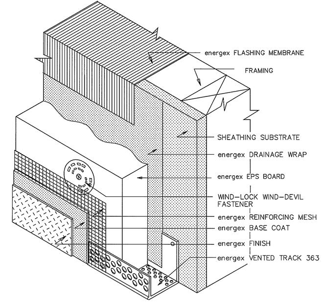
14 SYSTEM COMPONENTS 5
15 FRAMED WALL 6

16 ROUGH WINDOW FLASHING PART 1 7
17 ROUGH WINDOW FLASHING PART 2 8

18 INSIDE CORNER 9

19 OUTSIDE CORNER 10
20 EXPANSION JOINT 11
21 INSIDE CORNER/ DISSIMILAR SUBSTRATES 12
22 THRU-SYSTEM FLASHING WITH WEEPS 13
23 TERMINATION ABOVE PAVEMENT 14
24 TERMINATION ABOVE GRADE 15
25 TERMINATION AT VERTICAL EDGE 16
26 TERMINATION AT BALCONY DECK 17
27 HEAD ASSEMBLY(WINDOWS, DOORS, LOUVERS, ET AL.) 18
28 HEAD TERMINATION 19
29 BACK WRAPPED JAMB 20
30 BACK WRAPPED SILL 21
31 TERMINATION AT SOLID SOFFIT 22
32 TERMINATION AT INSULATED SOFFIT 23
33 CORNICE MEETS SYSTEM WALL PART A 24
34 CORNICE MEETS SYSTEM WALL PART B 25
35 PARAPET 26
36 HI GH WALL AT LOW ROOF 27
37 HOSE BIB 28
38 SMALL ELECTRICAL FIXTURE 29
39 FIXTURE ATTACHMENT 30
40 SCUPPER 31
41 TERMINATION AT APPLIANCE 32
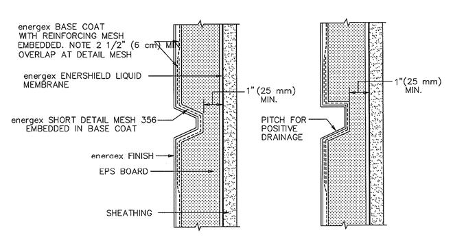
42 GROOVE/REVEAL 33
43 SMALL BAND/PROJECTION 34