TECHNICAL MEMORANDUM
|
|
|
- Reynard Kelley
- 5 years ago
- Views:
Transcription

1 TECHNICAL MEMORANDUM Project Name: Finish Water Pump Station (FWPS) Date: October 15, 2015 Client: City of Vallejo Project Number: 07784B.10 Prepared By: Reviewed By: Subject: Crystal Starr, P.E. Mike Dadik, S.E.; Peter von Bucher, P.E. TM 2 - Seismic Assessment 1.0 PURPOSE A preliminary seismic evaluation was conducted for the Finished Water Pump Station (FWPS) for the City of Vallejo in accordance with the Seismic Evaluation and Retrofit of Existing Buildings, ASCE which is referenced by the California Building Code (CBC) As part of the evaluation, a site visit was conducted on June 29, The purpose of this Project Memorandum is to summarize findings from Tier 1 Seismic Evaluation screening procedures of ASCE for the pump station with some Tier 2 quick checks, and provide budgetary construction cost estimates for the retrofit recommendations. The retrofit recommendations include: Roof anchorage strengthening. Replacing a portion of the floor slab and tying into the wall footings. Elastomeric lining over the floor slab. (Optional) 2.0 BACKGROUND There are three tiers of seismic evaluation and acceptance in accordance with ASCE The three tiers consist of the following: Tier 1 screening procedures - basic screening tier where a building is screened for deficiencies using checklists. Tier 2 deficiency-based evaluation procedures - further evaluation of any deficiencies identified in the Tier 1 screening. Tier 3 systematic evaluation procedures - evaluation of the entire building in a rigorous manner. Tier 3 evaluations are selected when a building has significant seismic deficiencies. pw:\\carollo/documents\client/ca/vallejo/7784b10/deliverables/seismic Assessment TM\Preliminary Seismic Evaluation Memo.docx 1
2 TECHNICAL MEMORANDUM 2 Based on a cursory review of the building plans available and a field investigation, Carollo determined that a Tier 1 and Tier 2 seismic evaluation is most suitable. A Tier 3 evaluation can be performed but would require an extensive analysis and greater expense to the Owner. Since minimal documentation on the building is available, data collection and materials testing would be required to evaluate the building components in accordance with a Tier 3 evaluation. Tier 1 and 2 evaluations can utilize default materials properties based on historical data. 3.0 ANALYSIS A Basic Performance Objective for Existing Buildings (BPOE) must be specified in accordance with ASCE The BPOE is defined as the performance objective based on the acceptable extent of damage to the building in a specified earthquake ground motion. Each Building Performance Level correlates to a Risk Category as used in the California Building Code (CBC) for new building design. The FWPS was evaluated at an Immediate Occupancy BPOE. This is the equivalent performance objective to a Risk Category IV for an essential facility in accordance with the CBC As defined in ASCE 41-13, the Immediate Occupancy BPOE is the post-earthquake damage state in which a structure remains safe to occupy and essentially retains its preearthquake strength and stiffness. Tier 1 checklists were completed after the visual screening site visit. The checklists evaluate the compliance of the Structural and Non-structural components of the building based on the criteria in ASCE Items that were identified as noncompliant and deficient would require a mitigating measure in accordance with Tier 2 procedures. The findings summarized below will identify those deficiencies and the suggested structural modifications. 4.0 LIMITATIONS The limitations of this evaluation are the absence of a geotechnical investigation for the site at the time of evaluation. A geotechnical investigation is recommended and the results of the investigation will be utilized in the final design. While no change in these conclusions is expected, if the soil pressures on the footings are found to overstress the footings, additional strengthening of the foundation may be required. 5.0 FINDINGS 5.1 Roof Anchorage Strengthening The current roof girders to wall connections consist of two 3/4-inch diameter bolts with minimal edge distance. Using the Quick Check procedures of ASCE 41-13, the anchors are structurally inadequate and unable to support the seismic wall anchorage forces calculated. pw:\\carollo/documents\client/ca/vallejo/7784b10/deliverables/seismic Assessment TM\Preliminary Seismic Evaluation Memo.docx 2
3 TECHNICAL MEMORANDUM 2 To increase the anchorage capacity at the connection, it is suggested that a bent plate be added below the existing girder to wall connection. The bent plate would be anchored to the interior face of the CMU wall with adhesive anchors, and welded to the bottom flange of the existing girders (Appendix C). It was observed that the exterior face shell at a roof to wall connection was cracked. However, with the new bent plate connection, the load would not get transferred through the top course of the masonry. It is recommended to repair the top shell cracking in the masonry to prevent the shell pieces from dislodging. 5.2 Replace a Portion of the Floor Slab The existing concrete floor slab is not tied into the concrete footings. The concrete footings extend down below grade as deep as 12 feet. The loading on the wall footings are significant at the Southwest corner of the building where the outside grade is lowest. This introduces more load on the footing because of the difference in soil pressures on each side of the footing. Based on preliminary calculations, the existing wall footing should be tied into the floor slab. This would be best accommodated by replacing a portion of the floor slab and doweling it into the remainder of the existing slab and the existing wall footing (refer to Appendix C). When demolishing the existing slab, the existing rebar can remain in place at the edges of the new slab to develop the reinforcement through the joint. The floor slab area to be replaced would require minimal relocation of equipment in the Southwest corner of the building. These findings are based on assumed lateral earth pressures and will be verified when geotechnical information becomes available. It is possible that the wall footings may not need to be tied into the existing floor slab or that further reinforcement may be required. 5.3 Floor Lining Cracks are present throughout the concrete floor which is evidenced by several 45 degree cracks starting at the corner of the pump pads (Appendix A, Photo 4). Filling the cracks with a polyurethane sealant followed by coating the entire slab with a high-solids epoxy would seal the cracks and improve the aesthetics of the floor slab. The cracks in the slab are non-structural issues, and do not necessitate a repair to provide seismic or structural performance. There are alternative coating systems such as thin-film epoxies that can be used at lower cost for applications that experience minimal foot traffic. A high-solids epoxy is used for cost estimating purposes below. 5.4 Roof diaphragm and Girders The existing diagonally sheathed wood roof diaphragm and steel girders appear in good condition. A portion of the roof diaphragm was replaced in kind recently due to a fire in the building. pw:\\carollo/documents\client/ca/vallejo/7784b10/deliverables/seismic Assessment TM\Preliminary Seismic Evaluation Memo.docx 3
4 TECHNICAL MEMORANDUM Pump Pads The existing isolated concrete pump pads appear in acceptable condition with no visible cracks. The pump pads have sufficient confinement reinforcement to control the potential for cracking. The 5-feet deep isolated pump pad transfers all vibration loads down into the foundation below without transferring loads into the floor slab and structure. The pump pad is likely of sufficient size to support a new horizontal pump. This would need to be verified and vibration resonance must be considered. 6.0 RECOMMENDATIONS The recommendations are listed in the table below with associated cost estimates. 6.1 Cost Estimate Budgetary construction cost estimates for the recommended retrofits are shown in Table 1. The general approach to estimating project costs is described in the PDR. Table 1 Item Recommended Retrofit Budgetary Construction Cost Estimates Finish Water Pump Station Electrification Project City of Vallejo Cost Concrete demolition/subgrade Preparation $12,000 New concrete slab with dowels $12,000 Roof anchorage $32,000 Floor lining and Crack sealant (Optional) $45,000 Combined Markups (70.9%) $72,000 Total Cost $173,000 pw:\\carollo/documents\client/ca/vallejo/7784b10/deliverables/seismic Assessment TM\Preliminary Seismic Evaluation Memo.docx 4
5 APPENDIX A PHOTOS pw:\\carollo/documents\client/ca/vallejo/7784b10/deliverables/seismic Assessment TM\Preliminary Seismic Evaluation Memo.docx
6


7 Photo 1: East Side of the Pump Station Photo 2: North Face of the Building pw:\\carollo/documents\client/ca/vallejo/7784b10/deliverables/seismic Assessment TM\Preliminary Seismic Evaluation Memo.docx 1

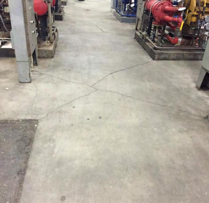
8 TECHNICAL MEMORANDUM 2 Photo 3: Face Shell Crack at Roof Connection Photo 4: Floor Slab Cracks pw:\\carollo/documents\client/ca/vallejo/7784b10/deliverables/seismic Assessment TM\Preliminary Seismic Evaluation Memo.docx 2

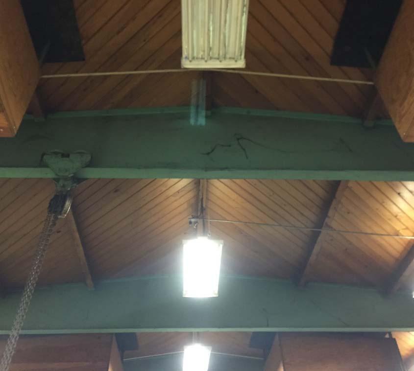
9 TECHNICAL MEMORANDUM 2 Photo 5: Pump Pads Photo 6: Steel Girders and Wood Diaphragm pw:\\carollo/documents\client/ca/vallejo/7784b10/deliverables/seismic Assessment TM\Preliminary Seismic Evaluation Memo.docx 3

10 TECHNICAL MEMORANDUM 2 Photo 7: Roof Replaced After a Recent Fire pw:\\carollo/documents\client/ca/vallejo/7784b10/deliverables/seismic Assessment TM\Preliminary Seismic Evaluation Memo.docx 4
11 APPENDIX B TIER 1 CHECKLISTS pw:\\carollo/documents\client/ca/vallejo/7784b10/deliverables/seismic Assessment TM\Preliminary Seismic Evaluation Memo.docx
12

13


14
15
16
17

18

19
20
21 TECHNICAL MEMORANDUM 2 APPENDIX C SUMMARY OF FINDINGS DETAILS pw:\\carollo/documents\client/ca/vallejo/7784b10/deliverables/seismic Assessment TM\Preliminary Seismic Evaluation Memo.docx


22 Replace slab. Expose existing rebar for lap A Drilled and adhesive bonded dowels along walls


23 1 Location of crack at exterior roof face shell

24
25