0160 Series Curtain Fire Dampers
|
|
|
- Anis Ann McCoy
- 5 years ago
- Views:
Transcription


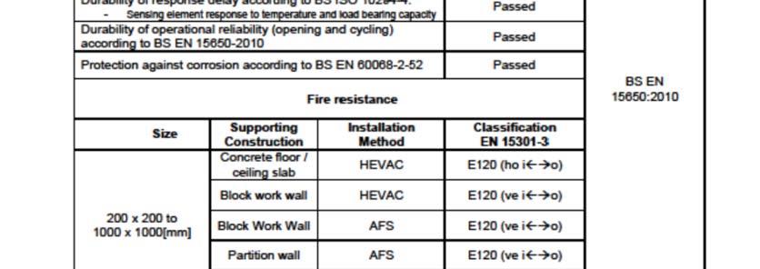
1 Burrell Way, General Description The 0160 series curtain fire dampers are designed to stop the spread of fire through ductwork, walls and floors in ventilation systems. When the fusible link reaches elevated temperature, it releases interlocking blades closing the damper by locking into the blade ramp sealing the damper closed. With the introduction of Construction Product Regulation on the 1st July 2013 all fire dampers are required to meet the product standard BS EN To achieve this standard the damper has to be tested to BS EN dynamic fire test. The dampers are then classified to BS EN that clearly states the integrity of the damper also in the way that damper was installed in the furnace. The standard also now included testing of fusible link to ISO that comprises of a dynamic release and holding tests. The biggest change in the current Building regulations Part B and Section 7 and the CPR is fire dampers have to be CE marked and that the dampers must be installed as tested. The maximum single section unit tested was 1000mm x 1000mm for both the HEVAC and AFS frame. Sizes above the maximum will be supplied as multi-section and are not CE labelled due to the current issues with the extended fields of application that we will shortly have an answer on. (PATENT PENDING) Construction Product Regulation To meet the requirements of the Construction Products Regulation 1st July 2013 Advanced Air fire dampers meet the requirements of the Product Standard BS EN with a classification under BS EN as stated in our Declaration Of Performance that has been assessed by the notified certification body BRE who have issued a Certificate of Consistency of Performance No: 0832-CPR- P0004. Installation Damper/Model Classification Blockwork Wall Drywall Blockwork Wall 0160-Standard Fire Damper 0160-Standard Fire Damper Motorised Fire Dampers E120 (ve i< >o) E120 (ve i< >o) E120 (ve i< >o) s Drywall Motorised Fire Dampers E120 (ve i< >o) s 1

2 Burrell Way, 2
3 Burrell Way, Product Details Blades: Casing: Springs: Ramps: Fusible Link: Performance: Further Options: Note: Material: 0.8 mm galvanised mild steel Spigot Length: 50mm Case length: 180mm Material: 1.2mm galvanised mild steel. Constant force springs made from heat treated stainless steel coil. 1.2 mm galvanised mild steel. 1.0 mm Brass soldered for release at 72 C 0/+2. Easy Maintenance Link for easy testing and reset Damper suitable for low, medium and high velocity casing (ductwork) leakage. Spigotted Type Class C DW144 Easy maintenance link (EML) Release Mechanism Visual Positioner Indicator (VPI) Micro switches Size limitations apply to some options, refer to chart New AFS installation for Blockwork and Drywalls - (PATENT PENDING) For Blockwork walls we had to ensure there was no added cost to the installation. The unit design allowed the fixing bracket to be on one side. In testing the drop rods were connected to a bracket attached directly to the wall therefore offering a simple low cost site installation For drywall installation both options are available, drop rods positioned within the wall & drop rods positioned outside the wall with the fixing to the AFS brackets, which have been successfully tested to BS EN Fire Damper Testing Details Test House & Test Fire Test Integrity Classification BS EN Warrington No: Effectis No: R0345a 0160 HEVAC Frame In Blockwork Wall Efectis - No. R0169a, R0169d 0160 HEVAC Frame In Floor Effectis No: R0320a, R0320b 0160 AFS in Blockwork Wall Effectis No: R0279a, R0279b 0160 AFS in Plasterboard Effectis No:R0319a, R0319b 0160 AFS in Plasterboard BS EN min E120 (ve i o) BS EN min E120 (ho i o) BS EN min E120 (ve i o) BS EN min E60 (ve i o) BS EN min E120 (ve i o) 3
4 Burrell Way, Sizing Information 0160 Damper With Rectangular Spigot & AFS Hanging System Note; Access Side Is Defined As The Side That Permits Testing & Resetting Of The Damper (Without The Need For Pull Rings To Unlock The Blade Pack) - Sizing Information 0160 Damper With Rectangular Spigot & HEVAC/HVCA Installation Frame 4
5 Burrell Way, Minimum and Maximum Dimensions Accessories Min & Max Dimensions Weights 1. The nett weights above are relevant to dampers using AFS hanging system. 2. Where a HEVAC/HVCA installation frame is included, a multiplier of 1.5 should be utilised. Date Issue Spec. No. 13/01/15 Rev 4 CE FD Sub Page No. 5


6 Burrell Way, Installation & Maintenance Instructions HEVAC Wall Installation - E120 Pre Installation Notes 1. Ensure that the damper is kept in a clean dry environment and that there is no damage to the damper. 2. Remove all packaging and transit ties before installation. Installation Procedure 1. Vertical builders work barrier to have an appropriately sized lintel to ensure an opening clearance for the expansion frame. 2. The opening in the wall must be cleaned, free of dust and any other contaminants which could impair the mortar adhesion. A clearance gap 25mm (min) to 50mm (max) must be maintained around the expansion frame of the fire damper (barrier contractor). 3. The damper shall be fitted centrally in the wall opening. 4. The tabs on the factory fitted galvanized steel expansion frame shall be bent out to tie the damper into the wall with the penetration seal. 5. The Penetration Seal must have a structural and fire rated compatibility with both the barrier and the damper and have sufficient strength to retain the fire damper within the wall in a fire situation. (4:1 Mortar Mix). 6. The Mortar Mix will be applied up to the installation frame face, take care not to leave any air pockets in the mix. 7. The ductwork connecting to the damper spigots must overlap by 40mm, leaving a 10mm clearance for any duct expansion in a fire situation. 8. All ductwork connections must be sealed with an approved ductwork sealer, and fixed with low resistance fixings such as: aluminium alloy rivets or nylon bolts. 9. All connecting ductwork must be independently supported within 1meter of the connections. 10. An Access cover should be fitted on the appropriate side of the barrier to enable inspections and maintenance work. Maintenance Procedure These dampers are installed as a life-safe product and will require regular physical and visual examinations. It is essential that that the assembly is kept in a clean, dust free condition at all times. It is essential that an access door has been provided in the adjacent ductwork to facilitate the inspection and maintenance. Ensure that no physical restriction of the blades has occurred during the installation process. Remove any dirt or debris built up in the damper, apply a little WD lubricant or light oil, any excessive oils should be wiped away. Check the operation of any ancillary products that may be fitted. Examine the fusible link to ensure that no corrosion has occurred and that the plates are free from distortion and are in good condition to operate when required. Close the blade pack by manual operation and examine the blades to ensure; They are in the fully closed position and have located in the ramps. They are all position in the frame correctly i.e. square to the frame. They are all in a clean condition. The period between maintenance checks can best be ascertained by system conditions or as directed by local regulations for ventilation plant and ancillaries, but should not exceed a maximum interval in excess of twelve months. The report should be completed following the Maintenance Procedure included within this document. 6

7 Burrell Way, Installation & Maintenance Instructions HEVAC Floor Installation - E120 Pre Installation Notes 1. Ensure that the damper is kept in a clean dry environment and that there is no damage to the damper. 2. Remove all packaging and transit ties before installation. Installation Procedure 1. The opening in the floor slab must be cleaned, free of dust and any other contaminants which could impair the mortar adhesion. A clearance gap 25mm (min) to 50mm (max) must be maintained around the expansion frame of the fire damper (barrier contractor). 2. The tabs on the factory fitted galvanized steel expansion frame will be bent out to tie the damper into the floor with the penetration seal. 3. The damper should be fitted flush to the top edge of the opening. 4. The underside of the damper should be shuttered up with 25mm rigid rock wool Firebatt Min Density 140kg/m3 cut to interference fit and supported from below, this must be left in situ. 5. The Penetration Seal must have a structural and fire rated compatibility with both the barrier and the damper and have sufficient strength to retain the fire damper within the floor slab in a fire situation. (4:1 Mortar Mix). 6. Pour the Mortar Mix into the gap between damper and floor slab to half way and ensure all the small gaps are filled, leaving no air pockets. Then pour the top layer up to the installation frame face smoothing off if necessary. 7. The ductwork connecting to the dampers long spigot must overlap by 40mm. The ductwork connecting to the short spigot must overlap the spigot by 40mm, leaving 10mm clearance for any duct expansion in a fire situation. 8. All ductwork connections must be sealed with an approved ductwork sealer, and fixed with low resistance fixings such as: aluminium alloy rivets or nylon bolts. 9. All connecting ductwork must be independently supported within 1meter of the connections. Maintenance Procedure These dampers are installed as a life-safe product and will require regular physical and visual examinations. It is essential that that the assembly is kept in a clean, dust free condition at all times. It is essential that an access door has been provided in the adjacent ductwork to facilitate the inspection and maintenance. Ensure that no physical restriction of the blades has occurred during the installation process. Remove any dirt or debris built up in the damper, apply a little WD lubricant or light oil, any excessive oils should be wiped away. Check the operation of any ancillary products that may be fitted. Examine the fusible link to ensure that no corrosion has occurred and that the plates are free from distortion and are in good condition to operate when required. Close the blade pack by manual operation and examine the blades to ensure; They are in the fully closed position and have located in the ramps. They are all position in the frame correctly i.e. square to the frame. They are all in a clean condition. The period between maintenance checks can best be ascertained by system conditions or as directed by local regulations for ventilation plant and ancillaries, but should not exceed a maximum interval in excess of twelve months. The report should be completed following the Maintenance Procedure included within this document. 7


8 Burrell Way, Installation & Maintenance Instructions AFS Drywall Installation 1 Hour - E60 (PATENT PENDING) Pre Installation Notes 1. Ensure that the damper is kept in a clean dry environment and that there is no damage to the damper. 2. Remove all packaging and transit ties before installation. Installation Procedure 1. The Drywall which will consist of two layers of 15mm plasterboard each side of steel studwork with a 50mm Rockwool insulation. The opening will be a letterbox construction with overlapping layers of plasterboard with an opening clearance of 25mm (min) - 100mm (max) all around the fire damper casing (barrier contractor). 2. Two M10 drop rods per fire damper shall be fitted centrally within the drywall fixed by steel anchors into the slab or soffit above. 3. The damper should be fitted centrally in the wall opening and hung by drop rods using the slotted rail and bolted tight keeping the damper in the centre of the wall opening. 4. The gap between the damper and the wall opening will need filing in with 140kg/m3 50mm Firebatt cut to interference fit and pushed in place. 5. The ductwork connecting to the damper spigots must overlap by 40mm, leaving a 10mm clearance for any duct expansion in a fire situation. 6. All ductwork connections must be sealed with an approved ductwork sealer, and fixed with low resistance fixings such as: aluminium alloy rivets or nylon bolts. 7. All connecting ductwork must be independently supported within 1meter of the connections. 8. An Access cover should be fitted on the appropriate side of the barrier to enable inspections and maintenance work. Maintenance Procedure These dampers are installed as a life-safe product and will require regular physical and visual examinations. It is essential that that the assembly is kept in a clean, dust free condition at all times. It is essential that an access door has been provided in the adjacent ductwork to facilitate the inspection and maintenance. Ensure that no physical restriction of the blades has occurred during the installation process. Remove any dirt or debris built up in the damper, apply a little WD lubricant or light oil, any excessive oils should be wiped away. Check the operation of any ancillary products that may be fitted. Examine the fusible link to ensure that no corrosion has occurred and that the plates are free from distortion and are in good condition to operate when required. Close the blade pack by manual operation and examine the blades to ensure; They are in the fully closed position and have located in the ramps. They are all position in the frame correctly i.e. square to the frame. They are all in a clean condition. The period between maintenance checks can best be ascertained by system conditions or as directed by local regulations for ventilation plant and ancillaries, but should not exceed a maximum interval in excess of twelve months. The report should be completed following the Maintenance Procedure included within this document. 8

9 Burrell Way, Installation & Maintenance Instructions AFS Drywall Installation 1 Hour - E60 (PATENT PENDING) Pre Installation Notes 1. Ensure that the damper is kept in a clean dry environment and that there is no damage to the damper. 2. Remove all packaging and transit ties before installation. Installation Procedure 1. The Drywall which will consist of two layers of 15mm plasterboard each side of steel studwork with a 50mm Rockwool insulation. The opening will be a letterbox construction with overlapping layers of plasterboard with an opening clearance of 25mm (min) - 100mm (max) all around the fire damper casing (barrier contractor). 2. Two M10 drop rods per fire damper shall be fitted on one side of the drywall fixed by steel anchors into the slab or soffit above. 3. The damper should be fitted flush to the one side of the wall opening and hung by drop rods using the slotted rail and bolted tight keeping the damper within the wall opening. 4. The gap between the damper and the wall opening will need filing in with 140kg/m3 50mm Firebatt cut to interference fit and pushed in place. 5. The ductwork connecting to the damper spigots must overlap by 40mm, leaving a 10mm clearance for any duct expansion in a fire situation. 6. All ductwork connections must be sealed with an approved ductwork sealer, and fixed with low resistance fixings such as: aluminium alloy rivets or nylon bolts. 7. All connecting ductwork must be independently supported within 1meter of the connections. Maintenance Procedure These dampers are installed as a life-safe product and will require regular physical and visual examinations. It is essential that that the assembly is kept in a clean, dust free condition at all times. It is essential that an access door has been provided in the adjacent ductwork to facilitate the inspection and maintenance. Ensure that no physical restriction of the blades has occurred during the installation process. Remove any dirt or debris built up in the damper, apply a little WD lubricant or light oil, any excessive oils should be wiped away. Check the operation of any ancillary products that may be fitted. Examine the fusible link to ensure that no corrosion has occurred and that the plates are free from distortion and are in good condition to operate when required. Close the blade pack by manual operation and examine the blades to ensure; They are in the fully closed position and have located in the ramps. They are all position in the frame correctly i.e. square to the frame. They are all in a clean condition. The period between maintenance checks can best be ascertained by system conditions or as directed by local regulations for ventilation plant and ancillaries, but should not exceed a maximum interval in excess of twelve months. The report should be completed following the Maintenance Procedure included within this document. 9

10 Burrell Way, Installation & Maintenance Instructions AFS Blockwork Installation - 2 Hour - E120 (PATENT PENDING) Pre Installation Notes 1. Ensure that the damper is kept in a clean dry environment and that there is no damage to the damper. 2. Remove all packaging and transit ties before installation. Installation Procedure 1. Vertical builders work barrier to have an appropriately sized lintel and opening clearance for the fire damper and Firebatt. 2. The opening in the wall must be cleaned, free of dust and any other contaminants which could impair the acrylic sealant. A clearance gap of 25mm (min) - 100mm (max) gap for the Firebatt must be maintained around the fire damper (barrier contractor). 3. The damper shall be mounted so that the supported side of the damper is flush with the wall opening. It shall be hung by M10 drop rods using the slotted rail and bolted tight to steel anchors in the slab or soffit above. 4. The gap between the damper and the wall opening will need filing in with 3 layers of 140kg/m3 50mm Firebatt cut to interference fit and pushed in place. 5. All joints and gaps shall be sealed using intumescent Acrylic Sealant. 6. The ductwork connecting to the damper spigots must overlap by 40mm, leaving a 10mm clearance for any duct expansion in a fire situation. 7. All ductwork connections must be sealed with an approved ductwork sealer, and fixed with low resistance fixings such as: aluminium alloy rivets or nylon bolts. 8. All connecting ductwork must be independently supported within 1meter of the connections. 9. An Access cover should be fitted on the appropriate side of the barrier to enable inspections and maintenance work. Maintenance Procedure These dampers are installed as a life-safe product and will require regular physical and visual examinations. It is essential that that the assembly is kept in a clean, dust free condition at all times. It is essential that an access door has been provided in the adjacent ductwork to facilitate the inspection and maintenance. Ensure that no physical restriction of the blades has occurred during the installation process. Remove any dirt or debris built up in the damper, apply a little WD lubricant or light oil, any excessive oils should be wiped away. Check the operation of any ancillary products that may be fitted. Examine the fusible link to ensure that no corrosion has occurred and that the plates are free from distortion and are in good condition to operate when required. Close the blade pack by manual operation and examine the blades to ensure; They are in the fully closed position and have located in the ramps. They are all position in the frame correctly i.e. square to the frame. They are all in a clean condition. The period between maintenance checks can best be ascertained by system conditions or as directed by local regulations for ventilation plant and ancillaries, but should not exceed a maximum interval in excess of twelve months. The report should be completed following the Maintenance Procedure included within this document. 10

11 Burrell Way, Installation & Maintenance Instructions AFS Drywall Installation 2 Hour - E120 (PATENT PENDING) Pre Installation Notes 1. Ensure that the damper is kept in a clean dry environment and that there is no damage to the damper. 2. Remove all packaging and transit ties before installation. Installation Procedure 1. The Drywall which will consist of two layers of 15mm plasterboard each side of steel studwork with a 50mm Rockwool insulation. The opening will be a letterbox construction with overlapping layers of plasterboard with an opening clearance of 25mm (min) - 100mm (max) all around the fire damper casing (barrier contractor). 2. Two M10 drop rods per fire damper shall be fitted centrally within the drywall fixed by steel anchors into the slab or soffit above. 3. The damper should be fitted centrally in the wall opening and hung by drop rods using the slotted rail and bolted tight keeping the damper in the centre of the wall opening. 4. The gap between the damper and the wall opening will need filing in with 140kg/m3 50mm Firebatt cut to interference fit and pushed in place. 5. A closure face board of 15mm plasterboard is screwed to each side of the wall, it must fully cover the Firebatt and overlap the opening by 50mm. 6. The ductwork connecting to the damper spigots must overlap by 40mm, leaving a 10mm clearance for any duct expansion in a fire situation. 7. All ductwork connections must be sealed with an approved ductwork sealer, and fixed with low resistance fixings such as: aluminium alloy rivets or nylon bolts. 8. All connecting ductwork must be independently supported within 1meter of the connections. Maintenance Procedure These dampers are installed as a life-safe product and will require regular physical and visual examinations. It is essential that that the assembly is kept in a clean, dust free condition at all times. It is essential that an access door has been provided in the adjacent ductwork to facilitate the inspection and maintenance. Ensure that no physical restriction of the blades has occurred during the installation process. Remove any dirt or debris built up in the damper, apply a little WD lubricant or light oil, any excessive oils should be wiped away. Check the operation of any ancillary products that may be fitted. Examine the fusible link to ensure that no corrosion has occurred and that the plates are free from distortion and are in good condition to operate when required. Close the blade pack by manual operation and examine the blades to ensure; They are in the fully closed position and have located in the ramps. They are all position in the frame correctly i.e. square to the frame. They are all in a clean condition. The period between maintenance checks can best be ascertained by system conditions or as directed by local regulations for ventilation plant and ancillaries, but should not exceed a maximum interval in excess of twelve months. The report should be completed following the Maintenance Procedure included within this document. 11
12 Burrell Way, Installation Safety Information The installation of Fire Dampers must be done by competent trained persons who are familiar with the type of product. They should follow the following essential safety practices: Wear appropriate PPE gloves, footwear, safety hat etc. comply with the safety policies of the particular site. Ensure that access to the installation position has been made safe and is suitable for the handling of the damper. Use correct manual handling techniques when moving the damper, use team lifting techniques when installing large dampers. If lifting equipment is used; inspect the condition of the equipment before using it. 12

13 Burrell Way, 13
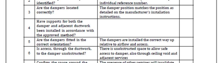
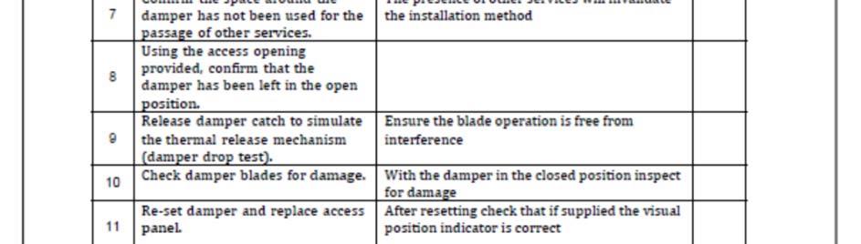
14 Burrell Way, Maintenance Report Operation / Task Result Damper reference Date of inspection Check actuator wiring for damage (where applicable) Check end-switch wiring for damage (where applicable) Check damper for cleanliness and clean where necessary Check the condition of the blades and seals, rectify and report where necessary Confirm the safety closure operation of the fire damper according to the manufacturer s instructions Confirm operation of the damper to OPEN and CLOSE by use of physical observation of the damper, rectify and report where necessary Confirm operation of OPEN and CLOSED end-switches, rectify and report (where necessary) Confirm that the damper fulfills its function as part of the control system (where necessary) Confirm that the damper is left in its normal working position 14