Table of Contents. Inside this issue: List of Tables: List of Figures: Second Edition
|
|
|
- Rhoda Houston
- 5 years ago
- Views:
Transcription
1 allanblock.com

2 Table of Contents Second Edition Inside this issue: Product Standards... 3 Installation Specifications... 5 Water Management... 7 ASTM Standards... 9 Design, Construction and Inspection Check Lists Design Details Water Management Details Geogrid Details Fencing Applications Miscellaneous Details Design Methods Allowable Construction Tolerances Geogrid Reinforcement Specifications List of Tables: Table 1: Embankment Protection Fabric Specifications...8 Table 2: Strength and Absorption Requirements (ASTM)...9 Table 3: Geogrid Manufacturers Testing Results...21 List of Figures: Figure 1: AB Unit - Approximate Dimensions... 3 Figure 2: Gravity Wall Consolidation Zone...4 Figure 3: Geogrid Wall Consolidation Zone...6 Figure 4: Surface Water Management... 7 Figure 5: Construction Water Management...7 Figure 6A: Internal Blanket...8 Figure 6B: Internal Blanket and Chimney Drain...8 Figure 7: Freeze-Thaw Testing...10 Figure 8: Global Stability...11 Figure 9: Elevation View Figure 10: Wall Site Components Figure 11: Typical Reinforcement Configurations.. 12 Figure 12: Vertical Control Figure 13: Differential Settlements...20 Figure 14: Horizontal Control Figure 15: Rotation...20 Page 1


3 Allan Block Corporation: A leader in segmental retaining wall design The following pages will provide assistance to a broad range of professional retaining wall designers. This technical specification manual will allow a wall designer to source and reference specific information for use in developing project documents. Included are: product standards, installation and water management procedures, design details, industry standards, allowable construction tolerances, project design checklist, project installation checklist, project inspection checklist, reference design methods, and geogrid reinforcement options. The goal is to provide formatted specification sheets that summarize information published by Allan Block and other relevant publications, as well as provide a comprehensive document for most applications which utilize mortarless concrete block as a component of a segmental retaining wall. Allan Block provides Site Solutions The document focuses on composite structures built by combining an Allan Block facing unit with a reinforced soil mass, and appropriate drainage details. Other methods of reinforcement will be illustrated in the Design Detail portion of this publication, but not presented in great detail. The intent of this publication is to assist the local wall design engineer, but not limit their flexibility for any given design situation. Answering the question: Can segmental retaining walls satisfy the requirements of my project? Segmental Retaining Walls (SRW s) have evolved from being used in garden and landscape applications in the 80 s and 90 s, to now having found their way into commercial projects, roadway sites, and major industrial applications. With estimates of over 120 million Allan Blocks installed worldwide, mortarless segmental retaining walls have proven their value and durability in the construction marketplace. Projects range from walls up to 50 ft (15.2 m) in height to miles of walls used in roadway, water and other applications. The flexible nature of the system has proven to eliminate the need for frost footings in northern climates, provide additional drainage in tropical areas, and allow for additional flexibility in earthquake plagued sections of the world. In short there are very few site problems that cannot find a cost effective solution using Allan Block Retaining Wall Products. Page 2
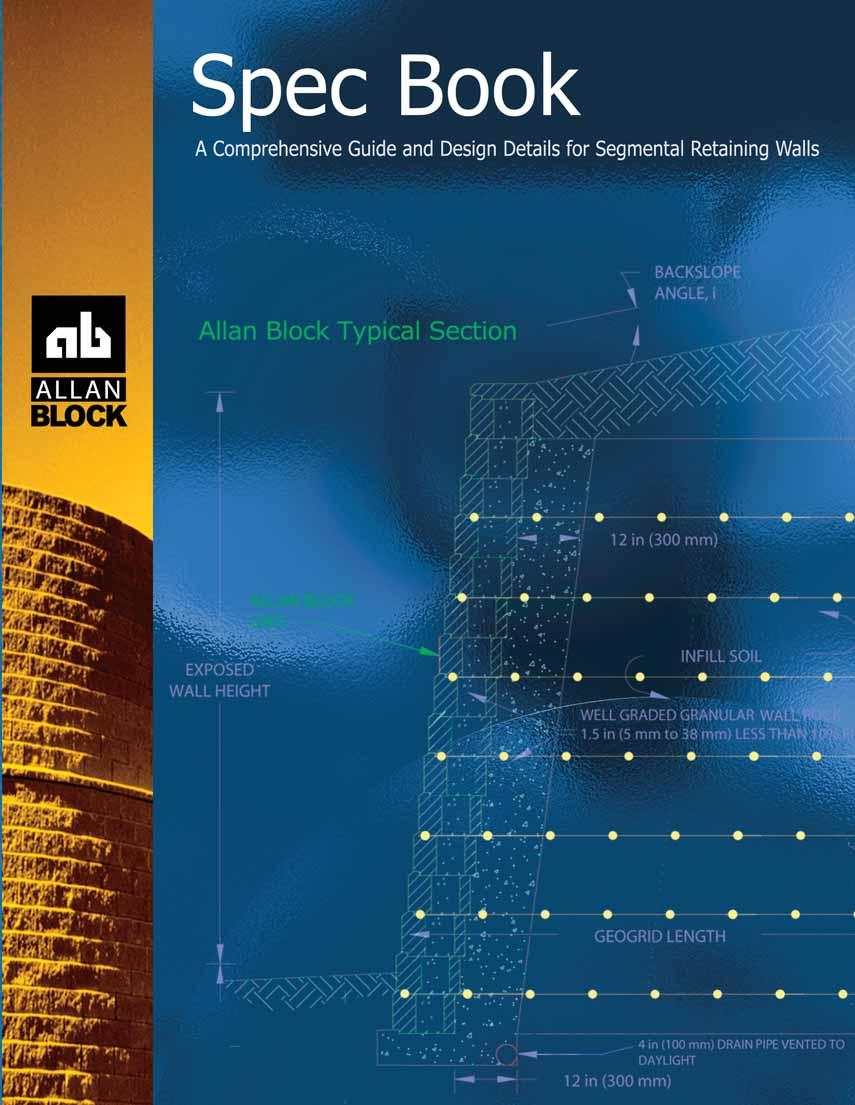
4 Allan Block Product Standards Specification Guidelines: Allan Block Modular Retaining Wall Systems The following specifications provide Allan Block Corporation's typical requirements and recommendations. At the engineer of record's discretion these specifications may be revised to accommodate site specific design requirements. SECTION 1 PART 1: GENERAL 1.1 Scope Work includes furnishing and installing modular concrete block retaining wall units to the lines and grades designated on the construction drawings and as specified herein. 1.2 Applicable Sections of Related Work Geogrid Wall Reinforcement (see Section 2, Page 5) 1.3 Reference Standards A. ASTM C Standard Specification for Segmental Retaining Wall Units. B. ASTM Evaluating the Freeze thaw Durability of Manufactured CMU s and Related concrete Units C. ASTM D698 Moisture Density Relationship for Soils, Standard Method D. ASTM D422 Gradation of Soils E. ASTM C140 Sample and Testing concrete Masonry Units 1.4 Delivery, Storage, and Handling A. Contractor shall check the materials upon delivery to assure proper material has been received. B. Contractor shall prevent excessive mud, wet cement, and like construction debris from coming in contact with the materials. C. Contractor shall protect the materials from damage. Damaged material shall not be incorporated in the project (ASTM C ). Figure 1: Standard AB Unit - Approximate Dimensions PART 2: MATERIALS 2.1 Modular Wall Units A. Wall units shall be Allan Block Retaining Wall units as produced by a licensed manufacturer. B. Wall units shall have minimum 28 day compressive strength of 3000 psi (20.7 MPa) in accordance with ASTM C The concrete units shall have adequate freezethaw protection with an average absorption rate of 7.5 lb/ft 3 (120 kg/m 3 ) for northern climates and 10 lb/ft 3 (160 kg/m 3 ) for southern climates. C. Exterior dimensions shall be uniform and consistent. Maximum dimensional deviations shall be in. (3 mm), not including textured face. D. Wall units shall provide a minimum of 110 lbs total weight per square foot of wall face area (555 kg/m 2 ). Fill contained within the units may be considered 80% effective weight. E. Exterior face shall be textured. Color as specified by owner. 2.2 Wall Rock A. Material must be well graded compactible aggregate, 0.25 in. to 1.5 in., (6 mm - 38 mm) with no more than 10% passing the #200 sieve. (ASTM D422) B. Material behind and within the blocks may be the same material. 2.3 Infill Soil A. Infill material shall be site excavated soils when approved by the on-site soils engineer unless otherwise specified in the drawings. Unsuitable soils for backfill (heavy clays or organic soils) shall not be used in the reinforced soil mass. Typically clay soils with high plasticity will not be acceptable, unless specifically addressed by the wall design engineer. B. The infill soil used must meet or exceed the designed friction angle and description noted on the design cross sections, and must be free of debris. C. Where additional fill is required, contractor shall submit sample and specifications to the wall design engineer or the on-site soils engineer for approval. PART 3: WALL CONSTRUCTION 3.1 Excavation A. Contractor shall excavate to the lines and grades shown on the construction drawings. Contractor shall use caution not to over-excavate beyond the lines shown, or to disturb the base elevations beyond those shown. B. Contractor shall verify locations of existing structures and utilities prior to excavation. Contractor shall ensure all surrounding structures are protected from the effects of wall excavation. 3.2 Foundation Soil Preparation A. Foundation soil shall be defined as any soils located beneath a wall. B. Foundation soil shall be excavated as dimensioned on the plans and compacted to a minimum of 95% of Standard Proctor (ASTM D698) prior to placement of the base material. C. Foundation soil shall be examined by the on-site soils engineer to ensure that the actual foundation soil strength meets or exceeds assumed design strength. Soil not meeting the required strength shall be removed and replaced with acceptable material. 3.3 Base A. Base material shall be placed as shown on the construction drawing. Top of base shall be located to allow bottom wall units to be buried to proper depths as per wall heights and specifications. Page 3
 to provide a level hard surface on which to place the first course of blocks.")
5 B. Base material shall be installed on undisturbed native soils or suitable replacement fills compacted at 95% Standard Proctor (ASTM D698). C. Base shall be compacted at 95% Standard Proctor (ASTM D698) to provide a level hard surface on which to place the first course of blocks. The base shall be constructed to ensure proper wall embedment and the final elevation shown on the plans. Well-graded sand can be used to smooth the top 1/2 in. (13 mm) on the base material. D. Base material shall be a 4 in. (100 mm) minimum depth for walls under 4 ft (1.2 m) and a 6 in. (150 mm) minimum depth for walls over 4 ft (1.2 m). 3.4 Unit Installation A. The first course of wall units shall be placed on the prepared base with the raised lip facing up and out and the front edges tight together. The units shall be checked for level and alignment as they are placed. B. Ensure that units are in full contact with base. Proper care shall be taken to develop straight lines and smooth curves on base course as per wall layout. C. All cavities in and around the base row shall be filled with wall rock. Backfill in front of entire base row and a 12 in. (300 mm) depth behind block with wall rock and compact to firmly lock in place. Check again for level and alignment. All excess material shall be swept from top of units. D. Install next course of wall units on top of base row. Position blocks to be offset from seams of blocks below. Perfect "running bond" is not essential, but a 3 in. (75 mm) minimum offset is recommended. Check each block for proper alignment and level. Fill all cavities in and around wall units and to a 12 in. (300 mm) depth behind block with wall rock. Spread backfill in uniform lifts not exceeding 8 in. (200 mm) in uncompacted thickness and compact to 95% of Standard Proctor (ASTM D698) behind the consolidation zone. Figure 2: Consolidation Zone - Gravity Wall E. The consolidation zone shall be defined as 3 ft (1 m) behind the wall. Compaction within the consolidation zone shall be accomplished by using a hand operated plate compactor and shall begin by running the plate compactor directly on the block and then compacting in parallel paths to the wall face until the entire consolidation zone has been compacted. A minimum of two passes of the plate compactor are required with maximum lifts of 8 in. (200 mm). Expansive or fine-grained soils may require additional compaction passes or smaller maximum lifts. Employ methods using lightweight compaction equipment that will not disrupt the stability or batter of the wall. Final compaction requirements in the consolidation zone shall be established by the engineer of record. F. Install each subsequent course in like manner. Repeat procedure to the extent of wall height. G. As with any construction work, some deviation from construction drawing alignments will occur. Variability in construction of SRWs is approximately equal to that of cast-inplace concrete retaining walls. As opposed to cast-in-place concrete walls, alignment of SRWs can be simply corrected or modified during construction. Based upon examination of numerous completed SRWs, the following recommended minimum tolerances can be achieved with good construction techniques. Refer to Page 20. Vertical Control - ±1.25 in. (32 mm) max. over 10 ft (3 m) distance. Horizontal Location Control - straight lines ±1.25 in. (32 mm) over a 10 ft (3 m) distance. Rotation - from established plan wall batter : 2.0 Bulging in. (25 mm) over a 10 ft (3.0 m) distance 3.5 Additional Construction Notes A. When one wall branches into two terraced walls, it is important to note that the soil behind the lower wall is also the foundation soil beneath the upper wall. This soil shall be compacted to a minimum of 95% of Standard Proctor (ASTM D698) prior to placement of the base material. Achieving proper compaction in the soil beneath an upper terrace prevents settlement and deformation of the upper wall. One way is to replace the soil with wall rock and compact in 8 in. (200 mm) lifts. When using onsite soils, compact in maximum lifts of 4 in. (100 mm) or as required to achieve specified compaction. B. Filter fabric use is not suggested for use with cohesive soils. Clogging of such fabric creates unacceptable hydrostatic pressures in soil reinforced structures. When filtration is deemed necessary in cohesive soils, use a three dimensional filtration system of clean sand or filtration aggregate. C. Water management is of extreme concern during and after construction. Steps must be taken to ensure that drain pipes are properly installed and vented to daylight and a grading plan has been developed that routes water away from the retaining wall location. Site water management is required both during construction of the wall and after completion of construction. Refer to Section 3, Page 7 for more water management information. Page 4

 1.3 Reference Standards See specific geogrid manufacturers reference standards.")
6 Allan Block Installation Specifications Specification Guidelines: Geogrid Reinforcement Systems The following specifications provide Allan Block Corporation's typical requirements and recommendations. At the engineer of record's discretion these specifications may be revised to accommodate site specific design requirements. SECTION 2 PART 1: GENERAL 1.1 Scope Work includes furnishings and installing geogrid reinforcement, wall block, and backfill to the lines and grades designated on the construction drawings and as specified herein. 1.2 Applicable Section of Related Work Section 1: Allan Block Modular Retaining Wall Systems. (see Section 1, page 3) 1.3 Reference Standards See specific geogrid manufacturers reference standards. Additional Standards: A. ASTM D Tensile Properties of Geotextiles by the Wide-Width Strip Method B. ASTM D Test Method for Evaluating the Unconfined Creep Behavior of Geogrids C. ASTM D6638 Grid Connection Strength (SRW-U1) D. ASTM D6916 Grid Shear Strength (SRW-U2) E. GRI Grid Long Term Allowable Design Strength (LTDS) F. GRI Grid Pullout 1.4 Delivery, Storage, and Handling A. Contractor shall check the geogrid upon delivery to assure that the proper material has been received. B. Geogrid shall be stored above -10 F (-23 C). C. Contractor shall prevent excessive mud, wet cement, or other foreign materials from coming in contact with the geogrid material. PART 2: MATERIALS 2.1 Definitions A. Geogrid products shall be of high density polyethylene or polyester yarns encapsulated in a protective coating specifically fabricated for use as a soil reinforcement material. B. Concrete retaining wall units are as detailed on the drawings and shall be Allan Block Retaining Wall Units. C. Drainage material is free draining granular material as defined in Section 1, 2.2 Wall Rock, Page 3. D. Backfill is the soil used as fill for the reinforced soil mass. E. Foundation soil is the in-situ soil. 2.2 Products Geogrid shall be the type as shown on the drawings having the property requirements as described within the manufacturers specifications. 2.3 Acceptable Manufacturers A manufacturer's product shall be approved by the wall design engineer. PART 3: WALL CONSTRUCTION 3.1 Foundation Soil Preparation A. Foundation soil shall be excavated to the lines and grades as shown on the construction drawings, or as directed by the on-site soils engineer. B. Foundation soil shall be examined by the on-site soils engineer to assure that the actual foundation soil strength meets or exceeds assumed design strength. C. Over-excavated areas shall be filled with compacted backfill material approved by on-site soils engineer. D. Contractor shall verify locations of existing structures and utilities prior to excavation. Contractor shall ensure all surrounding structures are protected from the effects of wall excavation. 3.2 Wall Construction Wall construction shall be as specified under Section 1, Part 3, Wall Construction, Page Geogrid Installation A. Install Allan Block wall to designated height of first geogrid layer. Backfill and compact last 8 in. (200 mm) lift behind wall to depth equal to designed grid length before grid is installed. B. Cut geogrid to designed embedment length and place on top of Allan Block to back edge of lip. Extend away from wall approximately 3% above horizontal on compacted backfill. C. Lay geogrid at the proper elevation and orientations shown on the construction drawings or as directed by the wall design engineer. Page 5


7 D. Correct orientation of the geogrid shall be verified by the contractor and on-site soils engineer. Strength direction is typically perpendicular to wall face. E. Follow manufacturers guidelines for overlap requirements. In curves and corners, layout shall be as specified in Design Detail 9-12: Using Grid With Corners and Curves, Page 15. F. Place next course of Allan Block on top of grid and fill block cores with wall rock to lock in place. Remove slack and folds in grid and stake to hold in place. G. Adjacent sheets of geogrid shall be butted against each other at the wall face to achieve 100 percent coverage. H. Geogrid lengths shall be continuous. Splicing parallel to the wall face is not allowed. 3.4 Fill Placement A. Infill material shall be placed in lifts and compacted as specified under Section 1, Part 3.4, Page 4, Unit Installation. B. Backfill shall be placed, spread and compacted in such a manner that minimizes the development of slack or movement of the geogrid. D. When fill is placed and compaction cannot be defined in terms of Standard Proctor Density, then compaction shall be performed using ordinary compaction process and compacted so that no deformation is observed from the compaction equipment or to the satisfaction of the engineer of record or the site soils engineer. E. Tracked construction equipment shall not be operated directly on the geogrid. A minimum backfill thickness of 6 in. (150 mm) is required prior to operation of tracked vehicles over the geogrid. Turning of tracked vehicles should be kept to a minimum to prevent tracks from displacing the fill and damaging the geogrid. F. Rubber-tired equipment may pass over the geogrid reinforcement at slow speeds, less than 10 mph (16 Km/h). Sudden braking and sharp turning shall be avoided. G. The infill shall be compacted to achieve 95% Standard Proctor (ASTM D698). Compaction tests shall be taken at 3 ft (1 m) behind the block and at the back of the reinforced zone and frequency shall be as determined by the on-site soils engineer or as specified on the plan. Soil tests of the backfill material shall be submitted to the on-site soils engineer for review and approval prior to the placement of any backfill. The contractor is responsible for achieving the specified compaction requirements. The on-site soils engineer may direct the contractor to remove, correct or amend any soil found not in compliance with written specifications. C. Only hand-operated compaction equipment shall be allowed within 3 ft (1 m) behind the wall. This area shall be defined as the consolidation zone. Compaction in this zone shall begin by running the plate compactor directly on the block and then compacting in parallel paths to the wall face until the entire consolidation zone has been compacted. A minimum of two passes of the plate compactor are required with maximum lifts of 8 in. (200 mm). Section 1, Part 3.4 E, Page 4. Figure 3: Consolidation Zone - Reinforced Zone 3.5 Special Considerations A. Geogrid can be interrupted by periodic penetration of a column, pier or footing structure. B. Allan Block walls will accept vertical and horizontal reinforcing with rebar and grout. C. If site conditions will not allow geogrid embedment length, consider the following alternatives: Masonry Reinforced Walls Soil Nailing Earth Anchors Double Wall No-Fines Concrete See Design Details Page 17 and 18. D. Allan Block may be used in a wide variety of water applications as indicated in Section 3, Part 1.8, Page 8. Page 6

8 Allan Block Water Management Specification Guidelines: Water Management The following specifications provide Allan Block Corporation's typical requirements and recommendations. At the engineer of record's discretion these specifications may be revised to accommodate site specific design requirements. Section 3 PART 1: GENERAL DRAINAGE 1.1 Surface Drainage Rainfall or other water sources such as irrigation activities collected by the ground surface atop the retaining wall can be defined as surface water. Retaining wall design shall take into consideration the management of this water. A. At the end of each day s construction and at final completion, grade the backfill to avoid water accumulation behind the wall or in the reinforced zone. B. Surface water must not be allowed to pond or be trapped in the area above the wall or at the toe of the wall. C. Existing slopes adjacent to retaining wall or slopes created during the grading process shall include drainage details so that surface water will not be allowed to drain over the top of the slope face and/or wall. This may require a combination of berms and surface drainage ditches. D. Irrigation activities at the site shall be done in a controlled and reasonable manner. E. Surface water that cannot be diverted from the wall must be collected with surface drainage swales and drained laterally in order to disperse the water around the wall structure. Construction of a typical swale system shall be in accordance with Design Detail 5: Swales, Page Grading The shaping and recontouring of land in order to prepare it for site development is grading. Site grading shall be designed to route water around the walls. Figure 4: Surface Water Management A. Establish final grade with a positive gradient away from the wall structure. Concentrations of surface water runoff shall be managed by providing necessary structures, such as paved ditches, drainage swales, catch basins, etc. B. Grading designs must divert sources of concentrated surface flow, such as parking lots, away from the wall. 1.3 Drainage System The internal drainage systems of the retaining wall can be described as the means of eliminating the buildup of incidental water which infiltrates the soils behind the wall. Drainage system design will be a function of the water conditions on the site. Adequate drainage facilities will be required to completely drain the retaining wall structure. Page 7 A. All walls will be constructed with a minimum of 12 in. (300 mm) of wall rock directly behind the wall facing. The material shall meet or exceed the specification for wall rock outlined in Section 1, 2.2 Wall Rock, Page 3. B. The drainage collection pipe, drain pipe, shall be a 4 in. (100 mm) perforated or slotted PVC, or corrugated HDPE pipe as approved by engineer of record. C. All walls will be constructed with a 4 in. (100 mm) diameter drain pipe placed at the lowest possible elevation within the 12 in. (300 mm) of wall rock. This drain pipe is referred to as a toe drain, Section 3, 1.4 Toe Drain, Page 7. D. Geogrid Reinforced Walls shall be constructed with an additional 4 in. (100 mm) drain pipe at the back bottom of the reinforced soil mass. This drain pipe is referred to as a heel drain, Section 3, 1.5 Heel Drain, Page 8. Figure 5: Construction Water Management 1.4 Toe Drain A toe drain pipe should be located at the back of the wall rock behind the wall as close to the bottom of the wall as allowed while still maintaining a positive gradient for drainage to daylight, or a storm water management system. Toe drains are installed for incidental water management not as a primary drainage system. A. For site configurations with bottoms of the base on a level plane it is recommended that a minimum one percent gradient be maintained on the placement of the pipe with outlets on 50 ft (15 m) centers, or 100 ft (30 m) centers if pipe is crowned between the outlets. This would provide for a maximum height above the bottom of the base in a flat configuration of no more than 6 in. (150 mm). B. For rigid drain pipes with drain holes the pipes should be positioned with the holes located down. Allan Block does not require that toe drain pipes be wrapped when installed into base rock complying with the specified wall rock material. C. Pipes shall be routed to storm drains where appropriate or through or under the wall at low points when the job site grading and site layout allows for routing. Appropriate details shall be included to prevent pipes from being crushed, plugged, or infested with rodents. D. On sites where the natural drop in grade exceeds the one percent minimum, drain pipes outlets shall be on 100 foot (30 m) centers maximum. This will provide outlets in the event that excessive water flow exceeds the capacity of pipe over long stretches. E. When the drain pipe must be raised to accommodate outlets through the wall face, refer to the Design Detail 4: Alternate Drain, Page 14.
9 1.5 Heel Drain The purpose of the heel drain is to pick up any water that migrates from behind the retaining wall structure at the cut and route the water away from the reinforced mass during the construction process and for incidental water for the life of the structure. A. The piping used at the back of the reinforced mass shall have a one percent minimum gradient over the length, but it is not critical for it to be positioned at the very bottom of the cut. Additionally the entire length of the pipe may be vented at one point and should not be tied into the toe drain. B. The pipe may be a rigid pipe with holes at the bottom with an integral sock encasing the pipe or a corrugated perforated flexible pipe with a sock to filter out fines when required based on soil conditions. For infill soils with a high percentage of sand and/or gravel the heel drain pipe does not need to be surrounded by drainage rock. When working with soils containing more than fifty percent clay, one cubic foot of drainage rock is required for each foot of pipe. 1.6 Ground Water Ground water can be defined as water that occurs within the soil. It may be present because of surface infiltration or water table fluctuation. Ground water movement must not be allowed to come in contact with the retaining wall. A. If water is encountered in the area of the wall during excavation or construction, a drainage system (chimney, composite or blanket) must be installed as directed by the wall design engineer. Figure 6A: Figure 6B: Internal Blanket Internal Blanket and Chimney Drain B. Standard retaining wall designs do not include hydrostatic forces associated with the presence of ground water. If adequate drainage is not provided the retaining wall design must consider the presence of the water. C. When non-free draining soils are used in the retained zone, the incorporation of a chimney and blanket drain should be added to minimize the water penetration into the reinforced mass. Refer to Design Detail 6: Chimney and Blanket Drain, Page Concentrated Water Sources All collection devices such as roof downspouts, storm sewers, and curb gutters are concentrated water sources. They must be designed to accommodate maximum flow rates and to vent outside of the wall area. A. All roof downspouts of nearby structures shall be sized with adequate capacity to carry storm water from the roof away from the wall area. They shall be connected to a drainage system in closed pipe and routed around the retaining wall area. B. Site layout must take into account locations of retaining wall structures and all site drainage paths. Drainage paths should always be away from retaining wall structures. C. Storm sewers and catch basins shall be located away from retaining wall structures and designed so as not to introduce any incidental water into the reinforced soil mass. D. A path to route storm sewer overflow must be incorporated into the site layout to direct water away from the retaining wall structure. 1.8 Water Application Retaining walls constructed in conditions that allow standing or moving water to come in contact with the wall face are considered water applications. These walls require specific design and construction steps to ensure performance. Refer to Design Detail 7 and 8: Water Applications, Page 14. Table 1: Embankment Protection Fabric Specifications Mechanical Determination Property Method Tensile Strength = 375 lbs (170 kg) ASTM D-4632 Puncture Strength = 145 lbs (66 kg) ASTM D-3787 Equivalent Opening Size (EOS) = 70 CW (U.S. Sieve #) Mullen Burst = 480 psi (3.3 Mpa) ASTM D-3786 Trapezoidal Tear = 105 lbs (48 kg) ASTM D-4533 Percent Open Area = 4% CW Permeability = 0.01 cm/sec ASTM D-4491 A. Embankment protection fabric is used to stabilize rip rap and foundation soils in water applications and to separate infill materials from the retained soils. This fabric should permit the passage of fines to preclude clogging of the material. Embankment protection fabric shall be a high strength polypropylene monofilament material designed to meet or exceed typical Corps of Engineers plastic filter fabric specifications (CW-02215); stabilized against ultraviolet (UV) degradation and typically exceeding the values in Table 1. B. Infill material shall be free draining to meet the site requirements based on wave action and rapid draw down conditions. C. Rip-rap or alternative products such as Trilock may be required as a toe protector to eliminate scour at the base of the wall. Page 8
10 ASTM C Standard Specifications for Segmental Retaining Wall Units Specification Guidelines: Product Specifications for Segmental Retaining Wall Units Section 4 The following summarizes the contents of ASTM C and key components relevant when specifying modular concrete block for use in structural retaining wall designs. A copy of the full standard is available upon request. This summary attempts to provide the information which is most commonly used, but Allan Block does not claim that all information contained in the standard is represented. 1. Scope 1.1 This specification covers dry-cast segmental retaining wall units of concrete, machine made from hydraulic cement, water, and suitable mineral aggregates with or without the inclusion of other materials. The units are intended for use in the construction of mortarless segmental retaining walls. 5. Physical Requirements 5.1 At the time of delivery to the work site, the units shall conform to the physical requirements of Table 2 when tested in accordance with Freeze-Thaw Durability In areas where repeated freezing and thawing under saturated conditions occur, freezethaw durability shall be demonstrated by test or by proven field performance that the segmental retaining wall units have adequate durability for the intended use. When testing is required by the specifier to demonstrate freeze-thaw durability, the units shall be tested in accordance with Specimens shall comply with either of the following: (1) the weight loss of each of five test specimens at the conclusion of 100 cycles shall not exceed 1 % of its initial weight; or (2) the weight loss of each of four of the five test specimens at the conclusion of 150 cycles shall not exceed 1.5 % of its initial weight. TABLE 2: Strength and Absorption Requirements (ASTM) Minimum Required Net Average Compressive Strength, psi (MPa) Average of 3 units Individual Unit 3000 (20.7) 2500 (17.2) Maximum Water Absorption Requirements, lb/ft 3 (kg/m 3 ) Weight Classification Oven-Dry Density of Concrete lb/ft 3 (kg/m 3 ) Light Weight Medium Weight Normal Weight Less than 105 (1682) 105 (1682) to less than 125 (2002) 125 (2002) or more 18 (288) 15 (240) 13 (208) 6. Permissible Variations in Dimensions 6.1 Overall dimensions for width, height, and length shall differ by not more than ± 1/8 in. (3.2 mm) from specified standard dimensions Dimensional tolerance requirements for width shall be waived for architectural surfaces. 7. Finish and Appearance 7.1 All units shall be sound and free of cracks or other defects that interfere with the proper placement of the unit or significantly impair the strength or permanence of the construction. Minor cracks incidental to the usual method of manufacture or minor chipping resulting from customary methods of handling in shipment and delivery, are not grounds for rejection. 7.2 Where units are to be used in exposed wall construction, the face or faces that are to be exposed shall not show chips or cracks, not otherwise permitted, or other imperfections when viewed from a distance of not less than 20 ft (6.1 m) under diffused lighting Five percent of a shipment containing chips not larger than 1 in. (25.4 mm) in any dimension, or cracks not wider than 0.02 in. (0.5 mm) and not longer than 25 % of the nominal height of the unit is permitted. 7.3 The color and texture of units shall be specified by the purchaser. The finished surface that will be exposed in place shall conform to an approved sample consisting of not less than four units, representing the range of texture and color permitted. 8. Sampling and Testing 8.1 The purchaser or authorized representative shall be accorded proper facilities to inspect and sample units at the place of manufacture from the lots ready for delivery. 8.2 Sample and test units for compressive strength, absorption, and dimensional tolerances in accordance with Test Methods C When required, sample and test five specimens for freeze-thaw durability in water in accordance with Test Method C Freeze-thaw durability shall be based on tests of units made with the same materials, concrete mix design, manufacturing process, and curing method, conducted not more than 24 months prior to delivery. 9. Compliance 9.1 If a sample fails to conform to the specified requirements, the manufacturer shall be permitted to remove units from the shipment. A new sample shall be selected by the purchaser from remaining units from the shipment with a similar configuration and dimension and tested at the expense of the manufacturer. If the second sample meets the specified requirements, the remaining portion of the shipment represented by the sample meets the specified requirements. If the second sample fails to meet the specified requirements, the remaining portion of the shipment represented by the sample fails to meet the specified requirements. Page 9
11 ASTM C Standard Test Method for Evaluating the Freeze-Thaw Durability of Manufactured Concrete Masonry Units and Related Concrete Units The following summarizes the contents of ASTM C 1262 and key components of the test methods used to determine relative freeze thaw durability. This does not provide a comparison to field performance but a systematic approach to testing. A copy of the full standard is available upon request. This summary attempts to provide the information which is most commonly used, but Allan Block does not claim that all information contained in the standard is represented. 1. Scope 1.1 This test method covers the resistance to freezing and thawing manufactured concrete masonry and related concrete units. Units are tested either in water or in a saline solution depending on the intended use of the units in actual service. Note 1 Concrete masonry and related concrete units include units such as hollow and solid concrete masonry units, concrete brick, segmental retaining wall units, concrete pavers, and concrete roof pavers. 4. Significance and Use 4.1 The procedure described in this test method is intended to determine the effects of freezing and thawing on concrete units in the presence of water or saline solution. 4.2 The procedure is not intended to provide a quantitative measure of the length of service that may be expected from a specific type of concrete unit. 6. Sampling 6.1 Selection of Test Specimens Select whole units representative of the lot from which they are selected. The units shall be free from visible cracks or structural defects. 6.2 Number of Specimens Select five units for freezing and thawing tests. If compression and absorption tests are to be performed on the same set of units in accordance with Test Methods C 140, select additional units as required. Specimens (coupons) used for Test Methods C 140 tests shall not be used as specimens for freezing and thawing tests. 7. Preparation of Test Specimens 7.1 Freezing and Thawing Test Specimens Test specimens shall consist of solid coupons saw-cut from full sized units. Do not saw-cut test specimens from units that have been previously oven-dried. Do not subject test specimens to ovendrying prior to completion of freezing and thawing testing One coupon shall be cut from each of the five sampled units. Using a water-cooled saw, cut the coupon from the exposed surface of the unit as the unit is used in service unless the exposed surface is a split, fluted (ribbed), or other nonplanar surface. In the case of a unit with an exposed nonplanar surface, cut the coupon from another flat molded surface. Immediately following saw-cutting, remove loose particles and residue from the coupon by rinsing in tap water and brushing with a soft bristle brush. Do not fully immerse coupons in water. 8. Procedure 8.1 Specimen Conditioning: After preparation of the freezing and thawing test specimens in accordance with Section 7, place the specimen in the container face down on the specimen supports such that the non- saw-cut surface of the specimen is in contact with the specimen supports. Add a sufficient amount of water at a temperature of 60 to 80 F (16 to 27 C) to the container to achieve a water depth of 1/2 ± 1/16 in. (13 ± 2 mm). Do not pour water directly onto the specimen. For test specimens being evaluated for freezing and thawing durability in saline solutions, use a 3 ± 0.1 % (by weight) sodium chloride saline solution in lieu of water in the container. Seal the container and store on a level surface in laboratory air as defined in Cyclical Testing: One freezing and thawing cycle is defined as a completed freezing cycle followed by a completed thawing cycle At 25 ± 5 cycle intervals, remove containers from the test chamber. Open containers to visually inspect the condition of the specimens and to adjust the water level to comply with Collection of Residue: Weigh to the nearest 0.2 g ( lb) and record as Wf a filter paper of high wet strength and smooth surface that has come to equilibrium temperature with the lab environment. Remove a single specimen from its container. Immediately rinse the specimen with water (if the specimen is tested in saline solution, use saline solution to rinse the specimen) using a squeeze bottle, being careful to collect in the specimen container the rinse water and all loose particles from the specimen. Consider any pieces that separated from the specimen as part of the residue. Pour the water (or saline solution) from the specimen container through the filter paper to collect the residue (spall) from the test specimen. Replace the specimen in the container. Using fingertips and a squeeze bottle, remove loose particles from all surfaces of the specimen, again being careful to collect all rinse water and loose particles in the specimen container. The top surface of the specimen shall not be immersed in water at anytime and the collected rinse water shall not exceed a depth of 1.2 in. (13 mm) in the container. Remove the specimen from the container, pour the rinse water through the filter paper, and rinse the specimen container until all residue (spall) in the specimen container is collected on the filter paper. Rinse the residue from specimens tested in saline solution three times with water to remove any soluble salt. 9. Calculation and Report 9.1 Determine and report the cumulative weight loss of each residue collection interval expressed in terms of g (lb) and as a percent of the calculated initial weight of the specimen, W initial, determined in accordance with Where the coupon thickness is less than 1.25 in. (32 mm), the percentage and cumulative weight loss shall be multiplied by a value equal to the actual thickness in inches (mm) divided by 1.25 in. (32 mm). Report these values for each specimen as well as the average of the specimens tested. Figure 7: Freeze-Thaw Testing Page 10
12 Wall Design Checklist To ensure that the basics are covered in your wall design we have prepared the following wall design checklist. It may also be used by someone checking your work to provide an outline for a consistent review process. Review Wall Design Plans For Special Conditions: Site Drainage Layout Global Stability Government Regulations High Water Table Seismic Design Requirements Review Wall Design Plans For: Overall Length of Wall Station Points Plan Layout Elevations Grades or Slopes Above or Below Walls Soil Conditions Retained Soil Friction Angle Infill Soil Friction Angle Foundation Soil Friction Angle Cohesion for Foundation Soil Soil Settlement Potential Water Management Above Grade Below Grade Excess Irrigation Locations of Catch Basins and Utilities Compliance to Specifications Surcharges (live, dead, and location) Temporary Construction Loads Snow or Storage Loads Special Provisions Design Review: Grid Length Grid Spacing Grid Placed on Consistent Courses Design Factors of Safety Sliding Overturning Bearing Grid Overstress Pullout from Soil Pullout from Block Global Seismic Water Management Details Surface Water Sources Sub Surface Water Sources Details for Low Permeability Soils Location and Venting of Toe and Heel Drains Overall Quantity Estimates Block Grid Wall Rock Construction Details General Notes and Specifications Page 11 Figure 8: Figure 9: Figure 10: Global Stability Elevation View Wall Site Components
13 Construction and Inspection Checklist We have prepared the following Construction and Inspection Checklist to provide a list of items covering the basics for your retaining wall project. It may also be used during the bidding process to ensure that all special provisions are complied with. Always check your local building codes, document any changes to the plan in writing and notify the wall design engineer with any concerns on water management. Review Wall Design Plans For: Figure 11: Typical Reinforcement Configuration A. Compliance of Site to Latest Site Plan Does the site plan and wall layout coincide with current Site Conditions? Have all slopes above and below the walls been taken into account on the plans? Do the section drawings match the topography of the job-site? Have site utilities been accounted for? Are there any recommendations for changes to the site plans to accommodate the wall? B. Review of Reported Soil Conditions with On-Site Soils Engineer Are on-site soils consistent with soil parameters used in wall design? Does the site show indications of multiple types of soil, and has this been accounted for? Is there evidence of landfill areas on site? C. Review of Above Grade Water Management with Project Civil Engineer Has surface runoff been accounted for in the site design? Will this site be irrigated? If storm drains become inoperable where will the water migrate to? During renovation of land will temporary drainage be an issue? Review Construction Details And Procedures: A. Mark station points for top and bottom of wall elevations and changes in wall direction. B. Identify changes in grid lengths, location of grids, and types of grid to be used. C. Determine and locate proper base size for each section of wall. D. Verify that the correct type and color of block has been ordered and delivered to the job. E. Verify that the foundation soil and retained soil conform to design requirements. F. Verify that infill soil meets design standards. G. Verify that compaction testing will be performed, who is responsible, at what intervals of locations along the wall, and what coordination will be required. H. Determine what method will be used to verify construction materials, methods, and sequence of construction. (ie: written documentation of as built, full time inspector on site, photographic documentation.) D. Review of Below Grade Water Management with Wall Design Engineer and General Contractor How and where will drain pipes be installed? Is it possible to vent drain pipes to daylight? Is venting to a storm drainage system an option? Will outlets be located and protected from blockage or damage? E. Surcharges Have all surcharges been accounted for? During construction are there any temporary surcharges that should be accounted for? Page 12

14 Design Details All drawings are for information only and not for construction. See the approved plans for exact details or contact the local engineer of record for written guidance. Detail 1: Typical Reinforced Wall Application Detail 2: Typical Gravity Wall Application Detail 3: Allan Block Plantable Wall Page 13


15 All drawings are for information only and not for construction. See the approved plans for exact details or contact the local engineer of record for written guidance. Detail 4: Alternate Drain Detail 5: Swales Detail 6: Chimney and Blanket Drain Detail 7: Taller Height Reinforced Water Applications Detail 8: Low Height Reinforced Water Applications Page 14


16 Design Details All drawings are for information only and not for construction. See the approved plans for exact details or contact the local engineer of record for written guidance. Detail 9: Inside Corner Geogrid Overlap Detail 10: Outside Corner Geogrid Overlap Detail 11: Inside Curve Geogrid Overlap Detail 12: Outside Curve Geogrid Overlap Detail 13: Step Up at Base Course Detail 14: Grouted Connection Page 15


17 All drawings are for information only and not for construction. See the approved plans for exact details or contact the local engineer of record for written guidance. Detail 15: Non-Wind Bearing Fence or Railing, Option 1 Detail 16: Non-Wind Bearing Fence or Railing, Option 2 Detail 17: Alternate Fence Footing with SLEEVE-IT Footing System Detail 18: Wind Bearing Fence or Railing, Option 1 Detail 19: Wind Bearing Fence or Railing, Option 2 Detail 20: Masonry Parapet Page 16


18 Design Details All drawings are for information only and not for construction. See the approved plans for exact details or contact the local engineer of record for written guidance. Detail 21: Double Wall Parapet Detail 22: Non-Impact Parking Railing Detail 23: Impact Roadway or Parking Guard Rail Detail 24: No-Fines Concrete Detail 25: Concrete Collar Storm Water Pipe Outlet, Section and Elevation View Page 17


19 All drawings are for information only and not for construction. See the approved plans for exact details or contact the local engineer of record for written guidance. Detail 26: Terraced Section Detail 27: Allan Block Double Wall Typical Section Detail 28: Allan Block Masonry Reinforced Typical Section Detail 29: Allan Block Veneer Typical Section Detail 30: Allan Block Facing to Soil Nail Reinforced Shotcrete Wall Detail 31: Allan Block Facing to Earth Anchor Tiebacks Page 18
20 Design Methods The following information is intended to provide insight into the basic concepts behind an Allan Block retaining wall design. A complete review of the methodology and the equations may be found by reviewing the Allan Block Engineering Manual. Allan Block walls are most often designed and constructed as either gravity walls or coherent gravity masses, but can be used in many different types of retaining wall applications; Gravity Walls are structures that resist the pressures from the retained soil with the weight of the facing. Under optimum conditions Allan Block gravity walls may be constructed up to 5.5 ft (1.7 m). Coherent Gravity Masses act as large composite structures. These structures are a flexible unified mass that resist the forces from the retained soil in the same manner as a simple gravity wall. These composite structures are composed of geogrid reinforced soil masses with Allan Block Retaining Walls used as a durable, aesthetically pleasing, facing material. Other reinforcement options include Tie Back Walls or Masonry Reinforcement. Tie Backs utilize Allan Block as a hard facing with some type of anchor used to tie back the facing. Designs of this type develop loads at the face and end of the anchor and do not perform as a coherent gravity mass. Masonry reinforcement applications use grout and rebar through the cores of the Allan Block to create a high strength cantilever wall. Allan Block Corporation has developed several tools to help the design engineer through the design process. Available tools include: Allan Block Engineering Manual providing detailed calculations and commentary for the methods and processes used in the design procedure. AB Walls 2000 a Windows based software design program that is a tool for the designer and allows configuration a wall structure that is appropriate for the site and application. This software also allows the designer to calculate cross sections, elevation views, plan views and material estimates that are all coordinated and export them to AutoCAD format. Hand Calculations a MathCAD based file that contains all of the detailed calculations for the engineer to review as well as providing the engineer the ability to revise the equations to fit the particular need of the job in process while providing a method to cross check the output of AB Walls The basic elements of the design process require an understanding of the properties of the soils to be used behind and below the retaining wall, terrain changes above or below the retaining structure, surcharges located above the wall, and seismic loading if appropriate. The design calculation process has two categories of stability to be checked; external stability and internal stability. External stability analysis applies to the outside of the retaining wall or reinforced mass. The forces exerted on the structure are calculated by using an equation developed by Coulomb in 1776 called active earth pressure. The term active refers to the ability of the wall structure to rotate and bend in small increments Page 19 without adversely affecting the stability. This equation takes into account the strength of the soil, slope of the backfill, the batter of the retaining wall, and the effects of the friction between the retained soil and the retaining wall structure. When addressing external stability the engineer will design for adequate factors of safety with respect to overturning (eccentricity), sliding, bearing capacity, and global stability. F = (0.5)( )(K a )(H) 2 K a = csc( ) sin ( - ) sin( w ) sin( w ) sin( i) sin( i) = Soil Unit Weight Internal stability applies to forces and reactions within the blocks and geogrid reinforcement. Here a designer will check for adequacy in block to reinforcement connection strength, reinforcement pullout from the soil, and reinforcement overstress. See geogrid reinforcement specifications section for further explanation of how geogrid works. Refer to Page 21. Retaining wall designs rely heavily on the site soil properties. At the beginning of the design process a value is assigned to the soil that numerically describes how much resistance to movement this soil possesses. This resistance to movement is called the internal friction angle (, PHI). As the internal friction of the soil increases it exerts less force on the retaining wall. Soils that contain high percentages of sands and gravel have higher friction angles, drain away excess water more readily, and are easier to use during the construction process. For these reasons soils with sand and gravel are preferred materials to use when constructing a reinforced soil structure. Soils exhibit another property that resists movement called cohesion, which is typically found in clay soils. Cohesion may be classified as temporary strength because it depends greatly on moisture content of the soil, because of this it is not utilized in most elements of the design process. Water pressure is not considered in a typical design. Because water adversely affects the strength and weight properties of soil within the composite structure, primary consideration should be given to manage water away from the retaining wall structure. These structures have been developed to drain away only incidental water which may infiltrate the mass during or after construction. The wall rock and drain pipe are included to keep the surrounding soil at its optimum moisture content. A designer must also consider aspects of the retaining wall that are not solved in calculations. They must address all the elements surrounding the structure and set construction standards. Compaction requirements, geogrid spacing, and geogrid length are a few of these items to consider. (See Allan Block Tech Sheet #598 Designing Balance Into Your Retaining Wall Project for further information). Allan Block products can be used for almost any application. Incorporating these design concepts will help any engineer create a safe, aesthetically pleasing, and cost effective retaining wall.
21 Allowable Construction Tolerances Construction Tolerances To ensure that acceptable work standards are understood during retaining wall installation, construction tolerances need to be established. These construction tolerances should consider that the retaining wall is designed to be a flexible structure that tolerates horizontal and vertical variation. However, too much variation can affect the structural stability of the wall. To maintain horizontal and vertical control, adjustments may be required during modular block installation. Even with tight quality control procedures by block manufactures, modular block units may vary in height. Shimming a maximum of in. (3 mm) per block is acceptable construction practice. It is recommended that shimming material be asphaltic or non-degradable products. Acceptable construction tolerances are illustrated in Figures 12 thru 15. Figure 12: Vertical Control Differential Settlement Foundation settlements must be estimated with great care for buildings, bridges, towers, power plants, and similar high-cost structures. For structures such as fills, earth dams, levees, and retaining walls a greater margin of error in settlements can usually be tolerated. The construction method of placing the dry-stacked mortarless Allan Block on an aggregate leveling pad creates a flexible but stable retaining wall. Settlement errors that are acceptable while maintaining structural integrity include large total wall settlement and moderate differential settlement as depicted in Figure 13. Settlement occurs when the weight of the retaining wall structure exceeds the bearing capacity of the soil. Cohesionless soils consisting of sands and gravels often exhibit very little settlement with most of the settlement occurring during or shortly after wall construction. Cohesive soils with high moisture content have the potential for large time-depended settlement because the weight of the wall can actually compress the foundation soil. The settlement can be estimated using conventional one-dimensional consolidation calculations. When anticipated settlement is greater than the construction tolerances, special design and construction steps need to be taken. Post Construction Finish and Appearance Depending on wall heights, surcharges, soil conditions and foundation materials, some stress cracks may occur in the wall during and after construction. Since Allan Block walls are flexible structures, some cracking of block is likely, as are spaces between blocks as the wall moves. These openings should not exceed 0.25 in. (6 mm) and do not affect the structural integrity of the wall. Figure 13: Differential Settlement Figure 14: Horizontal Control Figure 15: Rotation Page 20

22 Geogrid Reinforcement Specifications Every building we live and work in calls on various materials to blend strength and functionality to create a finished product that provides us with a safe living space incorporating the amenities that we desire. The development of geosynthetics to reinforce soil masses has paved the way to a new industry utilizing concrete block as a facing for these composite retaining wall structures. Allan Block walls that cannot rely on the weight of the block alone to retain soil typically use geogrid reinforcement to develop a larger mass. Geogrids are flexible synthetic meshes produced from high strength polyester fibers encapsulated in protective coating. They work perfectly with on-site soils and modular retaining wall products because of their strength, durability, workability and overall economy. Soil reinforcement is a concept that dates back to the times of Babylonia and the construction of the Great Wall of China when non-degradable tree branches were placed in between layers of compacted soil. Whether it is tree branches or coated synthetic fibers, these products are used to create a reinforced coherent mass behind the retaining wall by stabilizing the mass and increasing the internal strength of the soil. multi-point connection. With over 120 million square feet of Allan Block products in the ground we have not had one case of the retaining wall block pulling away from the soil mass. Most geogrid mats are stronger in one direction of orientation. The primary strength direction is commonly referred to as the machine or roll direction. Geogrid mats are typically rolled perpendicular to the face of the wall to utilize the long term allowable design strength (LTDS) of the geogrid. The transverse strands are in place to maintain consistent spacing of the load carrying strands, and can be half the strength of the primary strands. The LTDS value of geogrid accounts for varying soil strengths, installation damage, chemical degradation, and creep. The mechanical properties of various brands of geogrid are given in Table 3. LTDS values are given by the geogrid manufacturers testing results. Allan Block connection strengths are per ASTM D6638 (also explained in NCMA SRWU-1). Geogrid interacts with soil by using friction as well as passive resistance. This interaction happens both in the infill soil and the "rock-lock" connection of the block to the geogrid. The block to geogrid connection is created when the gravel material in the hollow cores of the Allan Block units are compacted, interlocking the gravel with the apertures of the geogrid. The gravel helps creates superior resistance to pullout because it is a uniform, Table 3: Geogrid Engineering Properties GEOGRID TYPE Fortrac 20/9-20 Fortrac 35/20-20 Fortrac 55/30-20 Fortrac 80/30-20 Miragrid 2XT Miragrid 3XT Mirafi 5XT Mirafi 7XT Mirafi 8XT Mirafi 10XT Strata 150 Strata 200 Strata 350 Strata 500 Raugrid 2/3-30 Raugrid 3/3-20 Raugrid 4/2-15 Raugrid 6/3-15 LONG TERM ALLOWABLE DESIGN STRENGTH, LTDS lb/ft (kn/m) SAND- SILT-CLAY 762 (11.10) 1322 (19.30) 1936 (28.30) 2815 (41.10) 949 (13.80) 1558 (22.70) 2234 (32.60) 2961 (43.20) 3089 (45.07) 4116 (60.05) 1008 (14.70) 1613 (23.60) 2259 (33.00) 2796 (40.80) 737 (10.75) 1172 (17.10) 1517 (22.13) 2077 (30.30) SAND- GRAVEL 728 (10.60) 1300 (19.00) 1882 (27.50) 2815 (41.10) 839 (12.20) 1423 (20.80) 2040 (29.80) 2704 (39.40) 3007 (43.87) 4006 (58.45) 962 (14.10) 1540 (22.50) 2156 (31.50) 2669 (39.00) 712 (10.39) 1131 (16.50) 1464 (21.36) 2004 (29.24) GRAVEL 572 (8.40) 1243 (18.10) 1783 (26.00) 2615 (38.20) 727 (10.60) 1309 (19.10) 1875(27.40) 2487 (36.30) 2719 (39.87) 3622 (52.84) 882 (12.90) 1412 (20.60) 1976 (28.90) 2447 (35.70) 693 (10.11) 1102 (16.08) 1427 (20.82) 1953 (28.49) REDUCTION FACTOR CREEP, RFcr PEAK CONNECTION STRENGTH EQUATIONS, Tu SEGMENT #1 lb/ft SEGMENT #1 kn/m (SEGMENT 2) (SEGMENT 2) T u = 726 lb/ft + Ntan(3 ) T u = 1313 lb/ft + Ntan(8 ) T u1 = 1373 lb/ft + Ntan(41 ) (T u2 = 2600 lb/ft) T u1 = 680 lb/ft + Ntan(57 ) (T u2 = 2143 lb/ft + Ntan(14 )) T u1 = lb/ft + Ntan(58.48 ) (T u2 = lb/ft) T u1 = 1420 lb/ft + Ntan(11 ) T u = lb/ft + Ntan(18 ) T u = lb/ft + Ntan(25.62 ) T u1 = 1063 lb/ft + Ntan(40 ) (T u2 = 2872 lb/ft) T u1 = 513 lb/ft + Ntan(52 ) (T u2 = 1426lb/ft + Ntan(23 )) T u = 930 lb/ft + Ntan(24 ) T u = 951 lb/ft + Ntan(24 ) T u = 929 lb/ft + Ntan(25 ) T u = 848 lb/ft + Ntan(30 ) T u = 340 lb/ft + Ntan(24 ) T u = 505 lb/ft + Ntan(25 ) T u = 830 lb/ft + Ntan(29 ) T u = 1709 lb/ft + Ntan(11 ) T u = kn/m + Ntan(3 ) T u = kn/m + Ntan(8 ) T u1 = kn/m + Ntan(41 ) (T u2 = 37.93kN/m) T u1 = 9.92 kn/m + Ntan(57 ) (T u2 = 31.27kN/m + Ntan(14 )) T u1 = 1.8 kn/m + Ntan(58.48 ) (T u2 =23.65kN/m) T u1 = 20.7 kn/m + Ntan(11 ) T u = kn/m + Ntan(18 ) T u = kn/m + Ntan(25.62 ) T u1 = kn/m + Ntan(40 ) (T u2 = kn/m) T u1 = 7.48 kn/m + Ntan(52 ) (T u2 = 20.81kN/m + Ntan(23 )) T u = 13.5 kn/m + Ntan(24 ) T u = 13.9 kn/m + Ntan(24 ) T u = 13.5kN/m+Ntan(25 ) T u = 12.4 kn/m + Ntan(30 ) T u = 4.96 kn/m + Ntan(24 ) T u = 7.37 kn/m + Ntan(25 ) T u = kn/m + Ntan(29 ) T u = kn/m + Ntan(11 ) Page 21


23 Progress Quarry, Beaverton, OR Page 22


24 Wall Products Available From Allan Block: Name Setback Coverage Weight Approximate Dimensions AB COLLECTION AB Stones 12 1 sq ft. approx. 75 lbs 8 in. H x 12 in. D x 18 in. L 11 blk per m 2 34 kg 203mm H x 305mm D x 457mm L AB Classic 6 1 sq ft. approx. 75 lbs 8 in. H x 12 in. D x 18 in. L 11 blk per m 2 34 kg 203mm H x 305mm D x 457mm L AB Rocks 6 1 sq ft. approx. 75 lbs 8 in. H x 12 in. D x 18 in. L 11 blk per m 2 34 kg 203mm H x 305mm D x 457mm L ASHLAR COLLECTION Classic 6 1 sq ft. approx. 75 lbs 8 in. H x 12 in. D x 18 in. L 11 blk per m 2 34 kg 203mm H x 305mm D x 457mm L Jumbo Junior sq ft. approx. 35 lbs 8 in. H x 9.5 in. D x 9 in. L 22 blk per m 2 16 kg 203mm H x 241mm D x 229mm L Lite Stone sq ft. approx. 35 lbs 4 in. H x 12 in. D x 18 in. L 22 blk per m 2 16 kg 102mm H x 305mm D x 457mm L EUROPA COLLECTION Dover 6 1 sq ft. approx. 80 lbs 8 in. H x 10.5 in. D x 18 in. L 12 blk per m 2 36 kg 203mm H x 267mm D x 457mm L Palermo sq ft. approx. 35 lbs 8 in. H x 9.5 in. D x 9 in. L 22 blk per m 2 16 kg 203mm H x 241mm D x 229mm L Barcelona sq ft. approx. 40 lbs 4 in. H x 10.5 in. D x 18 in. L 23 blk per m 2 18 kg 102mm H x 267mm D x 457mm L Bordeaux sq ft. approx. 20 lbs 4 in. H x 10.5 in. D x 9 in. L 45 blk per m 2 9 kg 102mm H x 267mm D x 229mm L Caps and corners are available in each collection, see your local Allan Block Dealer for more information. Specifications are approximate, contact your local Allan Block Dealer for exact specifications. This technical specification manual will allow a wall designer to source and reference specific informaton for use in developing project documents. allanblock.com 2005, 2002, 2000 Allan Block Corporation, 5300 Industrial Blvd., #100, Edina, MN Phone Fax , US Pat. #4,909,010 & #5,484,236 Canadian Pat. #2,012,286 & #2,133,675 Australian Pat. #682,394 & #133,306 Europe Pat. #649,714 Germany Pat. #694,235,636 Spain/Sweden Pat. #94,307,365 Japan Pat. #3,142,107 Mexico Pat. #189,846 Taiwan Pat. #NI Int l And Other Patents Pending DOC. #R