STRUCTURAL ANALYSIS OF DWT SULPHUR BITUMEN TANKER
|
|
|
- Percival Campbell
- 5 years ago
- Views:
Transcription
1 STRUCTURAL ANALYSIS OF DWT SULPHUR BITUMEN TANKER Yaşar GÜL, Levent KAYDIHAN, Osman BEDEL DELTA MARINE Engineering Co. In this work, a sulphur and bitumen carrying tanker ship that has independent cargo tanks is in scope of the analysis. Main structure, independent internal cargo tank structure and interaction between the main structure and independent cargo tanks are investigated in perspective of stress limits against hydrostatic and hydrodynamic worst-case scenario load cases. INTRODUCTION Sulphur or bitumen carrying tankers are special ships due to their complicated constructions caused by integrated or independent cargo tanks. Choice of which cargo tank scheme to be used in the ship depends on the temperature of the liquid to be carried. Sulphur tankers carry the sulphur or bitumen in high temperatures because of the required viscosity value to storage and control. The temperature value can be rise up to 250 C. In case of integrated tanks scheme is chosen, there could be high stress values in tank structure due to the difference between the outside sea and internal liquid temperature. For this case some structural modifications can be applied to the model and stress concentration problems can be solved. Generally, this configuration is used for the liquid temperature of up to 180 C. In case of independent tank configuration is chosen, isolated independent internal cargo tanks are placed into the ship structure. Therefore, thermal expansion induced stresses and damages over the main structural components are avoided. The liquid temperature in isolated tanks could be up to 250 C. The deficiency of this configuration is %20 to 30 decrement of the total carrying capacity due to the space between internal cargo tank and main structure. The Design of an DWT Molten Sulphur & Bitumen tanker is requested by French Company called Fauquet Sacop Maritime. The ship is to be designed with double hull main structure, one propeller and main engine features. The ship is to be intended to carry Sulphur & 3 Bitumen with the maximum temperature of 250 C and liquid density of 1.8 t m. Therefore, independent cargo tank configuration is to be used for this sulphur tanker. The ship is designed by Delta Marine and built by Yardımcı Shipyard as Hull number 40. Main dimensions are as given below and general view and arrangement of ship can be seen Fifures 1 and 2 below. Main Dimensions Length Overall = m Length Between P.P. = m Breadth Moulded = m Depth Moulded = m Scanting Draught = 8.20 m Deadweight = Dwt Speed = 14 Knot


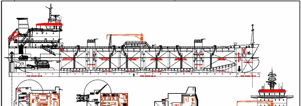
2 Figure 1 General View of the Ship Figure 2 General Arrangement
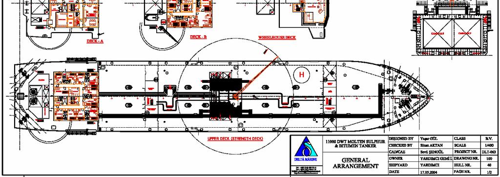
3 The aim of this work is to investigate the structural endurance of midship cargo area construction and internal cargo tanks of this sulphur tanker. Therefore, two finite element are developed to analyse the main and internal tank structural components, transverse and longitudinal corrugated bulkheads against the inertial internal pressure loading, maximum sea loading and test case loading in perspective of stress criteria and results are presented. MODELLING STAGE The structural finite element models of following three-cargo area with a pump room and internal cargo tank are developed for analyses. The extension of the model can be seen in Figure 3 below. Ansys 8.0 general purpose finite element software is used for all modelling, analysing and post-processing operations. Figure 3 Extension of the Finite Element Model Two finite element models are developed. The first model consists of only the three-cargo area and pump room to analyse main structure and the half model is developed by taking into account the symmetry feature along the longitudinal-vertical plane. The second model consists both of the main cargo areas, pump room and a internal tank structure to analyse internal tank and internal and main structure interaction. This model is fully developed with both port and starboard sides. The interaction between the internal tank and main structure is obtained by using the contact feature of Ansys software. The internal tank is restricted by contact elements as Ulepsi material in vertical direction, by the block structure placed at the centre longitudinal double bottom girder and deck girder in lateral direction and a block web frame in each cargo area restricts the internal tank in longitudinal direction. Block structures can be seen in solid model figures. Solid Modelling Stage The solid models are prepared in Ansys software and can be seen in Figures 3 to 6 below. In these Figures different colours indicate different thickness values and the detailed outputs of thickness values can be seen in Appendix I. In the definition stage of the thickness values, the deduction of corrosion additions are also taken into account according to BV Rules, Part B, Chapter 4, Section 2, [3] Table 2.


4 Figure 4 Solid Model of Main Structure Figure 5 Solid Model of Main Structure


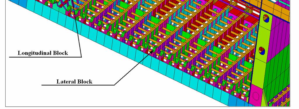
5 Figure 6 Solid Model of Internal Tank 2.2 Mesh Modelling Stage Ansys solid models are meshed by using the Ansys specific elements Shell63 and Contact52. Shell63 element is used for all plating parts, web frames and for HP profile s webs. Contact52 element is used as vertically contact material for interaction between the internal tank and main structure. The properties of these finite elements are given below. The first model, which consists of only the three-cargo area and pump room, is finely meshed because of the response of the main structure in scope of the analysis. Half of the ship is developed for this model by taking into account the symmetry feature along the longitudinalvertical plane. Details of the mesh density can be seen in Figures from 7 to 10. In the second model, which consists of both main cargo areas, pump room and an internal tank structure, only the internal tank is finely meshed because of the response of the internal tank structure in scope of the analysis. This model is fully developed with both port and starboard sides.


6 Figure 7 Mesh Density of the Main Structure Finite Element Model Figure 8 Main Structure Finite Element Model


")
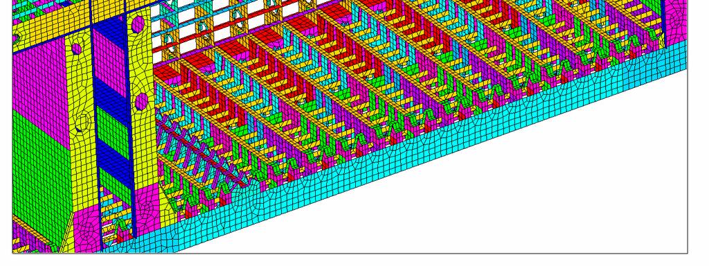
7 Figure 9 Finite Element Model with Internal Tank Figure 10 Finite Element Model with Internal Tank ( Main Structure has coarse mesh )
8 Material Properties The material for the steel used in the ship is St 42 grade shipbuilding steel and its properties are given below Elasticity modulus = N/mm2 Poission ratio = 0.30 Density = 7850 kg/m3 BOUNDARY & LOADING CONDITIONS Boundary Conditions For main structure finite element model; The nodes at the aft and fore end cross sections are coupled to section s centre nodes near to the natural axis and simple supported boundary conditions ( ux, uy, uz, Rx, Rz are fixed for aft end and uy and uz are fixed for fore end ) are applied. For the longitudinal-vertical centre plane, symmetry boundary conditions ( y, Rx,Rz ) are applied. For finite element model with internal tank; The nodes at the aft and fore end cross sections are coupled to section s centre nodes near to the natural axis and simple supported boundary conditions are applied. These centre nodes are also to be used to apply the global bending and wave induced moment values. Boundary conditions can be seen in Figure 11 below. Figure 11 Boundary Conditions For the Main Structure Finite Element Model
9 Loading Conditions It is aimed to get the worst loading condition for internal tank s transverse and longitudinal corrugated bulkhead structure, main structure web frames and girders. It is seen from the Table 1 which is obtained from pre-calculations, the load case b with the inertial internal pressure is the worst loading case for interaction between the internal tank and main structure, for ulepsi material, main structure web frames and internal tank bulkheads and girders. A+ loading case is worst loading case for longitudinal girders. Lateral and longitudinal accelerations are also important for the effects of internal tank over the main structure. Only the alternate loading condition is allowed during the voyage. But the unsymmetrical loading can be occur when the ship is in harbour. Table 1 Pressure values for load cases ( kn/m2 ) Therefore, Five different load cases are applied to the finite element models and the solutions obtained. These are; Load Case 1: Load Case b Load Case 2: Load Case a+ Load Case 3: Longitudinal Acceleration Case Load Case 4: Lateral Acceleration Case Load Case 5: Unsymmetrical Loading Load Case 1 Load Case b Load case b according to the BV Rules is applied to the model as alternate loading condition by assuming that it is worst case for main structure web frames and internal tank bulkheads and girders. In order to obtain alternate loading condition cargo tanks 4 and 5 which are in the middle cargo area are fully loaded according to the inertial pressure loading rules in Pt B, Ch 5, Sec with the liquid density of 1.8 t m, pressure set valve value of 0.17 bar, a X = m s and a Z = Load Case A+ A - B Internal Pressure at Internal Tank Bottom Sea Pressure at the Bottom m s. Sea pressures are applied according to the Pt B, Ch 5, Sec pressure for upright ship conditions. Wave pressure load case b is taken into account for this analysis as indicated in Pt B, Ch 5, Sec 4 2 Table 1. Hull girder moments are applied to the model according to the BV Pt B, Ch 7, App 1, Table 5 with the still water bending moment value of knm and vertical wave bending moment value of knm for sagging condition. Total bending moment is obtained by applying the difference between the total moment value and existing moment occurred by the loading on finite element model. Final total moment distribution can be seen Figure 12 below. Sea pressure load case and internal and sea pressure values can be seen in Figures 13 to 16
 Figure 12 Final Moment")

10 Moment ( knm ) Length ( mm ) Figure 12 Final Moment Distribution Along the Finite Element Model.Figure 13 Wave Pressure Distribution in Load Case b Figure 14 Internal Inertial Pressure Loading Values ( N/m2 )
")

11 Figure 15 Sea Pressure Loading Values ( N/m2 ) Figure 16 Pressure Loading Values on Deck ( N/m2 )
12 Load Case 2 Load Case a+ Load case a with positive h1 is applied to the model as alternate loading condition by assuming that it is worst case for empty tanks and longitudinal girders. In order to obtain alternate loading condition, cargo tanks 4 and 5 are fully loaded by using the liquid density of t m and pressure set valve value of 0.17 bar. Sea pressures are applied according to the Pt B, Ch 5, Sec pressure for upright ship conditions. Wave pressure load case a is taken into account for this analysis as indicated in Pt B, Ch 5, Sec 4 2 Table 1. Therefore, the worst loading case for empty tanks is obtained. Wave Pressure Distribution in Load Case a can be seen in Figure 17 below. Hull girder moments are applied to the model according to the BV Pt B, Ch 7, App 1, Table 5 with the still water bending moment value of knm and vertical wave bending moment value of knm for hogging condition. Total bending moment is obtained by applying the difference between the total moment value and existing moment occurred by the loading. Final total moment distribution can be seen Figure 18 below. Figure 17 Wave Pressure Distribution in Load Case a Moment ( knm ) Length ( mm ) Figure 18 Final Moment Distribution Along the Finite Element Model

 Figure 20 Sea Pressure Loading Values (")
13 Sea pressure load case and internal and sea pressure values can be seen in Figures 19 to 21. Figure 19 Internal Pressure Loading Values ( N/m2 ) Figure 20 Sea Pressure Loading Values ( N/m2 )


14 Figure 21 Pressure Loading Values on Deck ( N/m2 ) Load Case 3: Longitudinal Acceleration Case In this loading case, a longitudinal force value, which caused by maximum longitudinal acceleration value is applied to the longitudinal internal tank supports on the inner bottom by 2 distributing over the structure. The longitudinal acceleration is a X = m s. Distributed forces are 640 kn and 320 kn for 28 nodes at inner bottom supports and 2161 kn for 8 nodes at the deck. Details can be seen in Figure 22 and 23 below. No additional sea pressure, internal pressure and girder moments are applied because of only the longitudinal internal tank support structure is being investigated. Figure 22 Forces at the Inner Bottom Supports


15 Figure 23 Forces at the Deck Supports Load Case 4: Lateral Acceleration Case In this loading case, a lateral force value, which caused by maximum transverse acceleration value is applied to the lateral internal tank supports on inner bottom centre and deck centre by 2 distributing over the structure. The lateral acceleration is a Y = m s. Distributed forces are 257 kn for 27 nodes at the inner bottom. Details can be seen in Figure 24 below. No additional sea pressure, internal pressure and hull girder moments are applied because of only the lateral internal tank support structures are being investigated. Figure 24 Forces at the Inner Bottom Supports


16 Load Case 5: Unsymmetrical Loading In this loading case, unsymmetrical loading at the cargo 4 and 5 is taken into account. Although the unsymmetrical loading is not allowed during the voyage, it can be occur in the harbour condition when it is being loaded. Cargo tank 4 port side and cargo tank 5 starboard side is fully 3 loaded by using the liquid density of 1.8 t m and without the pressure set valve value. The pressure distribution can be seen in Figure 25. No additional sea pressure and hull girder moments are applied because of only the internal tank structure is being investigated. 4. ANALYSES & RESULTS 4.1 Structural Analysis Figure 25 Internal Pressure Loading Values ( N/m2 ) The solution strategy of the finite element models for load cases b and a+ is as explained below; First stage: Solution of the second model with the internal tank ( Internal tank is fine meshed and main structure coarse meshed ) by using the all internal and sea pressures and moment which are explained in load cases chapter. Internal tanks structure investigation is the objective this analysis. Second Stage: From the results of the first stage, obtain the vertical force values transmitted by Ulepsi materials from internal tank to main structure. Check these force values whether they are under the Ulepsi material force limit of 320 kn. In case of any exceeding force is obtained, by using a gap value between internal tank and Ulepsi material solve the first stage again and obtain the optimised solution.
17 Third stage: Solution of first finite element model, which consists only the finely meshed main structure. By applying the optimised force values transmitted by Ulepsi material to the main structure and the sea pressures and moments as explained in load cases chapter, obtain the results. Main structure investigation is the objective this analysis. As can be seen from the load cases, the worst case loading at the internal tanks and therefore at the Ulepsi material is obtained in Load Case b, which has maximum inertial internal pressures. Therefore the optimisation in the second analyse stage is only obtained for Load case b and the resulting gap values are used for the rest of the analyses. Results for the Load Case b and Load Case a+ are presented below. For the longitudinal and lateral acceleration loading cases the fine meshed finite element model is used and results are presented. In unsymmetrical loading case the second finite element model is used and the stress results at the internal tank structure are presented. Load Case 1 Resulting maximum stress values can be seen in Tables 1 to 5 below in MPa. Table 1 Stress Values at the Frames At the Middle of Tanks ( MPa ) Frame No Y Direction Stress Z Direction Stress YZ Shear Stress Von Mises Min Max Min Max Min Max Max
18 Table 2 Stress Values at the Longitudinal Girders ( MPa ) X Direction Stress Z Direction Stress XZ shear stress Von Mises Min Max Min Max Min Max Max Center Girder Middle Girder Inner Side Table 3 Stress Values at the Side Girders ( MPa ) X Direction Stress Y Direction Stress XY shear stress Von Mises Min Max Min Max Min Max Max 3400 mm mm mm Table 4 Stress Values at the Main Deck Plating ( MPa ) X Direction Stress Z Direction Stress Von Mises Min Max Min Max Max Table 5 Stress Values at the Hull Plating ( MPa ) X Direction Stress Y Direction Stress XY shear stress XZ shear stress Von Mises Min Max Min Max Min Max Min Max Max Von-Mises Results at the Frame 44 ( N/m2 )

19 YZ Shear Results at the Frame 44 Von-Mises Results at the Center Girder
20 X Direction Stress Results at the Center Girder XZ Shear Stress Results at the Center Girder

21 Von-Mises Stress Results at the Side Girder at 3400 mm from BL Von-Mises Stress Results at the Hull

22 Internal Tank Von-Mises Results at the Frame 59 Internal Tank Von-Mises Results at the Frame 63
23 Load Case 2 Von Mises Stress Results at Middle Girder ( N/m2 ) XZ Shear Stress Results at Middle Girder ( N/m2 )


24 Load Case 3 XZ Shear Stress Results at Side Girder ( N/m2 ) Von Mises Stress Values ( N/m2 )

")
25 Load Case 4 Von Mises Stress Values ( N/m2 ) Von Mises Stress Values ( N/m2 )


26 Load Case 5 Internal Tank Longitudinal Bulkhead Von Mises Stress Results ( N/m2 ) Internal Tank Longitudinal Bulkhead Z direction Stress Results ( N/m2 )