PRODUCT SPECIFICATION
|
|
|
- Roderick Bradley
- 5 years ago
- Views:
Transcription

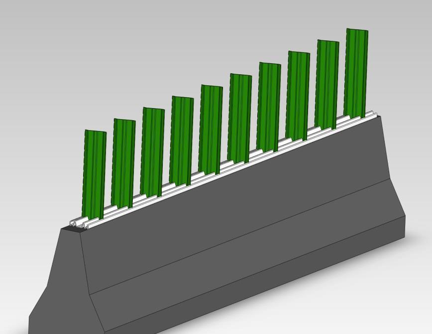
1 PRODUCT SPECIFICATION Part Name: PLASTICADE Modular Glare Screen System Description The Modular Glare Screen System is intended to be mounted to a barrier or median in order to delineate the barrier and provide a visual barrier to passing motorists. The Modular Glare Screen System shall be comprised of base rails and vertical blade components, which incorporates specific positioning to reduce glare. The base rail shall be secured to the top surface of the barrier, and vertical blades shall install in to the base rail in a manner such that no additional components, fasteners or tools are required. A glare screen system shall consist of multiple segments of rail/blade assemblies, as necessary, to cover any length median or barrier. The vertical blades shall snap into the base rail utilizing interlocking snap features integral to the rail and blades. The blades shall be capable of being installed into, and removed from, the base rail quickly and easily, while the rail is installed on the barrier. The vertical blades shall be installed into the rail by hand, with no additional connecting components, tools, or hardware required. Vertical blades shall be removable through the use of a single plastic tool, provided with the glare screen system. 1. Material The glare screen system shall be comprised of entirely non-metallic, impact resistant polymers, however fiber reinforced plastics or polymers shall not be used. Rail: White Color Blade: Green Color 2. General Dimensions / Configurations The base rail shall have a nominal width of 6 and a nominal height of 1.7. Base rails are available in standard lengths varying from 8 through 14. Refer to the included Plasticade drawing. Custom length and slot configurations are available. Vertical Blades shall have a nominal width of 6 and nominal thickness of.25. Vertical blade heights are available in standard heights, 18 through 24. Refer to included Plasticade drawing Custom heights are available. Form#: PS-TRAF-001 Page: 1 of 5
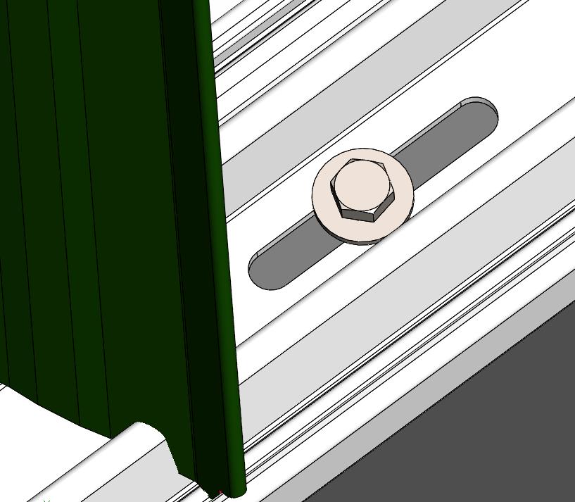
2 The angle of vertical blades relative to direction of traffic, and space between vertical blades, is shown on the included Plasticade drawing. In order to provide the anti-glare feature, blades are positioned at a 22 (±2 ) angle and they are spaced 14.5 inches apart O.C. For special circumstances that require closer spacing of blades, they may be mounted 7.25 inches apart upon special order. Standard Product is for use on left side of traffic. Custom design is available for use on right side of traffic. 3. Performance Impact Resistance The glare screen system shall have sufficient strength to withstand an impact to the blade, impact direction parallel to the base rail, of 150 joules. The impact shall be made with a 2 diameter circular slug at a minimum center distance of 10 from the bottom of the blade. Flexibility The blade shall sustain no breakage, cracking, or creasing after being bent over until contact is made between the base rail and top of the vertical blade. Temperature The glare screen system shall withstand impact and flexibility tests as specified above at temperatures of 0 ⁰F 120 ⁰F. 4. Installation The base rail shall have slotted holes throughout its length to be used for attachment of the glare screen system to the barrier. Decisions regarding appropriate hardware depend on the type of concrete barrier being used and any state requirements for pull strength, shear requirements, etc. These decisions need to be made by the agency or contractor who is actually installing the product. In cases where the specifications do not have specific requirements, Plasticade has recommended the use of a 3/8 x 2-1/4 Simpson Strong Tie Wedge Anchors combined with a 1-1/2 fender washer. Minimum of 1 anchor required per slot. Attachment hardware and method used to fasten glare screen to barrier should follow statespecific regulations where applicable, and is the responsibility of the agency or installer. Vertical blades shall be installed into slots in base rail by hand, using a tilt and lock method. Blades shall snap into the rail utilizing interlocking snap features integral to the rail and blades. No additional connecting components, tools, or hardware shall be necessary to install blades Form#: PS-TRAF-001 Page: 2 of 5


3 into base rail. The blades shall be capable of being installed into and removed from the base rail quickly and easily, while the rail is installed on the barrier. Vertical blades shall be removed from base rail with Plasticade plastic removal tool. 5. Regulatory Compliance Glare Screen system shall comply with applicable state and federal regulations. 6. Auxiliary Components Removal Tool 3/8 x 2-1/4 Wedge Anchor Simpson Strong Tie #WA Product Images Form#: PS-TRAF-001 Page: 3 of 5
4 Form#: PS-TRAF-001 Page: 4 of 5
5 Form#: PS-TRAF-001 Page: 5 of 5