Geotechnical Engineering Report
|
|
|
- Thomasine Singleton
- 5 years ago
- Views:
Transcription

1 Geotechnical Engineering Report Proposed Retaining Wall 44ARW-1 Interstate 235 between N.W. 50th Street and Interstate 44 Oklahoma City, Oklahoma May 8, 2014 Terracon Project No Prepared for: Leidos Engineering, LLC Oklahoma City, Oklahoma Prepared by: Terracon Consultants, Inc. Oklahoma City, Oklahoma
2
3 Geotechnical Engineering Report Proposed Retaining Wall 44ARW-1 Oklahoma City, Oklahoma May 8, 2014 Terracon Project No TABLE OF CONTENTS Page 1.0 INTRODUCTION PROJECT INFORMATION SUBSURFACE CONDITIONS Typical Subsurface Profile Groundwater ANALYSIS AND RECOMMENDATIONS Recommended Geotechnical Engineering Design Parameters Retaining Wall Stability Analyses Foundation Bearing Capacity Settlement of Reinforced Zone Direct Sliding Global Stability of Reinforced Zone Global Stability of Temporary Excavation Slopes Wall Drainage Recommendations Construction Considerations GENERAL COMMENTS APPENDIX A - FIELD EXPLORATION Exhibit A-1 Boring Location Diagram Exhibit A-2 Field Exploration Description Exhibit A-3 to A-6 Borings RW3-8, C-6, B-1, B-2, B-3 & B-4 APPENDIX B - LABORATORY TESTING Exhibit B-1 Exhibit B-2 Laboratory Test Description Grain Size Distribution Curves APPENDIX C - SUPPORTING DOCUMENTS Exhibit C-1 Exhibit C-2 Exhibit C-3 General Notes Unified Soil Classification System Sedimentary Rock Classification Responsive Resourceful Reliable
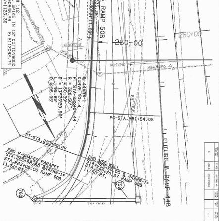
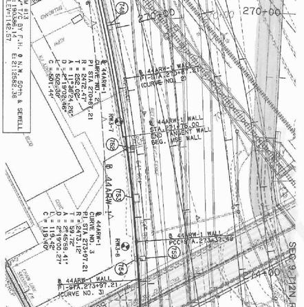
4 GEOTECHNICAL ENGINEERING REPORT PROPOSED RETAINING WALL 44ARW-1 INTERSTATE 235 BETWEEN N.W. 50TH STREET AND INTERSTATE 44 OKLAHOMA CITY, OKLAHOMA Terracon Project No May 8, INTRODUCTION This report presents the results of our geotechnical engineering services performed for the proposed retaining wall 44ARW-1 to be located on the east side of Interstate 235, from approximately 280 feet south of NW 50th Street extending north approximately 1,075 feet in Oklahoma City, Oklahoma. Exploration of the subsurface materials at the project site consisted of four additional borings (B-1 to B-4) taken to depths of approximately 10 to 15 feet. Subsurface information collected from borings RW3-8 and C-6 provided in our geotechnical report No dated 8/30/2011 and dated 4/15/2011 was also used in developing our recommendations. The purpose of these services is to provide information and geotechnical engineering recommendations relative to: subsurface soil conditions groundwater conditions design and construction of the MSE retaining wall 2.0 PROJECT INFORMATION The retaining wall will be a mechanically stabilized earth (MSE) wall located on Interstate 235 between Stations and The wall height will vary from about 12 to 35 feet and support a 4(H) or 3(H) to 1(V) slope above it comprised of natural soil/rock, and additional or existing fill. The wall location is currently covered with vegetation and existing grades vary from about El to El Grades in front of the wall will vary from El to El Based on the boring elevations and preliminary wall profile provided, we anticipate up to 33 feet of cut will be necessary to construct the retaining wall and lower the existing grades for the proposed I-235 northbound lane. The wall will be designed and constructed based on a contractor supplied design. We anticipate that the wall will be constructed with either a modular block facing or panel facing with either extensible or in extensible earth reinforcement. Responsive Resourceful Reliable 1
5 Geotechnical Engineering Report Proposed Retaining Wall 44ARW-1 Oklahoma City, Oklahoma May 8, 2014 Terracon Project No SUBSURFACE CONDITIONS 3.1 Typical Subsurface Profile Specific conditions encountered at each boring location are indicated on the individual bor ing logs. Stratification boundaries on the boring logs represent the approximate location of changes in soil types; in-situ, the transition between materials may be gradual. Details for each of the borings can be found on the boring logs included in Appendix A of this report. Based on the results of the borings, subsurface conditions on the project site can be generalized as follows: Subsurface conditions along the I ARW-1 can be divided into two categories, those areas that encountered deep fill materials over weathered bedrock (borings RW3-8 and C-6) south of N.W. 50th Street, and those that encountered native soils over shallow weathered bedrock (borings B-1, B-2, B-3 and B-4) north of N.W. 50th Street. Description 1. Stratum 1a Stratum 1b Stratum 2 Approximate Depth to Bottom of Stratum (feet) 36.5 to 40 (borings RW3-8 and C-6) 2 to 13.5 (borings B-1 to B-4) 40 to 53.5 (borings RW3-8 and C-6) Material Encountered Fill: Lean to fat clay with varying amounts of sand 1 Fill: Sand with varying amounts of clay, silt and gravel 1 Sand with varying amounts of silt and clay Lean clay with varying amounts of sand Consistency/Density N/A Loose to medium dense Stiff to very stiff Highly weathered to weathered Soft to moderately hard shale Stratum 3 Underlying stratum Highly weathered to weathered Poorly cemented to well sandstone cemented The existing fill may have been placed during the construction of the existing roadway. We are not aware that compaction testing was performed during placement of the fill. The depth, composition and compaction of the existing fill materials can vary greatly over relatively small lateral and vertical distances. Because of the potential variability of fill, it will not be possible to accurately predict the amount of fill that may need to be removed and replaced to develop suitable support for the proposed improvements until site grading is underway. The depth and composition of the fill, observed at the discrete boring locations, should only be used for estimating purposes. Laboratory tests were conducted on selected soil samples and the test results are presented on the boring logs in Appendix A and on test report forms in Appendix B. Responsive Resourceful Reliable 2
6 Geotechnical Engineering Report Proposed Retaining Wall 44ARW-1 Oklahoma City, Oklahoma May 8, 2014 Terracon Project No Groundwater The borings were monitored while drilling, immediately after completing the drilling activities and at least 24 hours after boring completion for the presence and level of groundwater. At these times, groundwater was observed at the following depths: Boring Number Depth (ft.) While Drilling Elevation (ft.) Immediately After Drilling Depth (ft.) Elevation (ft.) 24+ Hour Water Level After Drilling Depth (ft.) Elevation (ft.) RW C-6 Not measured Not measured Not measured Not measured Not measured Not measured B B-2 B-3 B-4 Not encountered Not encountered Not encountered Not measured Not measured Not measured Not encountered Not encountered Not encountered Not measured Not measured Not measured To obtain more accurate groundwater level information, longer observations in a monitoring well or piezometer that is sealed from the influence of surface water would be needed. Fluctuations in groundwater levels can occur due to seasonal variations in the amount of rainfall, runoff, altered natural drainage paths, and other factors not evident at the time the borings were advanced. Consequently, the designer and contractor should be aware of this possibility while designing and constructing this project. 4.0 ANALYSIS AND RECOMMENDATIONS Based on the results of our exploration, the following geotechnical considerations were identified: Boring RW3-8: Sta to Sta This boring indicates the presence of fill extending to a depth of about 36.5 feet below existing ground. Based on the information provided, it appears that the wall may bear on existing fill. Global stability and bearing capacity analysis indicate relatively long reinforcement lengths when the groundwater is considered at the base of the proposed retaining wall within the fill. Responsive Resourceful Reliable 3
7 Geotechnical Engineering Report Proposed Retaining Wall 44ARW-1 Oklahoma City, Oklahoma May 8, 2014 Terracon Project No Boring C-6: Sta to Sta Based on the retaining wall profile provided by Leidos Engineering, Inc., the wall will extend through the fill, and will apparently bear on the native lean clay. Borings B-1, B-2 and B-3: Sta to Sta The wall will extend through the native soils, and will apparently bear on the weathered sandstone or highly weathered shale/sandstone. Boring B-4: Sta to Sta The wall will extend through the native soil, and will apparently bear on the weathered sandstone. Due to the uncertainty of the existing fill, we believe that the fill with debris encountered in boring RW3-8 could be present at other locations along the wall alignment. Undercut and replacement of the fill with debris will be required in order to reduce reinforcement lengths and expected differential settlement within the wall alignment. We understand that the wall will ultimately be designed using the AASHTO Load and Resistance Factor Design (LFRD) method. Recommended design parameters and the results of our preliminary analyses using these values are provided in the following sections of this report. 4.1 Recommended Geotechnical Engineering Design Parameters In our analyses, we considered the soils outside the reinforced zone would partially consist of existing overburden soils/rock and fill materials similar to the on-site soils/rock encountered in the soil test borings. We also assumed that the backfill used within the reinforcement zone will consist of properly compacted ODOT Type A aggregate base material or backfill meeting current AASHTO and ODOT Standards for MSE retaining walls. Based on our analyses of the laboratory tests performed for this project and our experience with similar soils, we recommend the following geotechnical design parameters be used for analysis and design of the wall per AASHTO LRFD Bridge Design Specification, 5th Edition, RECOMMENDED GEOTECHNICAL PARAMETERS FOR MSE WALL DESIGN Material Type Reinforced Zone (ODOT Type A ) Total Unit Weight (pcf) 1 Effective Stress (Drained) c, psf Parameters 1, degrees 125 N/A 2 34 Alternate 110 N/A 34 Responsive Resourceful Reliable 4
8 Geotechnical Engineering Report Proposed Retaining Wall 44ARW-1 Oklahoma City, Oklahoma May 8, 2014 Terracon Project No RECOMMENDED GEOTECHNICAL PARAMETERS FOR MSE WALL DESIGN Material Type Reinforced Zone (ASTM C-33 #57 Stone) Retained/Foundation Zone Total Unit Weight (pcf) 1 Effective Stress (Drained) c, psf Parameters 1, degrees (Fill: Lean clay or clayey sand) (near RW3-8 & C-6) 3 Foundation Zone (lean clay) (near C-6) Foundation Zone (Weathered Sandstone) (B-1 to B-4) The geotechnical parameters provided for the foundation soil are based on average correlated values. 2. C=2000 psf used for global analysis to represent grid strength and force potential failure planes outside of the reinforced zone. 3. Due to the presence of fill near the bearing level at borings RW3-8 and C-6, we recommend overexcavating the subgrade within the proposed retaining wall areas to a depth of about 3 feet below the retaining wall foundation. The overexcavation should extend laterally a minimum of 5 feet beyond the front of the retaining wall toe to a minimum distance behind the wall facing equal to the width of the reinforced zone. The overexcavation should be backfilled to the foundation base elevation with approved ODOT Type A structural fill placed in lifts of 9 inches or less in loose thickness and should be compacted to at least 98 percent of the material s maximum standard Proctor dry density (AASHTO T-99) within 2 percent of its optimum value. Based on the subsurface conditions encountered in the soil test borings, listed below are the resistance and load factors based on AASHTO s LRFD Bridge Design Specification, 5 th Edition, 2010 that should be used by the retaining wall designer in the design of the retaining wall. Load Factor for vertical earth pressure, EV, from Table and Figure C : Sliding and Eccentricity p-ev = 1.00 Bearing Capacity p-ev = 1.35 Load Factor for live load surcharge, LS, from Table and Figure C b: Bearing Capacity, Sliding and Eccentricity p-ev = 1.75 Responsive Resourceful Reliable 5
9 Geotechnical Engineering Report Proposed Retaining Wall 44ARW-1 Oklahoma City, Oklahoma May 8, 2014 Terracon Project No Load factor for active earth pressure, EH, from Table and Figure C : p-eh = 1.50 Resistance factor for shear resistance along common interfaces from table : Reinforced Soil and Foundation = 0.9 Resistance factor for bearing capacity of a shallow foundation from table : b = 0.45 Please note that we have determined reinforcement lengths for the MSE wall based on our experience with MSE wall design and the parameters listed in the report. Actual design embedment lengths in the contractor supplied design could vary from those used in our analyses. 4.2 Retaining Wall Stability Analyses Based on the plans, profiles, and cross sections provided by Leidos Engineering, Inc., we have analyzed four different cross sections of the anticipated design profile of the retaining wall. The cross sections were taken at stations , , and The maximum design wall height will be up to about 35 feet. We understand that the retaining wall contractor will perform internal and external stability analyses as part of the contractor supplied design of the wall. Our engineering analyses of the MSE wall has considered the following: Foundation bearing capacity (with water level at the base of the foundation) Settlement of the reinforced zone and differential settlement along the wall fascia Direct sliding at the base of the reinforced zone Horizontal grade at the toe of the proposed wall 4H:1V and 3H:1V grade at the back of the proposed wall Minimum wall embedment of 3 feet Global stability of the reinforced zone for both circular and horizontal block slip surfaces, considering the reinforced zone to act as a rigid block Reinforcement will consist of extensible geogrid Foundation Bearing Capacity The factored bearing resistance q R was evaluated using the following equation, which is dependent on various soil properties and the design grid length. Responsive Resourceful Reliable 6
10 Geotechnical Engineering Report Proposed Retaining Wall 44ARW-1 Oklahoma City, Oklahoma May 8, 2014 Terracon Project No q R = b q n (Equation AASHTO ) where: b = resistance factor q n = nominal bearing resistance, which is defined as q n = c N cm B N m C w where: c = cohesion = unit weight N cm and N = dimensionless bearing capacity coefficients B = total length of reinforcement C w = correction factors to account for the location of groundwater table Based on the subsurface conditions encountered in the soil test borings and the proposed wall geometry, the reinforcement grid lengths required varied from 11 to 45 feet (about 73 to 130 percent) in order to satisfy the LRFD Capacity to Demand Ratio (CDR). It is important to note that for our analyses, we have considered that the ground water level will affect the ultimate bearing capacity of the foundation soils. This assumption was made based on the 24 hour water level readings and the geometry of the analyses. We also assumed that the wall near boring RW3-8 will bear on approximately 5 feet of the remaining existing fill. Based on the subsurface conditions, the retaining wall foundation can be analyzed using the geotechnical design parameters presented in the Recommended Geotechnical Design Parameters section of this report Settlement of Reinforced Zone The wall settlement will depend upon the variations within the subsurface soil profile, the structural loading conditions and the quality of the past and future earthwork operations. Because of the variations associated with these parameters, Terracon cannot accurately estimate settlements under all design scenarios. Assuming that the foundation bearing conditions are similar to our subsurface data beneath all sections of the wall, it is our opinion that the maximum total settlement experienced along the retaining wall will be less than 1 inch with maximum differential settlements not expected to exceed a slope of 1:200. These values should be evaluated by the wall designer/manufacturer to confirm that the wall will be able to tolerate this magnitude of total and differential settlement Direct Sliding Our analyses indicate that with reinforcement lengths required to meet bearing capacity and global stability requirements (on the order of 73 to 130 percent of the wall height) have a CDR against direct sliding at the foundation equal to or greater than 1.0. Sliding may control the design where the bearing surface consists of bedrock (shale or sandstone) support, Responsive Resourceful Reliable 7
11 Geotechnical Engineering Report Proposed Retaining Wall 44ARW-1 Oklahoma City, Oklahoma May 8, 2014 Terracon Project No such as near borings B-1, B-2, B-3 and B-4. The factored resistance against failure by sliding was determined using the following equation. R R = R (Equation AASHTO ) where: = resistance factor for shear resistance between soil and foundation R = nominal sliding resistance between soil and foundation Based on the subsurface conditions, the wall designer should use the geotechnical design parameters presented in the Recommended Geotechnical Design Parameters section of this report when analyzing the external sliding resistance Global Stability of Reinforced Zone We have performed global stability analyses for conceptual wall sections at borings RW3-8, C- 6, B-2 and B-4. Drained soil, foundation, and backfill geotechnical parameters were used in our analyses. A resistance factor,, of 0.65, as outlined in section of AASHTO s LRFD Bridge design Specification, 5 th Edition, 2010 was applied when analyzing the global stability. Circular failures were analyzed using the modified Bishop method and sliding block failures were analyzed using the modified Janbu method. All global stability analyses indicated a CDR of 1.0 or greater. We constrained the analysis of sliding block slip surfaces to the interface between the reinforced zone and upper portion of the foundation soils by limiting shear surface development in the reinforced zone. Our analysis focused on developing the minimum reinforced zone that would satisfy a minimum global stability CDR of 1.0. The stability analyses were performed on wall sections with reinforced zone length-to-height ratio (i.e., the ratio of length of the reinforced zone to total wall height) of 0.7 to 1.3 as determined to meet bearing capacity or sliding requirements. If the wall geometry is changed (deeper penetration, shorter grids, etc), then additional global stability analyses should be performed to confirm that the CDR is greater than 1.0. Please note that the preceding discussion related so external global stability and not compound stability of the retaining wall. Compound stability should be considered in the design analysis conducted by the wall design engineer. 4.3 Global Stability of Temporary Excavation Slopes Based on the drawings provided by Leidos Engineering, Inc., it is anticipated that up to 35 feet of cut will be required for constructing the retaining wall. A slope stability analysis was Responsive Resourceful Reliable 8
12 Geotechnical Engineering Report Proposed Retaining Wall 44ARW-1 Oklahoma City, Oklahoma May 8, 2014 Terracon Project No conducted for a typical section for temporary construction excavations. We have assumed no surcharge in our analysis for these excavations. A resistance factor,, of 0.75, as outlined in section of AASHTO s LRFD Bridge design Specification, 5 th Edition, 2010 was applied when analyzing the global stability for maximum temporary excavation slopes. Excavations deeper than 4 feet should meet all OSHA and other applicable safety regulations. Slopes for temporary excavations for subsurface conditions similar to those encountered at this project should be constructed at 3H:1V or flatter. In areas where weathered bedrock is encountered, the slopes for temporary excavation on weathered bedrock could be steepened to 2H:1V. We anticipate that excavations for the retaining wall may extend into weathered bedrock. Rock formations that have standard penetration test results of 4 or more inches per 50 blows can usually be excavated with heavy excavation equipment equipped with ripping teeth. Rock formations that have standard penetration test results of 3 inches or less per 50 blows usually require either pneumatic equipment or blasting for rock break-up and removal. However, variations in hardness of rock can occur with depth and distance from the borings. 4.4 Wall Drainage Recommendations Care should be taken in the design and during construction to develop and maintain rapid, positive drainage away from the retaining wall area. Water should not be allowed to pond adjacent to either the upslope or downslope sides of the retaining wall. We recommend that drainage swales with sufficient gradients be constructed along both the upslope and downslope sides of the wall to direct surface water away from the wall. Proper surface drainage is needed to prevent water from flowing over the face of the wall and saturating either the fill behin d the wall or the subgrade soils at the base of the wall. If Oklahoma Department of Transportation (ODOT) Type A aggregate base material is used to construct the reinforced zone, we recommend that a backslope drain, comprised of a geocomposite drainage blanket, such as Miradrain, be attached to the face of the cut backslope and extend down to a collector drain pipe placed along the bottom of the reinforced zone at the base of the cut slope. The collector drain should consist of a perforated PVC pipe that is placed in free-draining aggregate such as ASTM No. 57 stone, with the stone wrapped in a geotextile filter fabric. The collector drain should be sloped to drain out beyond one or both ends of the retaining wall. The geocomposite drainage blanket should be cut off at a depth of 2 feet below the finished ground surface at the back of the reinforced backfill zone to allow a minimum cover of 2 feet of compacted clayey soil over the drain to prevent the infiltration of surface water into the backslope drain. Responsive Resourceful Reliable 9
13 Geotechnical Engineering Report Proposed Retaining Wall 44ARW-1 Oklahoma City, Oklahoma May 8, 2014 Terracon Project No Alternatively, select drainable aggregate fill material consisting of crushed No. 57 stone could be imported to construct the entire reinforced zone. If the crushed No. 57 stone is used to construct the reinforced backfill zone, we recommend that a geotextile filter fabric, such as Mirafi 140N be placed between the face of the retained soil and the reinforced backfill zone to prevent the migration of fines from the native soils or proposed fill into the free-draining No. 57 stone. 4.5 Construction Considerations The construction specifications should provide the backfill material specifications and design strength parameters that are required for the different fill zones so that unsuitable materials are not used in the reinforced backfill zone during construction. We recommend that any fill with debris encountered at the time of construction be removed and replaced with ODOT Type A structural fill. Any overexcavations for compacted backfill placement below the retaining wall should extend laterally a minimum of 5 feet beyond the front of the retaining wall (or edge of the embankment) toe to a minimum distance behind the wall facing equal to the width of the reinforced zone. The overexcavation should then be backfilled to the foundation base elevation with approved ODOT Type A structural fill placed in lifts of 9 inches or less in loose thickness and compacted to at least 98 percent of the material's maximum standard Proctor dry density (ASTM D-698) at a moisture content between 2 percent below to 2 percent above the material s optimum moisture content. Prior to starting construction of the MSE wall, fill material proposed to be used in constructing the reinforced zone for the wall should be sampled and tested in the laboratory to confirm that the engineering properties of the backfill satisfy the specified properties used in design. Observation and field testing during construction of the MSE wall by qualified geotechnical personnel is also recommended. We anticipate that excavations for the retaining wall will extend into weathered bedrock. Rock formations that have standard penetration test results of 4 or more inches per 50 blows can usually be excavated with heavy excavation equipment equipped with ripping teeth. Rock formations that have standard penetration test results of 3 inches or less per 50 blows usually require either pneumatic equipment or blasting to remove. However, variations in hardness of rock can occur with depth and distance from the borings. Based on the groundwater conditions encountered during our subsurface exploration, excavations for the retaining wall may encounter groundwater. Therefore, the contractor should anticipate dewatering will be required during the construction of the walls. Responsive Resourceful Reliable 10
14 Geotechnical Engineering Report Proposed Retaining Wall 44ARW-1 Oklahoma City, Oklahoma May 8, 2014 Terracon Project No GENERAL COMMENTS Terracon should be retained to review the final design plans and specifications so comments can be made regarding interpretation and implementation of our geotechnical recommendations in the design and specifications. Terracon also should be retained to provide observation and testing services during grading, excavation, wall construction and other earth-related construction phases of the project. The analysis and recommendations presented in this report are based upon the data obtained from the borings performed at the indicated locations and from other information discussed in this report. This report does not reflect variations that may occur between borings, across the site, or due to the modifying effects of construction or weather. The nature and extent of such variations may not become evident until during or after construction. If variations appear, we should be immediately notified so that further evaluation and supplemental recommendations can be provided. The scope of services for this project does not include either specifically or by implication any environmental or biological (e.g., mold, fungi, bacteria) assessment of the site or identification or prevention of pollutants, hazardous materials or conditions. If the owner is concerned about the potential for such contamination or pollution, other studies should be undertaken. This report has been prepared for the exclusive use of our client for specific application to the project discussed and has been prepared in accordance with generally accepted geotechnical engineering practices. No warranties, either express or implied, are intended or made. Site safety, excavation support, and dewatering requirements are the responsibility of others. In the event that changes in the nature, design, or location of the project as outlined in this report are planned, the conclusions and recommendations contained in this report shall not be considered valid unless Terracon reviews the changes and either verifies or modifies the conclusions of this report in writing. Responsive Resourceful Reliable 11
15 APPENDIX A FIELD EXPLORATION

16
17 Geotechnical Engineering Report Proposed Retaining Wall 44ARW-1 Oklahoma City, Oklahoma May 8, 2014 Terracon Project No Field Exploration Description A total of four additional test borings were drilled at the site on April 2, The borings were drilled to depths ranging from approximately 10 to 15 feet below the ground surface at the approximate locations shown on the attached Boring Location Diagram, Exhibit A-1. Subsurface information collected from borings RW3-8 and C-6 provided in our geotechnical report No s dated 8/30/2011 and dated 4/15/2011 was also used in developing our recommendations. Terracon personnel located the borings in the field by taping distances and estimating right angles based on information from the site plan provided by Leidos Engineering, LLC. The boring locations should be considered accurate only to the degree implied by the methods used to define them. Terracon determined the approximate ground surface elevations at the borings using an engineer s level. These elevations were referenced to the benchmark shown in the following table. Based on the benchmark, the ground surface elevations at the boring locations ranged from to feet. The elevations shown on the logs have been rounded to the nearest 0.1 foot. The boring locations and elevations should be considered accurate only to the degree implied by the methods used to define them. Bench Mark Description Northing/Easting Elevation, ft. 13 V T/C by N.W. 50th & Sewell / An all-terrain truck mounted, rotary drill rig equipped with continuous flight augers was used to advance the boreholes. Representative samples were obtained by the split-barrel sampling procedures. The split-barrel sampling procedure uses a standard 2-inch O.D. split-barrel sampling spoon that is driven into the bottom of the boring with a 140-pound drive hammer falling 30 inches. The number of blows required to advance the sampling spoon the last 12 inches, or less, of a typical 18-inch sampling interval or portion thereof, is recorded as the standard penetration resistance value, N. The N value is used to estimate the in-situ relative density of cohesionless soils and, to a lesser degree of accuracy, the consistency of cohesive soils and the hardness of sedimentary bedrock. The sampling depths, penetration distances, and the N values are reported on the boring logs. The samples were tagged for identification, sealed to reduce moisture loss and returned to the laboratory for further examination, testing and classification. An automatic Standard Penetration Test (SPT) drive hammer was used to advance the split - barrel sampler. The automatic drive hammer achieves a greater mechanical efficiency when compared to a conventional safety drive hammer operated with a cathead and rope. We considered this higher efficiency in our interpretation and analysis of the subsurface information provided with this report. Responsive Resourceful Reliable Exhibit A-2
18 Geotechnical Engineering Report Proposed Retaining Wall 44ARW-1 Oklahoma City, Oklahoma May 8, 2014 Terracon Project No The drill crew prepared field logs as part of the drilling operations. These boring logs included visual classifications of the materials encountered during drilling and the driller s interpretation of the subsurface conditions between samples. The final boring logs included with this report represent the engineer s interpretation of the field logs and include modifications based on observations and tests of the samples in the laboratory. As required by the Oklahoma Water Resources Board, any borings deeper than 20 feet, or borings that encounter groundwater or contaminated materials must be grouted or plugged in accordance with Oklahoma State statutes. One boring log must also be submitted to the Oklahoma Water Resources Board for each 10 acres of project site area. Terracon grouted the borings and submitted a log in order to comply with the Oklahoma Water Resources Board requirements. Responsive Resourceful Reliable Exhibit A-2
19
20
21
22
23
24
25
26
27
28
29
30 APPENDIX B LABORATORY TESTING
31 Geotechnical Engineering Report Proposed Retaining Wall 44ARW-1 Oklahoma City, Oklahoma May 8, 2014 Terracon Project No Laboratory Testing Samples retrieved during the field exploration were taken to the laboratory for further observation by the project geotechnical engineer and were classified in accordance with the Unified Soil Classification System (USCS) described in Appendix C. Samples of bedrock were classified in accordance with the general notes for Sedimentary Rock Classification. At that time, the field descriptions were confirmed or modified as necessary and an applicable laboratory testing program was formulated to determine engineering properties of the subsurface materials. Laboratory tests were conducted on selected soil and bedrock samples and the test results are presented in this appendix. The laboratory test results were used for the geotechnical engineering analyses, and the development of foundation and earthwork recommendations. Laboratory tests were performed in general accordance with the applicable ASTM, local or other accepted standards. Selected soil and bedrock samples obtained from the site were tested for the following engineering properties: In-situ Water Content Atterberg Limits Sieve Analysis Responsive Resourceful Reliable Exhibit B-1
32
33 APPENDIX C SUPPORTING DOCUMENTS
34 DESCRIPTION OF SYMBOLS AND ABBREVIATIONS GENERAL NOTES Water Initially Encountered (HP) Hand Penetrometer Auger Split Spoon Water Level After a Specified Period of Time (T) Torvane SAMPLING Shelby Tube Texas Cone Grab Sample Pressure Meter Rock Core No Recovery WATER LEVEL Water Level After a Specified Period of Time Water levels indicated on the soil boring logs are the levels measured in the borehole at the times indicated. Groundwater level variations will occur over time. In low permeability soils, accurate determination of groundwater levels is not possible with short term water level observations. FIELD TESTS (b/f) (PID) (OVA) (TCP) Standard Penetration Test (blows per foot) Photo-Ionization Detector Organic Vapor Analyzer Texas Cone Penetrometer DESCRIPTIVE SOIL CLASSIFICATION Soil classification is based on the Unified Soil Classification System. Coarse Grained Soils have more than 50% of their dry weight retained on a #200 sieve; their principal descriptors are: boulders, cobbles, gravel or sand. Fine Grained Soils have less than 50% of their dry weight retained on a #200 sieve; they are principally described as clays if they are plastic, and silts if they are slightly plastic or non-plastic. Major constituents may be added as modifiers and minor constituents may be added according to the relative proportions based on grain size. In addition to gradation, coarse-grained soils are defined on the basis of their in-place relative density and fine-grained soils on the basis of their consistency. LOCATION AND ELEVATION NOTES Unless otherwise noted, Latitude and Longitude are approximately determined using a hand-held GPS device. The accuracy of such devices is variable. Surface elevation data annotated with +/- indicates that no actual topographical survey was conducted to confirm the surface elevation. Instead, the surface elevation was approximately determined from topographic maps of the area. RELATIVE DENSITY OF COARSE-GRAINED SOILS (More than 50% retained on No. 200 sieve.) Density determined by Standard Penetration Resistance Includes gravels, sands and silts. CONSISTENCY OF FINE-GRAINED SOILS (50% or more passing the No. 200 sieve.) Consistency determined by laboratory shear strength testing, field visual-manual procedures or standard penetration resistance STRENGTH TERMS Descriptive Term (Density) Loose Medium Dense Dense Standard Penetration or N-Value Blows/Ft. Ring Sampler Blows/Ft. Descriptive Term (Consistency) Very Loose Very Soft Standard Penetration or N-Value Blows/Ft. Ring Sampler Blows/Ft. 0-1 < Soft 500 to 1, Stiff Unconfined Compressive Strength, Qu, psf less than 500 Medium-Stiff 1,000 to 2, ,000 to 4, Very Dense > 50 > _ 99 Very Stiff 4,000 to 8, Hard > 8,000 > 30 > 42 RELATIVE PROPORTIONS OF SAND AND GRAVEL Descriptive Term(s) of other constituents Percent of Dry Weight Major Component of Sample GRAIN SIZE TERMINOLOGY Particle Size Trace With Modifier < > 30 Boulders Cobbles Gravel Sand Silt or Clay Over 12 in. (300 mm) 12 in. to 3 in. (300mm to 75mm) 3 in. to #4 sieve (75mm to 4.75 mm) #4 to #200 sieve (4.75mm to 0.075mm Passing #200 sieve (0.075mm) RELATIVE PROPORTIONS OF FINES Descriptive Term(s) of other constituents Trace With Modifier Percent of Dry Weight < > 12 Term Non-plastic Low Medium High PLASTICITY DESCRIPTION Plasticity Index > 30 Exhibit C-1
35 UNIFIED SOIL CLASSIFICATION SYSTEM Criteria for Assigning Group Symbols and Group Names Using Laboratory Tests A Coarse Grained Soils: More than 50% retained on No. 200 sieve Fine-Grained Soils: 50% or more passes the No. 200 sieve Gravels: More than 50% of coarse fraction retained on No. 4 sieve Sands: 50% or more of coarse fraction passes No. 4 sieve Silts and Clays: Liquid limit less than 50 Silts and Clays: Liquid limit 50 or more Group Symbol Soil Classification Group Name B Clean Gravels: Cu 4 and 1 Cc 3 E GW Well-graded gravel F Less than 5% fines C Cu 4 and/or 1 Cc 3 E GP Poorly graded gravel F Gravels with Fines: Fines classify as ML or MH GM Silty gravel F,G,H More than 12% fines C Fines classify as CL or CH GC Clayey gravel F,G,H Clean Sands: Cu 6 and 1 Cc 3 E SW Well-graded sand I Less than 5% fines D Cu 6 and/or 1 Cc 3 E SP Poorly graded sand I Sands with Fines: Fines classify as ML or MH SM Silty sand G,H,I More than 12% fines D Fines classify as CL or CH SC Clayey sand G,H,I Inorganic: Organic: Inorganic: Organic: PI 7 and plots on or above A line J CL Lean clay K,L,M PI 4 or plots below A line J ML Silt K,L,M Liquid limit - oven dried Liquid limit - not dried 0.75 OL Organic clay K,L,M,N Organic silt K,L,M,O PI plots on or above A line CH Fat clay K,L,M PI plots below A line MH Elastic Silt K,L,M Liquid limit - oven dried Liquid limit - not dried Highly organic soils: Primarily organic matter, dark in color, and organic odor PT Peat 0.75 OH Organic clay K,L,M,P Organic silt K,L,M,Q A Based on the material passing the 3-inch (75-mm) sieve B If field sample contained cobbles or boulders, or both, add with cobbles or boulders, or both to group name. C Gravels with 5 to 12% fines require dual symbols: GW-GM well-graded gravel with silt, GW-GC well-graded gravel with clay, GP-GM poorly graded gravel with silt, GP-GC poorly graded gravel with clay. D Sands with 5 to 12% fines require dual symbols: SW-SM well-graded sand with silt, SW-SC well-graded sand with clay, SP-SM poorly graded sand with silt, SP-SC poorly graded sand with clay E Cu = D 60 /D 10 Cc = D (D 10 2 ) 30 x D 60 F If soil contains 15% sand, add with sand to group name. G If fines classify as CL-ML, use dual symbol GC-GM, or SC-SM. H If fines are organic, add with organic fines to group name. I If soil contains 15% gravel, add with gravel to group name. J If Atterberg limits plot in shaded area, soil is a CL-ML, silty clay. K If soil contains 15 to 29% plus No. 200, add with sand or with gravel, whichever is predominant. L If soil contains 30% plus No. 200 predominantly sand, add sandy to group name. M If soil contains 30% plus No. 200, predominantly gravel, add gravelly to group name. N PI 4 and plots on or above A line. O PI 4 or plots below A line. P PI plots on or above A line. Q PI plots below A line. Exhibit C-2
36 Exhibit C-3