Cable Stay Replacement and Deck Rehabilitation of I-310 Luling - Hale Boggs Mississippi River Bridge
|
|
|
- Ambrose Palmer
- 5 years ago
- Views:
Transcription
1 Cable Stay Replacement and Deck Rehabilitation of I-310 Luling - Hale Boggs Mississippi River Bridge AASHTO SCOBS ANNUAL MEETING SPOKANE, WA JUNE 15, 2017 Paul Fossier, P.E. Bridge Design Engineer Administrator Louisiana Department of Transportation and Development (LA DOTD)

2


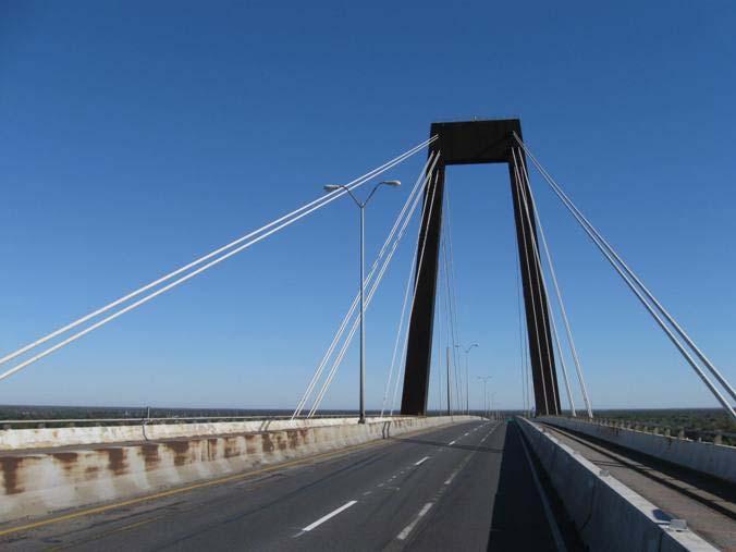
3 Opened in 1983, 1222 FT. MAIN SPAN, STEEL ORTHOTROPIC DECK, STEEL BOX GIRDERS, STEEL TOWERS, WEATHERING STEEL, 72 CABLES IN GROUPS OF 2 OR 4

4

5

6
7 Statement of Problem Rusting and water leakage in anchorages Cracking/splitting of cable cover pipes Signs of compromise in cables safety Wind-rain cable vibration issues Wearing surface over steel deck has reached its service life. LADOTD initiated a project for Structural Evaluation of the Stay Cables


8 Old Stay Cables Parallel Wire System


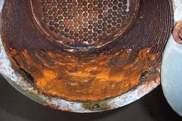
9 Lower Anchorage


10 Upper Anchorage
11 Inspection, Condition Rating, and Life-Cycle-Cost Analysis

 Cable Force Measurement Difference between design and")
12 Assessment of Overall Integrity NE I - TE NE I - TW NE I - BE NE I - BW NE II - T NE II - B NE III - T NE III - B NE IV - TE NE IV - TW NE IV - BE NE IV - BW NE V - TE NE V - TW NE V - BE NE V - BW NE VI - T NE VI - B Measured Force Design Force Force (Kips) Cable Force Measurement Difference between design and measured profile

13 Anchorage Inspection


14 Cable Free Length Inspection
15 Inspection findings Damage Severity Levels Severity Level Status Description 1 Satisfactory Minor deterioration and anomalies noted 2 Poor Deterioration of the protective elements and potential for degradation. Cables with this level of damages need to be routinely monitored and corrective action needs to be planned. 3 Critical Deterioration or potential for deterioration of the main tension elements (steel wires) exists. Action (repair) is necessary. Cables with this level of damages shall be closely monitored until repairs are applied.


16 Severity Level 3 - Critical, Damage Examples
17 Summary 40 out of 72 cables were rated critical All cables had at least damage Level 2 Increasing rate of deterioration was evident Timely corrective action was needed Based on a Life-Cycle-Cost Analysis, public safety concerns, and importance of the bridge, LADOTD decided to replace all cables
18 Cable Replacement Design, and Construction
19 Cable Replacement Design Objectives: Develop a cost effective design. Minimize impact on traffic. Analyze for live load, wind force, and construction load effects.

20 Replacement Cable Design Selected cable system Parallel Strand System with Individually Greased Sheathed Seven-wire Strands Encased in HDPE ribbed Cover Pipe
21 Replacement cable design Parallel strand, preferred system Larger anchorage and cable envelope Require modifications to existing structure Increase wind load Change aerodynamic characteristics Old Cables; 103 to 307, ¼ wires New Cables; 23,45,57,67, 0.62 strands Additional 24 reference strand for follow-up inspections
22 Temporary cable design Need for Temporary cables Uncertainty in cable condition Large cable group spacing Need to maintain traffic w/o load limits

23 Temporary cable design


24 Temporary Cables
25 Construction Sequence Install Temporary Cables


26 Construction Sequence Detension and lower cable


27 Construction Sequence Modification of Anchorage Zones


28 Construction Sequence Modification of Anchorage Zones


29 Construction Sequence Modification of Anchorage Zones


30 Construction Sequence Weld PE Pipe


31 Construction Sequence Hoist PE Pipe


32 Construction Sequence Install Strand and Stress


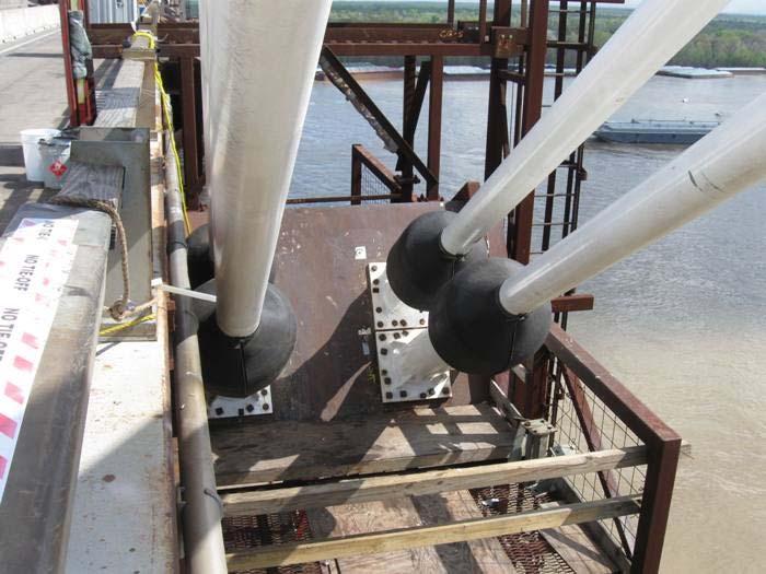
33 Lower Ends and Anchorages


34 Upper Ends and Anchorages

35 Maintenance of Traffic


36 Cable Vibration Suppression Measures


37 Cable Vibration Suppression Measures RIBBED HDPE PIPE WIND/RAIN ISSUES
38 Background: Deck Wearing Surface Original - (SMAC) Stone Matrix Asphalt Cement Observed failure and delaminations of significant areas (1994) (SMAC) Stone Matrix Asphalt Cement 1 st Rehab - Removed and replaced the area over 4 Travel Lanes Applied a test section utilizing Polymer Modified Asphalt Cement (PMAC) Observed failure and delaminations of significant areas 2 nd Rehab - Removed and replaced the area over 3 Travel Lanes utilizing PMAC Applied a 320 test section utilizing Conventionally Reinforced Concrete Pavement (CRCP) - Norhbound Barrier to Barrier Applied another 320 test section utilizing Steel Fiber Reinforced Concrete (SFRC) - Southbound 2 Lanes

39 Deck PMAC

40 Deck CRCP

41 SFRC
42

43


44

45


46


47


48
49 Project Team ( ) LA DOTD, PAUL FOSSIER, PROJECT MANAGER CABLE INSPECTION & REPLACEMENT CTL GROUP BRIDGE ENGINEERING SOLUTIONS (BES) TRANSYSTEMS ABMB INTERNATIONAL BRIDGE TECHNOLOGIES (IBT) KIEWIT, GENERAL CONTRACTOR VSL, INC., STAY CABLE SUB-CONTRACTOR DECK OVERLAY STRUCTURAL DESIGN & REHABILITATION (SDR) CEC, INC., GENERAL CONTRACTOR

50