ARCHITECTURAL ENGINEERING THE PENNSYLVANIA STATE UNIVERISITY THESIS PROJECT
|
|
|
- Juliana Fowler
- 5 years ago
- Views:
Transcription
1 ARCHITECTURAL ENGINEERING THE PENNSYLVANIA STATE UNIVERISITY THESIS PROJECT PASEO CARIBE CONDOMINIUM TOWER & PARKING Coupled Shear Wall Systems in High Seismic Zones PASEO CARIBE CONDOMINIUM TOWER & PARKING

2 ARCHITECTURAL ENGINEERING THE PENNSYLVANIA STATE UNIVERISITY THESIS PROJECT PASEO CARIBE CONDOMINIUM TOWER & PARKING
3 LOCATION San Juan, Puerto Rico Bordered by the Caribbean & South American Plates


4 LOCATION Caribbean Plate N. American Plate S. American Plate UBC 1997 Seismic Zone 3
5 Project Overview IV Phase Development Project
6 Project Overview Parking Garage: Phase II 10 stories, 1700 parking spaces
7 Project Overview Parking Garage: Phase II 10 stories, 1700 parking spaces Condominium Tower: Phase III Add. 14 stories 4 3,500 ft 2 aparts / floor
8
9 Gravity System Cast-in-Place Bearing Wall 9 Post-Tensioned Flat Slab Walls: 620 LF / Floor Typical Open Span: 17 E-W Lateral System Bearing Walls act as Shear Walls Very Stiff 10 x 160 Core 4 Elevator Shafts 3 Sets of Stairs


10 Lateral Discontinuity Transition of Occupancy at 8 th Floor Vertical Irregularity: UBC Table 16L Type 1: Soft Story Transfer Girders Type 2: Weight Mass Doubled Slab Area Type 3: Vertical Geometry > 1.3L Type 4: In plane Discontinuity
11 Lateral Discontinuity
12 Multiple Lateral Discontinuities Large Self Weight = 92,000k Low R Bearing Wall Value = 4.5 VERY LARGE SEISMIC FORCES V = 8400 KIPS
13 Non-Structural Issues In plan, no open space > 22 E-W Material and Labor Intensive Design Concrete: cy Formwork: 520,000 ft 2 Rebar: 560 tons
14 Efficient Lateral System: Reduce No. Lateral Elements to 4 in each direction Limit No. Irregularities Has a Predictable and Clean Failure Mechanism Does not interfere with the Architecture & Assigned Use of Space
15 KEY ELELEMENTS Reduce Vase Shear: Use a frame gravity system with a higher R: 5.5 Reduce the Weight with a lighter Steel Frame Improved Capacity: Higher f c = 5ksi Thicker 24 walls Diagonally Reinforced Coupled Walls Higher T to increase participation of coupled beam Limit discontinuity and use symmetry to keep a low ρ factor
16 Method Take advantage of the Existing 27 x30 Parking Grid
17 Method Take advantage of the Existing 27 x30 Parking Grid Requirements Existing Height w/ 9 P/T Slab: 230 ft UBC Overall Height Restriction: 240 ft Clear Story Height Required: 9 ft Max Story Height Increase: 8 in
18 Results Apartments Spacing: 7.5 Max Span: 27 Apartments: W10 x 26 Corridor: W14 x 30 H story = 5 H total = 70
19 Results Parking Garage CIRCULATION

20 Results Transition Level, 8th A6 15 W40x183 Girder
21 Results Connection Check Rn, kips Φ Lateral Flange Bending Local Web Yielding Local Web Crippling Web Buckling ΦRn, k Ru, kips
22 Proposed Layout COUPLED WALLS
23 COUPLED WALLS Proposed Layout Method Direct Shear ETABS Axial Dead & Live RAM Steel System W = 62,000 kips 25% Reduction Torsion Eccentric Loading Accidental Torsion, Ax = 2 Load Combinations ρ = 1.1 C a = D + 1.2E (Load Case 1) 1.48D + 1.2E L (Load Case 2)


24 ETABS MODEL COUPLED WALLS

25 Summary Results COUPLED WALLS

26 Coupled Beams CR Ratio = 27% Results Details Vertical: #4@6 Horizontal: #6@9 Diagonal Ties: #4@4 COUPLED WALLS
27 Coupled Beams CR Ratio = 27% Results Details Vertical: #4@6 Horizontal: #6@9 Diagonal Ties: #4@4 COUPLED WALLS
28 Flexure ФMn 1 st Level L = 33 ft B.Z: 39 #11 Web: #10@9 ФMn = ft-k > ft-k COUPLED WALLS

29 COUPLED WALLS
30 COUPLED WALLS
31 COUPLED WALLS Flexure, ФMn Story Height, ft Cut-Off Requirements 0.8*L Vertical Reinforcement Flexural Demand vs. Height Coupled Walls = 12.8 ft 1210 ft - kips = 12.8ft 2400 ft - kips 4290 ft - kips Mu, ft-kips Moment Demand 12th Story Mn REQ 16th Story Mn REQ 19th Story Mn REQ
32 Flexure, ФMn Cut-Off Requirements 0.8*L Vertical Reinforcement = 12.8 ft COUPLED WALLS
33 COUPLED WALLS Ductility & Plastic Hinge Development Preferred Plastic Hinge at Base: Minimize Impact on Non- Structural Systems Θ 1 < θ 9 θ 9 θ 1

34 Ductility & Plastic Hinge Development Virtual Work COUPLED WALLS
* V u v pr u u COUPLED")
35 Minimum Shear and Magnified Shear Demand V * = ϖ ( M / M )* V u v pr u u COUPLED WALLS
 0.1P = l 0.")
36 COUPLED WALLS Boundary Zones Requirements Length P u < 0.10A g f ' c M u < 1.0 luvu M u V u < 3A f ' c, < 3 cv l V B. Z( ft) 0.1P = l 0.2P w u o u u Ties: #5@6
37 Final Design COUPLED WALLS

38 Final Design COUPLED WALLS
39 Final Design COUPLED WALLS
40 Architecture Saved 160 ft 2 / Floor Flexible and Open Plan for: Architect Owner Future Tenants Larger Open Areas of up to 50
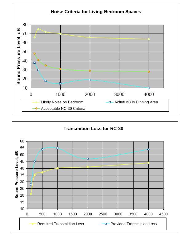
41 Acoustics
42 Acoustics Vibrations Living Areas: W10X15 TO W10X26
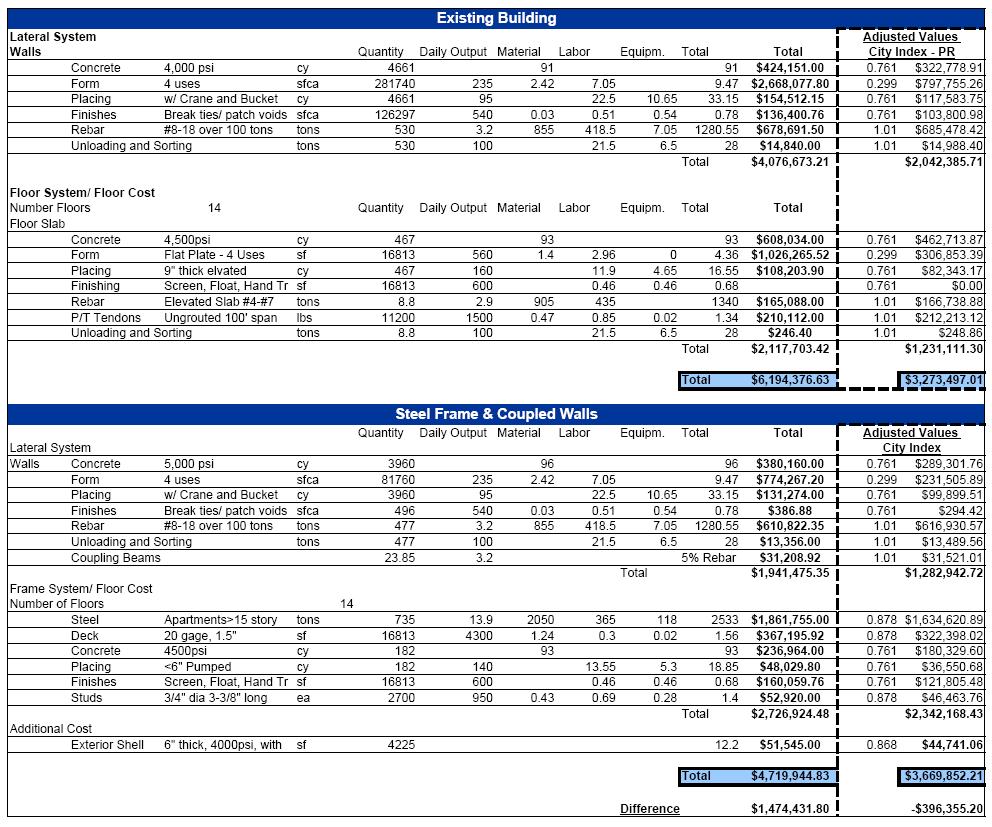
43 U.S Cost $1,000,000 Savings Formwork 450,000 sfca Rebar Placement 100 tons Puerto Rico $400,000 Deficit Concrete Labor Market 12% Finishes & Partitions 323%
44
45 Current design reflects the labor practices and situation of the country Designers applied the best and most economical design to a complicated structure Coupled wall systems proved to be an effective resisting system, allowed for increased floor area and architectural freedom Reduced the amount of material and labor required for the project Overall: Good design when the resources are available
46 THANK YOU