STRUCTURAL INSPECTION SANCTUARY/ OFFICE BUILDING Memorial Drive Houston, Texas 77079
|
|
|
- Rosemary Shaw
- 5 years ago
- Views:
Transcription
 491-1262 WWW.CRITERIUM-FARRELLYANCY.")
1 STRUCTURAL INSPECTION SANCTUARY/ OFFICE BUILDING Memorial Drive Houston, Texas Prepared for: Emanuel Episcopal Church c/o Ms. Alice Busch Prepared by: Criterium Farrell Yancy Engineers Texas Registered Engineering Firm F Bluebonnet Drive, Suite 115 Stafford, Texas (281) Bill Hicks, P.E. David L. Yancy II, P.E. Inspection No N Date of Inspection: October 17, 2017 & October 18, 2017 The seal appearing on this document was authorized by David L. Yancy II, P.E and Bill Hicks, P.E on November 27, 2017 for distribution.
2 TABLE OF CONTENTS INTRODUCTION... 1 LIMITATIONS... 1 DEFINITIONS... 3 DESCRIPTION... 4 FLOOD DATA... 4 SITE... 5 FOUNDATION... 5 FRAMING... 7 EXTERIOR... 9 INTERIOR CONCLUSION ATTACHMENTS: 1 Site Location and Aerial Map Overview 2 Precipitation Map 3 Precipitation Data 4 Addicks Reservoir Information 5 Buffalo bayou Reservoir Information 6 FEMA Flood Insurance Rate Map (FIRM) 7 Building Sketches PHOTOGRAPHS
3 INTRODUCTION From August th 2017, the Greater Houston Metropolitan Area and other parts of southern Texas were impacted by Hurricane Harvey, a historic weather event which caused high winds, tornadoes and extreme flooding throughout the region. It is our understanding that the church has experienced some flood damage to the buildings on the property from Hurricane Harvey and have asked us to evaluate these buildings. The purpose of this inspection and report is to evaluate the extent of any structural damage caused by the flood and to determine what, if any, significant maintenance, repairs, and/or replacement might be expected within the next few years. This inspection was performed by and report written by Bill Hicks, P.E. and David L. Yancy II, P.E. The report that follows has been prepared from the perspective of what an owner of this property would benefit from knowing. Thus, it discusses many things beyond those that are of immediate concern. Therefore, the report needs to be read in its entirety to understand fully all the information that has been obtained. This written report is the complete response to your request for an inspection of this property and should be read in full. Any verbal statements made during the inspection are made as a courtesy only and are not considered a part of this report. If you have any questions about this report or our inspection, please call our office immediately for clarification. If there is any area of this property where you have a particular concern based either on this report or your own personal observations, we recommend a more exhaustive technical evaluation. LIMITATIONS This report is based on an examination of the structural systems in this building. This report is an opinion about the condition of this building. It is based on visual evidence available during a diligent inspection of all reasonably accessible areas of the surrounding property, building exterior, interior and foundation. No surface materials were removed, no destructive testing undertaken, or furnishings moved. It is not the intent of our inspection to detail every minor defect we might find. We do, of course, look for problems, particularly those we would consider major deficiencies. Please keep in mind that we generally define a major deficiency as one that would cost approximately $ or more to correct. Our inspection and report do not include code compliance, mold investigations, environmental investigations, indoor air quality analysis, municipal regulatory compliance, subsurface investigation, or records research related to the property pertaining to past use or flood history of the property. Page 1
4 Indoor air quality is a growing concern. Mold and mildew, fostered by moisture accumulation due to flood waters, can lead to respiratory discomfort and aggravate allergies and other respiratory conditions. Inspecting for mold is not included in the scope of a structural inspection. Such an investigation, if desired, should be undertaken by individuals specifically trained and qualified for such work. As Professional Engineers, it is our responsibility to evaluate available evidence relevant to the structural systems in this building. We are not, however, responsible for conditions that could not be seen or were not within the scope of our service at the time of the inspection. This inspection and report have been conducted in compliance with the standards of practice of Criterium Farrell Yancy Engineers and in a manner consistent with that level of care and skill that is ordinarily exercised by members of the profession practicing under similar conditions at the time the services are performed. Our report is based on an examination of the major structural systems in this building; specifically the foundation, the framing, the property drainage, and any structural columns and/or posts. We look at the exterior veneer, exterior siding, interior walls, trim, windows, doors or frames only to see if any signs of structural damage are present and not to render an opinion of the condition of these items. Issues concerning the veneer, siding, trim, windows, doors or frames, or any associated rot, caulking, etc., are not included in the scope of a structural inspection of this nature and, if we address any of these items in our report, it is only as a courtesy and should not be considered an opinion of these items or all-inclusive list of deficiencies. Such weather as flooding and hurricanes can cause damage to other systems of the building including but not limited to the roof, electrical, gas line, sewage, chimney, heating and air conditioning, in addition to cosmetic, and other damage to the buildings that is not visible or apparent during an inspection which does not undertake destructive or exploratory actions. Please note that these items are typically addressed by an insurance claims adjuster or a licensed contractor and will not be considered in this report. Statements made in this report should not be considered a design solution. Comments regarding repair are provided in an attempt to quantify the visible magnitude of work. Responsible parties should consult the appropriate design professional(s) and contractors to prepare repair plans or obtain quotes for work. Licensed professionals should only perform repairs of any deficiencies or concerns noted in the report. Please note that we may emphasize some comments using bold type to highlight deficiencies that require attention. This emphasis is intended to call your attention to certain observations we believe are important to your consideration of this building. However, you should not assume that these are the only observations that may be important to you. Please be sure to read our report thoroughly and completely. Page 2
5 DEFINITIONS For your reference while reading our report, the following definitions may be helpful: Average - Excellent - Good - Component or system compares to what is typical for construction in the geographic area in which the inspection occurs. It also compares it to buildings of similar age and construction type. Since construction practices vary from region to region, average is intended to be region specific. Component or system is in as new condition, requiring no rehabilitation, and should perform as expected. Component or system is sound and performing its function, although it may show signs of normal wear and tear. Some normal maintenance work may be required. Fair - Component or system falls into one or more of the following categories: a) Evidence of previous repairs not in compliance with commonly accepted standards, b) Workmanship not in compliance with commonly accepted standards, c) Component or system is obsolete, d) Component or system approaching end of expected performance. Repair or replacement is required to prevent further deterioration or to prolong expected life. Poor - Minor distress - Component or system has either failed, or cannot be relied upon to continue performing its original function as a result of having exceeded its expected performance, excessive deferred maintenance, or state of disrepair. Present condition could contribute or cause the deterioration of other adjoining elements or systems. Repair or replacement is required. Slab cracks less than 1/16-inch in width and not numerous Masonry- cracks less than 1/8-inch wide and not numerous. Few or no separations at joints, windows, doors, and differing materials greater than ¼-inch Interior cracks less than 1/16-inch in width and infrequently encountered Moderate distress - Slab cracks greater than 1/16-inch and less than 1/8-inch in width Masonry intermittent cracks less than ¼-inch in width and separations at joints in the ¼-inch to ½-inch range Interior - numerous signs of settlement including drywall cracks up to 1/8-inch Severe distress - Slab cracks greater than 1/8-inch Masonry cracks greater than ¼-inch in width or separations at joints exceeding ½-inch Interior cracks greater than 1/8-inch in width. Typically numerous All ratings are determined by comparison to other buildings of similar age and construction type. Page 3
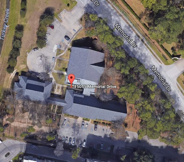
6 DESCRIPTION The Emmanuel Episcopal Church is generally located at the southeast corner of Memorial Drive and Eldridge Parkway (Attachment 1). The campus consists of three buildings which are as follows: 1. Sanctuary and Office Building 2. Russell Hall (connected to the Sanctuary via an enclosed breezeway) 3. Education Building with playground This report covers the Sanctuary and Office Building only. Please refer to the additional reports issued discussing the other two buildings. The property is generally located in west Harris County adjacent to Turkey Creek, which drains into Buffalo Bayou, approximately 2,200 feet northeast of Buffalo Bayou and about 1.7 miles due east of Barker Reservoir. For purposes of this report, all directions (left, right, rear, etc.) are taken from the viewpoint of an observer standing in front of the building and facing it; or, when discussing a specific item, from the viewpoint of standing in front of that component (doorframe, window, etc.). FLOOD DATA Data from the Harris County Flood Warning System shows that over 35 inches of rain was recorded near the property (Attachments 2 & 3). The nearest stream elevation sensor (sensor ID located at Dairy Ashford and Buffalo Bayou) captured the high mark of Buffalo Bayou at 76.9 feet at this location. In addition, the local drainage channels (Buffalo Bayou and Turkey Creek) were outside their banks for over 12 days (Attachments 4 & 5). It is our understanding that the buildings onsite were flooded for about 10 days, which is consistent with the data from the Harris County Flood Warning System. The Flood Insurance Rate Map (FIRM) for this area (Map 48201C0640L) identifies the 1% annual chance (100-year) flood as an elevation of 72 feet (Attachment 6). Based on the information available, at the nearest stream sensor, the high flood level was about 4.9 feet above the 1% flood. Taking this data back to the location of the subject property, which has a 1% flood level of about 76 feet would indicate that the high point of the flood would have been about 81 feet elevation. According to Google Earth, the elevation of the property varies from 78 to 80 feet. So according to the data, the high flood level was anywhere from one to three feet above grade. This is very consistent with the Photographs taken of the high-water marks (Photograph 7) which shows the mark for the Sanctuary at 29 inches. Page 4
7 SITE In many areas of southeast Texas, soils have high contents of expansive clays that swell when wet and shrink when dry 1. Building foundation and structural damage can result from the shrink-swell pressure exerted by the soil. More or less uniform moisture levels can help preclude cyclic expansion and contraction of the soil with its resulting foundation movement. Topography of the property is generally flat (according to Google Earth, the site elevation varies from 78 to 80 feet above mean sea level) with drainage generally from the east of the property to Turkey Creek which is located to the west of the property (see Attachment 1). Ground slope adjacent to the foundation around the perimeter was less than desirable and no underground drainage was noted. All low spots where excess water can accumulate should be filled and sloped so water drains naturally away from the foundation. We mention this because poor drainage is a frequent contributor to differential movement. We did not observe any areas of erosion or scour in close proximity to the building due to moving flood waters. The soil against the slab generally appeared to be firm and stable. Trees were observed within 10 feet of the foundation. Trees can contribute to differential movement in a foundation because the roots of trees consume large quantities of moisture from the soil, causing the soil to dry and shrink much faster than other areas. Some studies indicate that trees should not be closer than the mature height of the tree to the foundation. We normally do not recommend removal of mature trees (unless observations indicate obvious foundation damage) because the decaying roots may have a more detrimental effect. FOUNDATION The following areas were inaccessible or not visible, and this limited the extent of our structural inspection: Most of the foundation system and slab (underground) The edge of the slab in some areas Based on our experience with similar construction, this building likely has a concrete slab foundation founded on drilled piers. Since the piers would be under the slab, we have no way of observing this during an inspection that is visual and non-destructive in nature. The type and amount of steel reinforcing in the slab cannot be determined by a visual inspection. However, it is most likely conventionally reinforced with steel reinforcing bar spaced uniformly throughout the slab. Grade beams under load bearing portions of the building provide the foundation. Drilled piers are located at strategic points under the grade beams and extend an unknown depth into the soil. These piers provide a generally stable base for the foundation. The grade beams are deeper than the 1 United States Department of Agriculture Soil Conservation Service, Soil Survey of Harris County, 1967 Page 5
8 rest of the slab and they contain additional steel reinforcing. The roof framing is supported by interior and exterior bearing walls and beams. This is a standard method of construction for buildings such as this. At the time of this inspection, we had not been informed of any prior foundation repairs. If there have been any repairs to the foundation, we were not a party to any repair design or the repair process. We performed a survey of the floor elevations in the building using a Technidea Zip Level 2000, which the manufacturer states is reliably accurate to within 1/8 th of an inch over a vertical range of plus or minus twenty feet. We measure from a zero elevation located near the center of the building. The zero elevation line is not intended to indicate original floor elevation, but is used as a reference point for the other elevations. The majority of measurements obtained were around the perimeter of the building. Adjustments were made to accommodate for steps, changes in floor coverings, and other built-in variances. We noted slight elevation variance throughout much of the building with a maximum change of about 1.1 inches in 15 feet (a slope of 0.6%), measured from the main entry on the south side to the main hallway in the office area at the south side of the Vestibule. In general, slopes of less than 1 inch in 10 feet are consistent with satisfactory foundation performance in this region. The maximum measured differential is well within that parameter. The high point was at the main entry on the south side of the building (Elev. 0.7) and the low point was at the northwest of the Mechanical Room (Elev. -1.1). The total deviation across the foundation was 1.8 inches. Typical construction tolerances can provide for up to 1.5 inches of total deviation across a new foundation. The total deviation of this foundation is just above the tolerance for a new foundation and is within typical expectations for performance for older foundations. Overall, the measured differentials within the floor plan are also well within standards for satisfactory foundation performance in the region. A review of the level survey indicates that with the exception of the Mechanical Room, the foundation is very level in the Nave. West of the Nave, the readings become less consistent and there is a defined slope with lower areas toward the northwest. This slope could be the result of numerous items, one of which could be a difference in pier size or depth in the office area. While we believe that piers were installed under the perimeter grade beams and arches, we are not certain as to the dimensions and depths of these piers if they are all consistent. We statistically modeled our data on a level distortion heat map to illustrate the current foundation slope and any localized deflection. Contours are plotted at 1/2 inch intervals to minimize the impact of small relative elevation differences related to variations in construction or flooring installation. In reviewing the level readings for the Sanctuary building in coordination with Russell Hall it was noted that the lower areas of the Sanctuary were in the vicinity of Russell Hall. This data could be purely coincidental or it could point to differential settlement in the area where these two buildings are close to each other. Page 6
9 According to Principal Faults in the Houston, Texas, Metropolitan Area (2005 by Shah and Lanning-Rush, Scientific Investigations Map 2874) the only fault close by is the Long Point Fault which is about one mile to the southeast of the subject properties. We do not believe that this fault is active or resulting in any settlement of these buildings. Another possible scenario is that construction of Russell Hall caused slight settlement in the soil around the northwest of the Office. Other factors could also have resulted in this settlement. As this inspection is a snap-shot in time, it is not possible to state whether or not movement in the foundation will continue. This can only be determined by observation of the foundation over time. A monitoring program should be established to monitor the position of the foundation system over time to be sure that movement, if any, is minor. We recommend having these level surveys performed again within the next few years to see if there is further settlement or if the readings remain consistent. If significant movement is observed, remedial action will be required. Regardless, the total deviation and slopes at the time of inspection are within expected boundaries. We noted several areas on the foundation which contained slab cracks (in the Chancel, the Nave, and in the office area Photograph 37). The cracks were generally hairline in width and of varying lengths. You should note that many foundations develop cracks. At the time of inspection, the degree of cracking in this building does not indicate structural instability. It is possible that some additional cracking of the concrete slab exists in areas concealed from view. Based on visible evidence and measured differentials, we consider the foundation to be structurally sound with no recommendation for repairs. With normal care, and attention to maintenance of stable moisture content in the soil surrounding the foundation, the slab should continue to be structurally sound for the foreseeable future. Although no damage was observed at the time of the inspection, soil conditions in this area are known to be unstable. Please note, no warranty against future movement can be made. FRAMING Our evaluation of this structure is based on many indirect observations. We cannot see most of the framing that is concealed behind drywall or ceilings. We look for cracks, bulges, and other evidence of distress or deterioration to help us evaluate the condition. As with any limited inspection, it is possible that there are structural deficiencies that cannot be known. The following areas were inaccessible or not visible, and this limited the extent of our structural inspection: Portions of the attic area Portions of the wall framing (concealed by drywall) Page 7
10 The exterior walls of this building are standard wood-frame construction. Wall framing generally consists of dimensional lumber (sill plates, wall studs, and top plates). The attic framing is primarily dimensional lumber used as ceiling joists, rafters and purlins. The roof framing in the Nave, Chancel, and Vestibule (east of the main entry) is engineered glue laminated timber (glulam) arches (Photographs 10 and 11). The roof framing in the rest of the building is supported by interior and exterior bearing walls and beams. These are standard methods of construction for buildings such as this. We saw no visible evidence of any significant rot present in the framing of this structure that was visible at the time of inspection. However, you should not assume that no rot exists in any of the inaccessible areas. Rot can result from moisture accumulating underneath the siding, behind trim, or within the wall cavities should the normal drying process be restricted by insulation or other obstacles. It is possible that you will encounter some rot should you at any time undertake any projects that involve disassembly of the portions of this structure normally inaccessible to visual inspection. The primary roof support in the Sanctuary consists of the wood glulam arches. Like any other wood products, these elements change as the ambient humidity and moisture changes. As a result, small surface fractures called checks can appear as the wood swells and shrinks due to the humidity and moisture changes. If the fracture occurs across the full width (bottom face not to be confused with the depth or thickness of the arch) of the arch it is called a split. These splits normally occur at the end of the glulam. Checks of varying width and depth were noted in the arches (Photographs 27 and 28). While these are considered structural defects, they are common in glulam arches as they age. We noted checks which were located below the flood level and some which were located above the flood level. Some of these checks identified are considered normal wear and tear and some are specific to the moisture received during the flood and the subsequent drying out period. We did not find any splits in the arches. The APA Engineered Wood Association produces Form No. EWS R475E in which it explains the criticality of certain check and split defects in glulam timbers. In this document it is noted that in compression members (such as the lower portion of the arches, acting as columns, which are in the Sanctuary) checks are not structurally significant unless they become splits. One arch exhibited signs of delamination (Photograph 29). These are usually more rare than checks as the glue line is usually stronger than the tensile strength of the wood fibers, these are treated the same as checks in that until they penetrate across the bottom face (width) of the member, the compressive strength is not changed. The depth of the delamination noted is not considered significant and there was no matching delamination on the opposite side of the arch. As we did not identify any splits, all the checks and the single delamination in the arches are not structurally significant and the load bearing capacity of the arches are not compromised. This arch observation only covers the lower part of the arches (eye level and below) and does not cover any portion of the upper part of the arches which have shear as well as compressive forces at work. We noted some corrosion of anchor bolts at the arch base plates (Photograph 26). In order to keep the attachment secure in the future, we recommend replacing all anchor bolts and nuts with new material. The base plates appeared in satisfactory condition and no replacement or repairs to them are recommended. Page 8
11 With a two-pin moisture meter (General Model MMD4E) which the manufacturer warrants as accurate to within ± 2% we took moisture readings of the glulam arches. Most of the arches were below the 15% recommended threshold for moisture in framing members; however, a few were above that amount (Photographs 23, 24, and 25). A floor plan with the moisture readings captured is in Attachment 7 (Sketches). We recommend waiting until these arches show moisture levels below 15% before placing drywall or insulation around them. Moisture readings were also taken at the soleplates around the Sanctuary and Office areas and all were less than 15%. Although not visible, no significant deflection of the walls or ceiling joists was observed and they appeared to be firm and generally level. We observed no apparent cracks, separations or misaligned framing members that would indicate structural instability due to flood damage. Based on areas accessed, no major structural problems were observed in the visible framing members. We did identify some framing members which were tilted and should be re-plumbed. These were at the entry to the Narthex (Photographs 20, 21, and 22) and the wall between the Lounge and the Meeting Room in the Office area (Photograph 34). Additionally, some damage likely occurred while the sheetrock was being removed and some repairs to wall studs and framing will be needed such as seen in Photographs 32 and 35). We noted flood damaged sheathing and/or weather resistant barrier between the exterior vertical wood siding and the wall studs in multiple locations throughout the building (such as in Photographs 17, 19, 36, and 38). This sheathing serves as lateral stability for the wall framing as well as a substrate to secure the weather resistant barrier. You should be aware that currently adopted residential codes require sheathing and a weather resistant barrier in the complete wall assembly. Therefore, you should anticipate deconstruction of the exterior veneer to remove the remaining portions of damaged sheathing and replace it with new sheathing and a weather barrier. EXTERIOR The visible exterior vertical wood siding is a veneer that has been installed over the wood framing. These walls and the veneer appear to be in good condition. We were able to observe a visible high water mark on the exterior siding. We measured a high-water mark of approximately 29-inches on the south side of the building near the main entry (Photograph 7). This siding is dense and tough, but is quite vulnerable to moisture penetration and deterioration. This siding should be kept well maintained and, in particular, all joints and edges should be kept well caulked to minimize moisture penetration. Page 9
12 Several Exterior items need to be addressed: Some preliminary indications of rot (peeling paint, delamination, or swelling) or conditions that sustain wood destroying fungus were noted. In particular, these early signs were visible on the doors at the southeast and the north side (Photographs 8 and 9). Several of the windows in the Nave had openings around the jambs (Photographs 13 and 14). These apparently are not original windows and when they were installed, flashing at the jambs and likely the header and sill was not installed. This flashing is necessary in order to help keep moisture out of the building and off the framing members. The inside corner at the Meeting Room was not sealed properly and was open to the outside (Photograph 33). This joint should be sealed to help prevent moisture intrusion in the building. Also at this inside corner, moisture damage was visible to the sheathing (Photograph 33). This should be investigated further during the overall building repairs and appropriate sealing performed to keep out moisture. There was an opening visible at the southeast corner of the building (just south of the Chancel Photograph 18). This needs to be covered appropriately as it currently is an avenue for moisture intrusion. There was a broken window in the office just west of the main entry. We believe that while you have the siding removed, in order to replace the sheathing, that the windows should receive new flashing, the inside corner joint be sealed, and the area below the siding be closed off in order to help keep moisture from entering into the wall cavity and building envelope. The walkways are concrete slab-on-grade that are in average condition. As these are concrete slabs approximately four inches in depth with limited reinforcement, they are subject to movement and cracking from flooding. There was no apparent damage to the flatwork as a result of the flooding. We noted minor cracking in some of the concrete flatwork (such as in Photograph 8). If the cracks become greater than ½ inch in width or have elevation difference across them (greater than ¼ inch), you may want to consider repair so they do not become safety hazards. INTERIOR In this section of the report, we are concerned with those things that are technically and financially significant. For example, stains which might indicate roof or plumbing leaks, older wall or ceiling material which may require repair/replacement; the use of substandard materials on interior walls or ceilings; or the quality and condition of such items as the doors, windows, and cabinetry are those things which can affect the overall quality and condition of a building. The height of the high-water mark noted previously indicates that interior finishes in the building experienced contact with flood water up to a minimum of three feet. Page 10
13 Generally, the interior walls of this building and ceilings of this building are finished with drywall and paint. Drywall on the ground floor has been removed due to contact with flood water to facilitate the drying process. Much of the flooring has been removed due to flood damage and contact with flood water. As such, there were no significant findings regarding the interior finishes. CONCLUSION In summary, the building has experienced only cosmetic damage caused by the flooding from Hurricane Harvey. The normal signs associated with problematic structural movement and failure due to flood damage (i.e. large drywall cracks in the upper levels, framing that is mis-aligned, bowing walls, many sticking doors, etc.) are not apparent. The damage noted appears to be the direct result of contact with brackish flood water and not any significant hydraulic forces against the building. It is our opinion that the structural systems in this building are performing as intended and the building is structurally sound. Repair of cosmetic items should be performed by qualified professionals. Please note, with the exception of topographic modeling, rotation measurements and moisture readings, we did not perform any computations or other engineering analysis as part of this evaluation. In addition, our report is our opinion of the conditions observed on the days of our inspection and we reserve the right to add or modify our opinions if additional information should become available. There is no single way to build, renovate or remodel a building. As a result, you may encounter contractors whose opinions about the condition of this building will differ from ours. We cannot be responsible for any action you may take based on those opinions unless we have the opportunity to review the situation and examine the relevant conditions before any repairs and/or modifications are made. This report has been prepared for your benefit and in strict confidence with you as our client. No reproduction or re-use of this report for the benefit of others is permitted without expressed written consent, except as may be required by Texas real estate regulation. Further, except as required by regulation, we will not release this report to anyone without your permission. As noted, the inspection represented by this report focuses on the major structural systems in this building. If you have any questions about this report or inspection, please feel free to call our engineer for clarification. There is no additional charge for a reasonable number of phone consultations. Should an additional visit to the building be necessary, however, an additional fee will be charged. Thank you for the opportunity to be of assistance to you. Page 11


14

15
16
17
18

19
20 Damaged Emmanuel Episcopal Church - Sanctuary Criterium- Farrell Yancy Engineers Memorial Dr, Houston, TX, United States (281) Attachment 7 1st Floor Moisture Readings MEETING ROOM WOMEN S Damaged cripple stud MECHANICAL TOILET LOUNGE MEN S VESTIBULE HALL king stud SANCTUARY NARTHEX OTHER OFFICE Broken window STORAGE Flashing Flashing Flashing needed at needed needed HALL MAINTENANCE 17 THIS FLOORPLAN IS FOR ILLUSTRATIVE PURPOSES ONLY AND PROVIDED WITHOUT WARRANTY OF ANY KIND INCLUDING SATISFACTORY QUALITY OR ACCURACY OF DIMENSIONS. MEASUREMENTS AND ASPECTS ARE APPROXIMATIONS AND MAY NOT BE TO SCALE. 0' 16' 32' 48' 1:291 1
21 Emmanuel Episcopal Church - Sanctuary Criterium- Farrell Yancy Engineers Memorial Dr, Houston, TX, United States (281) Humidity / Temp. Measure - Date #1: Surf.Humidity #1: 12.8% 7 Humidity / Temp. Measure - Date #1: Surf.Humidity #1: 13.5% 8 Humidity / Temp. Measure - Date #1: Surf.Humidity #1: 13.2% 1 Humidity / Temp. Measure - Date #1: Surf.Humidity #1: 13.5% 2 Humidity / Temp. Measure - Date #1: Surf.Humidity #1: 16.9% 3 Humidity / Temp. Measure - Date #1: Surf.Humidity #1: 14.4% 4 Humidity / Temp. Measure - Date #1: Surf.Humidity #1: 16.6% 5 Humidity / Temp. Measure - Date #1: Surf.Humidity #1: 14.4% 6 Humidity / Temp. Measure - Date #1: Surf.Humidity #1: 11.2% 13 Humidity / Temp. Measure - Date #1: Surf.Humidity #1: 12.4% 14 Humidity / Temp. Measure - Date #1: Surf.Humidity #1: 15.5% THIS FLOORPLAN IS FOR ILLUSTRATIVE PURPOSES ONLY AND PROVIDED WITHOUT WARRANTY OF ANY KIND INCLUDING SATISFACTORY QUALITY OR ACCURACY OF DIMENSIONS. MEASUREMENTS AND ASPECTS ARE APPROXIMATIONS AND MAY NOT BE TO SCALE. 2
22 Emmanuel Episcopal Church - Sanctuary Criterium- Farrell Yancy Engineers Memorial Dr, Houston, TX, United States (281) Humidity / Temp. Measure - Date #1: Surf.Humidity #1: 18.6% 16 Humidity / Temp. Measure - Date #1: Surf.Humidity #1: 14.4% 12 Humidity / Temp. Measure - Date #1: Surf.Humidity #1: 14.6% 9 Humidity / Temp. Measure - Date #1: Surf.Humidity #1: 11.6% 10 Humidity / Temp. Measure - Date #1: Surf.Humidity #1: 15.5% 11 Humidity / Temp. Measure - Date #1: Surf.Humidity #1: 12.5% THIS FLOORPLAN IS FOR ILLUSTRATIVE PURPOSES ONLY AND PROVIDED WITHOUT WARRANTY OF ANY KIND INCLUDING SATISFACTORY QUALITY OR ACCURACY OF DIMENSIONS. MEASUREMENTS AND ASPECTS ARE APPROXIMATIONS AND MAY NOT BE TO SCALE. 3
23 Emmanuel Episcopal Church - Sanctuary Criterium- Farrell Yancy Engineers Memorial Dr, Houston, TX, United States (281) st Floor MEETING ROOM -0.5 WOMEN S TOILET MECHANICAL LOUNGE MEN S VESTIBULE HALL SANCTUARY NARTHEX -0.3 OTHER OFFICE STORAGE HALL 15.2 MAINTENANCE THIS FLOORPLAN IS FOR ILLUSTRATIVE PURPOSES ONLY AND PROVIDED WITHOUT WARRANTY OF ANY KIND INCLUDING SATISFACTORY QUALITY OR ACCURACY OF DIMENSIONS. MEASUREMENTS AND ASPECTS ARE APPROXIMATIONS AND MAY NOT BE TO SCALE. 0' 16' 32' 48' 1:291 4

24 Not to Scale ATTACHMENT 7 FOUNDATION CONTOUR MAP EMANUEL EPISCOPAL - SANCTUARY MEMORIAL DRIVE HOUSTON, TEXAS 77079
25 0' 4' 8' 12' 16' 20' 1:128 (3/32" = 1') THIS FLOORPLAN IS FOR ILLUSTRATIVE PURPOSES ONLY AND PROVIDED WITHOUT WARRANTY OF ANY KIND INCLUDING SATISFACTORY QUALITY OR ACCURACY OF DIMENSIONS. MEASUREMENTS AND ASPECTS ARE APPROXIMATIONS AND MAY NOT BE TO SCALE. Attachment 7 1st Floor Elevation Survey - Sanctuary MEETING ROOM MECHANICAL WOMEN S TOILET CONFERENCE ROOM LOUNGE MEN S VESTIBULE -0.6 HALL SANCTUARY STORAGE NARTHEX -0.3 PRIVATE OFFICE 0.0 OTHER 0.3 OFFICE STORAGE HALL 15.2 MAINTENANCE


26 Location: Photo Taken by: Date: Memorial Drive Bill Hicks, P.E. October 17-18, 2017 Houston, Texas East side of Sanctuary 1 South side of Sanctuary/Office 2


27 Location: Photo Taken by: Date: Memorial Drive Bill Hicks, P.E. October 17-18, 2017 Houston, Texas Northeast corner of Sanctuary 3 North side of Sanctuary 4


28 Location: Memorial Drive Houston, Texas Photo Taken by: Bill Hicks, P.E. Date: October 17-18, 2017 Southwest corner of Office 5 South side of Sanctuary/Office 6


29 Location: Photo Taken by: Date: Memorial Drive Bill Hicks, P.E. October 17-18, 2017 Houston, Texas Water line at entry 29 inches 7 Damage to door at south side east 8


30 Location: Photo Taken by: Date: Memorial Drive Bill Hicks, P.E. October 17-18, 2017 Houston, Texas Damage to door at north side 9 View inside Sanctuary of Nave and Chancel 10


31 Location: Photo Taken by: Date: Memorial Drive Bill Hicks, P.E. October 17-18, 2017 Houston, Texas Roof support in Sanctuary engineered laminated arches with king post and tie beam 11 Typical window framing in Sanctuary 12


32 Location: Photo Taken by: Date: Memorial Drive Bill Hicks, P.E. October 17-18, 2017 Houston, Texas Flashing needed at window jamb in Sanctuary 13 Flashing needed at window jamb in Sanctuary 14


33 Location: Photo Taken by: Date: Memorial Drive Bill Hicks, P.E. October 17-18, 2017 Houston, Texas Framing at southeast of the Chancel 15 Framing at northeast of Chancel and Mechanical Room 16


34 Location: Photo Taken by: Date: Memorial Drive Bill Hicks, P.E. October 17-18, 2017 Houston, Texas Warped plywood sheathing at southeast of Sanctuary 17 Outside light visible southeast of Chancel 18


35 Location: Photo Taken by: Date: Memorial Drive Bill Hicks, P.E. October 17-18, 2017 Houston, Texas Gypsum sheathing damage at Chancel east side 19 Stud displacement at the sill plate at entry to Narthex 20


36 Location: Photo Taken by: Date: Memorial Drive Bill Hicks, P.E. October 17-18, 2017 Houston, Texas Close-up of stud displacement 21 Stud tilt at framed opening to Narthex 2.4 degrees 22


37 Location: Photo Taken by: Date: Memorial Drive Bill Hicks, P.E. October 17-18, 2017 Houston, Texas Moisture content in engineered laminated arch 16.6% 23 Moisture content in engineered laminated arch 16.9% 24


38 Location: Photo Taken by: Date: Memorial Drive Bill Hicks, P.E. October 17-18, 2017 Houston, Texas Moisture content in engineered laminated arch 18.4% 25 Typical corrosion at arch anchor bolts 26

 of arch 3/32 inch 27 Checking of side face")
39 Location: Photo Taken by: Date: Memorial Drive Bill Hicks, P.E. October 17-18, 2017 Houston, Texas Checking of bottom face (width) of arch 3/32 inch 27 Checking of side face (depth) of arch slightly less than 1/16 inch 28

 of arch slightly less than 1/16 inch 29")
40 Location: Photo Taken by: Date: Memorial Drive Bill Hicks, P.E. October 17-18, 2017 Houston, Texas Slight delamination in side face (depth) of arch slightly less than 1/16 inch 29 Typical framing in office area (northwest corner shown) 30


41 Location: Photo Taken by: Date: Memorial Drive Bill Hicks, P.E. October 17-18, 2017 Houston, Texas Typical framing under windows in office area on south side 31 Dislocated stud in hallway near the Parish Hall 32


42 Location: Photo Taken by: Date: Memorial Drive Bill Hicks, P.E. October 17-18, 2017 Houston, Texas Daylight visible at the inside corner joint at the Meeting Room and signs of moisture damage to sheathing 33 Tilted wall stud between Meeting Room and Lounge 34


43 Location: Photo Taken by: Date: Memorial Drive Bill Hicks, P.E. October 17-18, 2017 Houston, Texas Cased opening jamb not braced securely and cripple stud is dislodged 35 Warped plywood sheathing at west wall of office area 36


44 Location: Photo Taken by: Date: Memorial Drive Bill Hicks, P.E. October 17-18, 2017 Houston, Texas Slab crack in Loounge 37 Damaged gypsum sheathing in office southwest area 38