Handley McDonald. Handley McDonald. Technical Report 1. Claude Moore Medical Education Building Faculty Advisor: Richard Behr
|
|
|
- Kathlyn Powell
- 5 years ago
- Views:
Transcription


1 Handley McDonald Technical Report 1 Faculty Advisor: Richard Behr
2 TABLE OF CONTENTS Executive Summary 3 Building Information.4 Structural System Overview.6 Foundation 6 Floor System.7 Framing System..8 Lateral Resisting System..8 Design Codes 10 Materials Used...11 Gravity Loads 12 Dead and Live Loads.12 Snow Loads.13 Lateral Loads.13 Wind Loads.14 Seismic Forces..18 Conclusion.19 Appendix A 20 Appendix B 24 Appendix C 29 Appendix D 33 Page 2
3 EXECUTIVE SUMMARY The purpose of this Technical Report was to gain a good understanding of the structural system of the. Design calculations were made using modern standards of design, such as ASCE 7-05, 7-10, and the AISC structural steel manual. Also used to analyze the structure are plans of the building, as well as the geotechnical report, courtesy of Nolen Frisa Associates, Schnabel Engineering, and the U.V.A. department of facilities, planning, and construction. After studying this building, and running several hand calculations, I gained a thorough understanding of how this structure operates, and several factors that drove the design. Included in this report are breakdowns of the framing system, and how that framing system fits into the foundation. There is also an analysis of gravity loads for the building, including selfweight of the materials, live loads as indicated in code, snow loads, and lateral loads. As a result of these analyses, I confirmed the accuracy of the structural design. There are, however, differences in the results of my analysis, and the actual design. These can be attributed to the fact that the building codes used for this project are regional Virginia codes, that modified the codes used, where as I used a more updated code, with no regional amendments. A more in-depth study was done on the lateral loads of this building, for both seismic and wind load considerations, as well as a snow load derivation. The end result found was a total base shear for wind equal to 619 k in the N-S direction, and a very similar 626 k in the E-W direction. As a measure of simplification, I had to idealize the shape of the building into a conservative rectangle. The fact that this rectangle had roughly equal sides can attribute to the similarity in load for both directions. My estimates for seismic load on the building resulted to a base shear of 429 k and an overturning moment of k. Snow load results were relatively low, with only 23.1 psf loading on the roof, when not adding drift effects. Located in the appendices at the end of this report are my own hand calculations that I performed to find these numbers, as well as a framing plan, and foundation plan. Page 3

4 BUILDING INFORMATION 58,000 sq. ft. Type B and A-3 mixed occupancy 6 total levels, 4 above grade OWNER University Of Virginia 575 Alderman Rd Charlottesville, VA ARCHITECT CO Architects 5055 Wilshire Blvd Los Angeles, CA ASSOCIATE ARCH Train and Partners Architects 1218 E Market Street Charlottesville, VA BUILDER Barton Malow Construction 100 Tenth Street NE #100 Charlottesville, VA STRUCTURAL ENG Nolen Frisa Associates 103 Homestead Dr Forest, VA M.E.P. ENG Bard, Rao & Thomas 311 Arsenal St Watertown, MA Page 4


5 CIVIL ENG RMF Engineering 217 5th St, N.E. #2 Charlottesville, VA LANDSCAPE ARCH Dirtworks, PC 200 Park Avenue South New York, NY GEOTECH ENG Schnabel Engineering South 2020 Avon Court, #15 Charlottesville, VA AUDIOVISUAL The Sextant Group 730 River Avenue #600 Pittsburgh, PA The was constructed on the University of Virginia's Health System campus, where they are centralizing all of their medical facilities, both educational and practical. Completed in August of 2010, just in time for classes, the new building was to represent a huge leap forward in medical technologies, and demonstrate the new, hands on teaching facilities of the University. The third floor Lecture hall can seat 117 students, and provides a traditional learning environment. This new style of teaching the medical students is represented best in the Learning Center, a large, round room meant to encourage group oriented learning, as opposed to the traditional lecture hall classrooms. Below this learning center, are state of the art mock medical facilities, to provide hands on training in a controlled environment, and with trained "patients." In addition, it will also include a traditional lecture hall, administrative offices, and student lounge. Page 5


6 The Learning Center provides a hightech and group oriented learning space, where students can collaborate with the teacher, as well as each other. Exceeding the University's environmental building policy, the Claude Moore building received a LEED silver certification due to a number of environmentally friendly systems. These systems include efficient HVAC equipment, a cool roof design, and several water reduction strategies that help to reduce the amount of runoff from the building. The entire project cost $40 million, and greatly adds to the effort of condensing the medical facilities of the University. STRUCTURAL SYSTEM OVERVIEW The is a four level, composite deck system, composed of steel beams, columns, and a concrete slab on metal floor decking. This system rests on a foundation of drilled concrete piers that continue about 25' below grade and into the bedrock. In several aspects of the design, the large circular section of the building that contains the lecture hall and Learning Center, are distinguished from the typical structural design, and is referred to as the "drum." FOUNDATION The foundation for the Medical Education Building is mainly made up of drilled piers. These piers are made of 4000 psi, normal weight concrete, and go 2' into the bedrock underneath the site. This decision was made based on the geotechnical report done by Schnabel Engineering South in Because of the large column loads, and limited space between this site and the adjacent buildings, a deep foundation had to be used. Page 6
7 Figure 1: Detail of an exterior foundation wall resting on drilled pier as detailed in S5.11 The basement level foundation walls are made of 18" thick cast in place concrete, reinforced with both vertical and horizontal reinforcement. These walls rest on the same centerline as the drilled piers below and connect to a 12" thick slab on grade system that includes a mud slab, and waterproofing. FLOOR SYSTEM The ground level is made up of an 8" thick concrete slab on grade, with reinforcing in both directions. Below this slab is a mud slab and a waterproofing system, to help stabilize and protect the slab. On each of the floors above, there is a composite metal deck with lightweight concrete, laid in thicknesses of 4.5" and 5.5" (including deck thickness). All metal decking was used in conjunction with composite steel beams, and welded shear studs. All ends were built with a minimum of 1.5" overlay, and end joints lapped at least 2". The beam and girder system here is relatively light, with most wide flanges ranging from 18" to 24" deep, and 10 to 40 pounds per linear foot. Due to the minimal amount of space, and difficulty of the structural system, there is not really any typical bay type; however the rectangular layout fits into the drum section with minimal interruption. Page 7

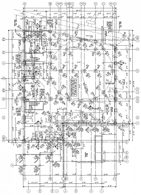
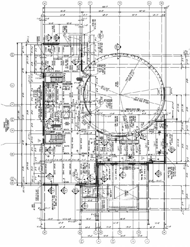
8 Figure 2: Installation of lecture hall structure Figure 3: Detail of lecture hall floors, as noted in S5.22 For the lecture hall, 8" grout filled CMU was used to support the stepped composite floor deck. This slab is a 4.75" thick slab, and the circular CMU walls rest on a 5.5" composite floor deck. This part of the building has a much larger substructure of wide flanges, most of which are greater than 150 pounds per linear foot. There is no typical bay type for this section of the floor structure either. FRAMING SYSTEM All of the framing for the Claude Moore Building was done with steel wide flanges. The beams, as previously mentioned, unfortunately do not follow much of a typical plan for size or spacing, but one should note that very minimal deviations were made as far as fitting the structure of the drum area into the rectangular structure of the rest of the building. A larger picture for reference is located in Appendix D. The columns are mostly 12" deep wide flanges; however the weights and spacings vary greatly within that. Because of the irregularity in the framing system, several transfer girders were necessary to allow for the change in structure from floor to floor. Most of these transfers happen below the first floor, and allow for the load to move from the main structure to the structure below grade. Page 8

9 LATERAL RESISTING SYSTEM The lateral resisting system for this project is mostly made up of moment frames. Originally, the intent was to use only moment frames, with limited X-bracing to react with the curtain wall system. Changes were made, however, when the owner and architect modified the design, and limited the space enough that other options had to be considered. As a result, the system is a hybrid of moment frames, Xbracing, and shear walls. The bays that include X-bracing are shown below. The east wall braces are made of HSS 4x4x3/16 sections, and the south wall employs several different sizes, but they are all HSS sections as well. The loads applied to these systems are transferred to the cast in place concrete foundation wall below, using a bolted base plate connection. In addition to these braced frames, two 14' long 12" CMU shear walls (red) were added at the plan southwest and southeast corners of the building. These walls help for shear in the north-south direction, and transfer their loads directly to the basement foundation below. The moment frame lies along column lines J and M, and is connected using welded and bolted angle plates of varying sizes to resist the moment. Page 9
10 Figure 4 (above): Framing plan including highlights of non momentframe lateral resisting elements. Detailed in S1.14. Figure 5 (left): Elevation of X-bracing between column lines 3 and 5.9 as detailed in S5.31. DESIGN CODES According to sheets S0.11 and A0.02, the following major code regulations were applied to this project: IBC 2003 with VA amendments (Virginia Uniform Statewide Building Code) IFC 2003 with VA amendments (Virginia Statewide Fire Prevention Code) IMC 2003 International Mechanical Code IPC 2001 International Plumbing Code ANSI/ASME A17.1 Safety Code for Elevators and Escalators Local ordinances and amendments to all of the above codes ACI Structural Concrete Building Code Page 10
11 AISC Manual of Steel Construction, 9th edition ASCE 5-02, 6-02 Code Requirements and Specifications for Masonry Structures ASCE 7-02 Minimum Design Loads for Buildings These code standards vary from the ones used in this report, and from the ones that will be used in future reports. These differences will result in variations between the report results, and the results used in the building design. MATERIALS USED The following is a breakdown of the structural materials used throughout the building as taken from S0.11 Use W Sections Channels, Angles, & Plates Hollow Structural Sections Steel Pipe Section Structural Bolts Welding Electrodes Anchor Bolts Headed Shear Studs for Composite Beams STEEL Class ASTM A992 GR 50 ASTM A36 ASTM A500 GR B ASTM A53 GR B Type E or S ASTM A325 and A490 -ASTM F1554 GR 36 ASTM A108 Strength psi psi psi psi n/s E70xx psi psi Designed for 11.4k per stud Page 11
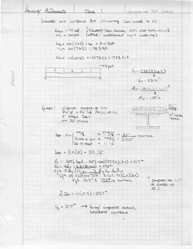
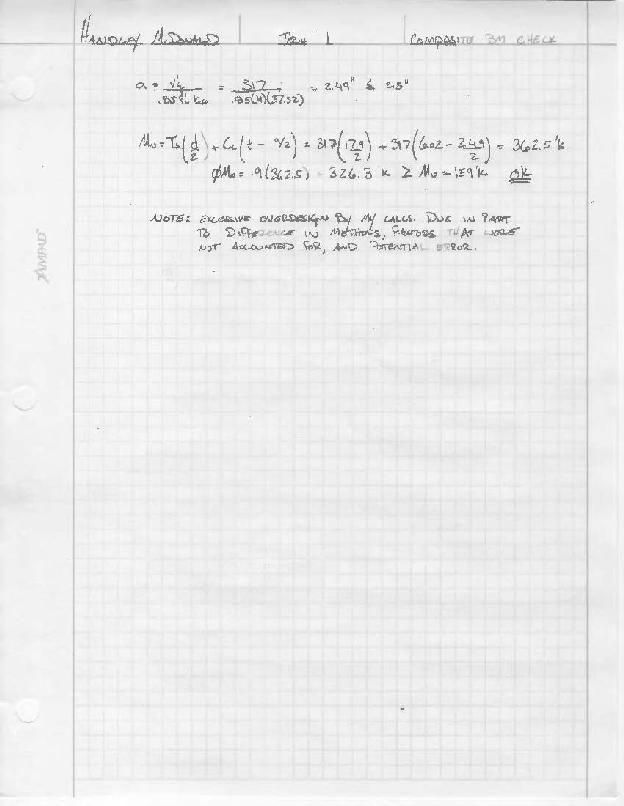
12 Use Slab on grade, cast in place walls & foundations Elevated Floor Slabs Reinforcing Steel Welded Wire Fabric Use Lightweight CMU Mortar for CMU Structural Grout Vertical Reinforcement Horizontal Joint Reinforcement CONCRETE Class Normal Weight (Assume 150 lb/ft3) Light Weight (Assume 100 lb/ft3) ASTM A615 GR 60 ASTM A185 MASONRY Class ASTM C90 GR N-1 ASTM C270 Type S ASTM C476 ASTM A615 GR 60 ASTM A82 w/ galvanizing per ASTM A 153 class B-2 Strength 4000 psi 4000 psi Fy=60000 psi Fy=60000 psi Strength f'm=1500 psi f'c=1800 psi f'c=2500 psi fy=60000 psi n/s SOILS Use Bearing Capacity Bedrock Bearing Disintegrated Rock Bearing Side Friction Strength 3000 psf standard bearing case 50 ksf for drilled piers 25 ksf for drilled piers 2 ksf for elevation below 450' above sea level GRAVITY LOADS As an exercise in structural analysis, this report includes a basic spot check of a composite beam in as much a typical bay is found in this frame. Also in this section are estimates of dead loads for the building materials, and live loads that were used in the design, per Sheet S0.11 DEAD AND LIVE LOADS The following is a list of the loads used in the calculations, and as specified in S0.11. Dead Loads: Actual weights of materials were used for the design of the building. Calculations used estimates of building material weights. A table with the estimates for these loads by floor is in Appendix C. Page 12
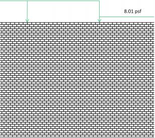
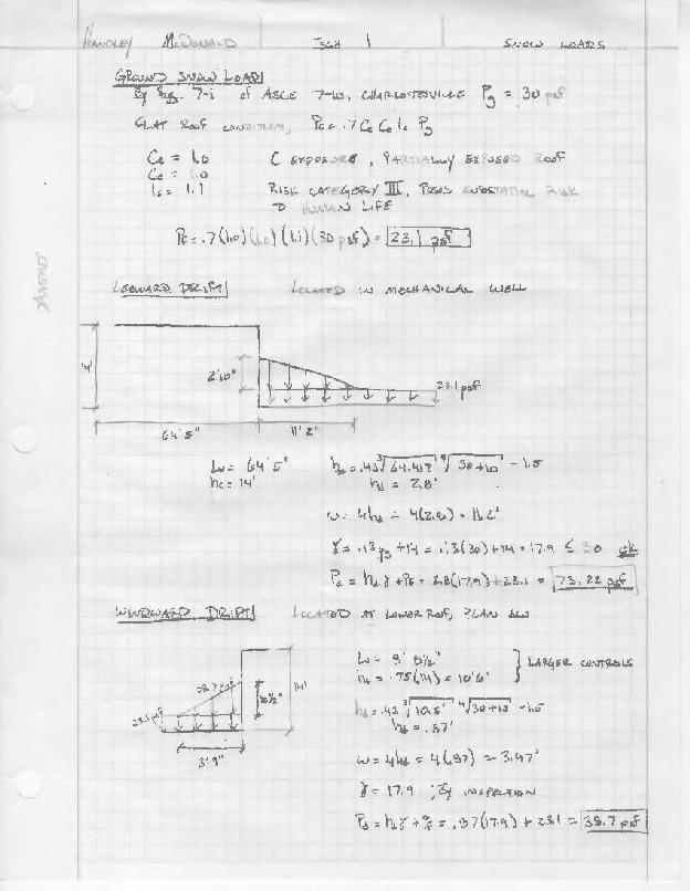
13 Live Loads: USE LOAD Roof live load 30psf unreduced Assembly and large lecture halls 100psf Terrace level roof at 2nd level 100psf Stairs, corridors, lobbies, and exitways 100psf Classrooms and training rooms 100psf* Offices and conference rooms 100psf* File storage 250psf Mechanical equipment room (penthouse) 150psf or equipment weight Slab on grade at basement level 200psf All other floor areas 100psf* *Indicates areas designed for greater load than code minimum. These greater loads allow for flexibility in future use of the space. SNOW LOADS The snow loads for this project were calculated in accordance with ASCE 7-02 and provided on Sheet S0.11. However, this report will conduct calculations based on ASCE 7-10, which resulted in a flat roof load of 23.1psf, and the following drift loads. Calculations are located in Appendix A. Page 13


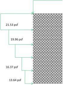
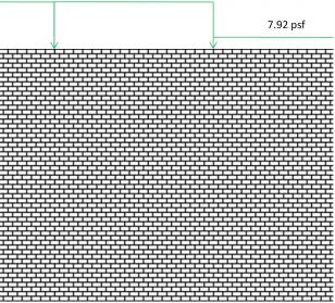
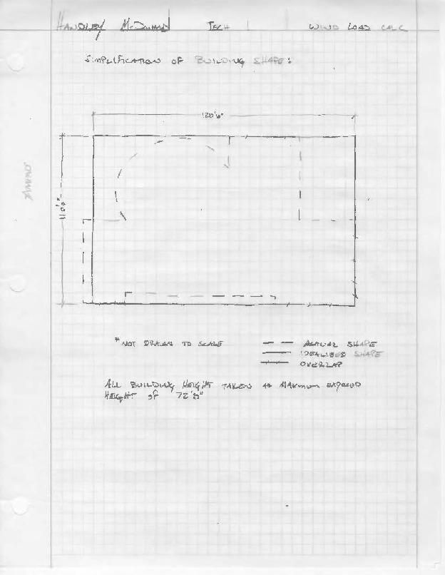
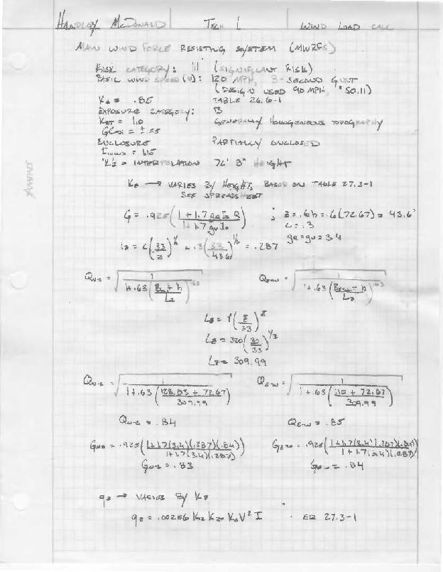
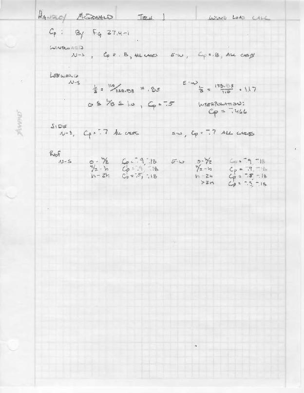
14 *Green space indicates the location of the mechanical well LATERAL LOADS Several hand calculations were made pertaining to the amount of lateral load on the building. An estimation of wind load was performed using a simplified building shape, and a seismic load calculation was done using the MWFRS method. WIND LOADS A derivation of the wind loads was calculated using ASCE 7-10, to determine what the maximum wind loads on the building are. The results are shown below, and supporting calculations can be found in Appendix B. A simplified shape was used to estimate the wind loads on the building using the MWFRS method. Page 14
15 Page 15

16 Page 16
17 Page 17
18 Page 18

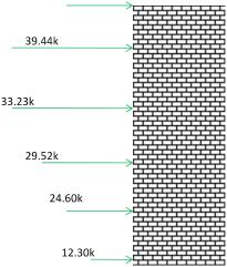
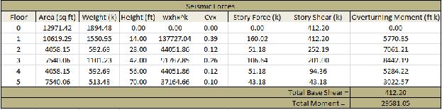
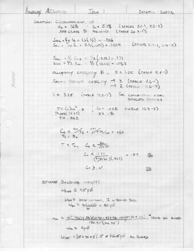
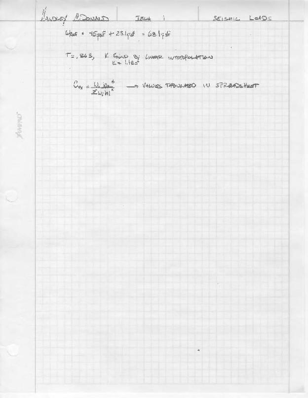
19 SEISMIC FORCES A derivation of the seismic loads on the structure was performed using the methods outlined in ASCE 705. The results are shown below, and the process can be found in Appendix C. 43k 51k 106k 51k 160k 412k ft-k Page 19
20 CONCLUSION Technical Report One was a review of the existing conditions of the Claude Moore Medical Education Building at the University of Virginia. Studies were done that included an overall review of how the framing, foundation, floor, and lateral system work together. Several design estimates and checks were also performed relating to the lateral load on the system, and gravity loads applied from dead, live, and snow loads. The gravity and snow loads derived appeared rather light, and as predicted, the seismic load provided the largest load to design for. This was only amplified by the fact that owner and architect changes to the design limited space for the lateral resisting system, and ultimately, other options were considered, until it resulted in the current system being employed. In performing these estimates, a good review of modern building code was established as well; however the building codes used for the building design differ greatly. Variations in results have occurred in this report, and will continue to occur in future studies. Page 20
21 APPENDIX A Page 21
22 Page 22
23 Page 23
24 Page 24
25 APPENDIX B Page 25
26 Page 26
27 Page 27
28 Page 28
29 APPENDIX C Page 29
30 Page 30
31 Page 31
32 Page 32
33 APPENDIX D Page 33
34 Page 34
35 Page 35