STANDARDS AND SPECIFICATIONS FOR THE CONSTRUCTION OF PUBLIC IMPROVEMENTS VOLUME II
|
|
|
- Tracy Hutchinson
- 5 years ago
- Views:
Transcription

1 STANDARDS AND SPECIFICATIONS FOR THE CONSTRUCTION OF PUBLIC IMPROVEMENTS VOLUME II POTABLE WATER DISTRIBUTION, SANITARY SEWER COLLECTION, AND NON-POTABLE IRRIGATION SYSTEMS JULY 2017 Adopted by Resolution No , July 19, 2017 TOWN OF HUDSON, COLORADO
2
3 TOWN OF HUDSON, COLORADO STANDARDS AND SPECIFICATIONS FOR THE CONSTRUCTION OF PUBLIC IMPROVEMENTS VOLUME II POTABLE WATER DISTRIBUTION, SANITARY SEWER COLLECTION, AND NON-POTABLE IRRIGATION SYSTEMS Page No. Design Criteria 7-64 Construction Specifications Construction Standard Drawings Appendix 265
4
5 POTABLE WATER DISTRIBUTION, SANITARY SEWER COLLECTION, AND NON-POTABLE IRRIGATION SYSTEMS DESIGN CRITERIA SECTION 1 - GENERAL REQUIREMENTS 1.01 Scope 1.02 Definitions and Abbreviations 1.03 Minimum Standards 1.04 Relationship to Other Standards 1.05 Review and Acceptance TABLE OF CONTENTS SECTION 2 - SUBMITTAL REQUIREMENTS 2.01 General 2.02 Preliminary Construction Plan Requirements 2.03 Final Construction Plan Requirements 2.04 Final Plat and Replat Requirements 2.05 Landscape Plans Requirements 2.06 Easements 2.07 Hydraulic Report - Potable Water & Sanitary Sewer 2.08 Design Report - Non-Potable Irrigation System 2.09 Geotechnical Soils Report 2.10 Verification Survey Drawing Requirements 2.11 As-Constructed Record Drawing Requirements 2.12 Reimbursement for Main Design and Installation Costs SECTION 3 - POTABLE WATER DISTRIBUTION SYSTEM DESIGN CRITERIA 3.01 General 3.02 Definitions 3.03 Design Flow 3.04 Pressure Requirements 3.05 Hydraulic Design 3.06 Potable Water Main Size 3.07 Depth of Bury 3.08 Connections to the Existing Potable Water System 3.09 Location and Looping of Potable Water Mains 3.10 Potable Water System Phased Installation and Stubouts 3.11 Pipe Material 3.12 Valves 3.13 Curved Pipe Alignment 3.14 Thrust Blocking and Pipe Restraint 3.15 Potable Water Main and Service Encasements 3.16 Potable Water Main Borings 3.17 Potable Water Services and Fire Sprinkler Lines 3.18 Potable Water Mains and Services in Relation to Other Utilities 3.19 Fire Protection and Hydrant Spacing 3.20 Cross Connection and Backflow Prevention Page No Page 1
6 SECTION 4 - SANITARY SEWER COLLECTION SYSTEM DESIGN CRITERIA 4.01 General Definitions Design Flow Infiltration and Inflow (I/I) Hydraulic Design Sanitary Sewer Main Size and Slope Depth of Bury Underdrains Location of Sanitary Sewer Collection Mains Sanitary Sewer Collection System Phased Installation and Stubouts Pipe Material Manhole Location and Size Manhole Inverts Groundwater Barriers Sanitary Sewer Main and Service Encasements Sanitary Sewer Main Borings Sanitary Sewer Services Sanitary Sewer Mains and Services in Relation to Other Utilities Wastewater Pumping Stations (Lift Stations) 50 SECTION 5 - NON-POTABLE IRRIGATION SYSTEM DESIGN CRITERIA 5.01 General Definitions Design Flow Pressure Requirements Hydraulic Design Non-Potable Irrigation Main Size Depth of Bury Connections to the Existing Non-Potable Irrigation System Location and Looping of Non-Potable Irrigation Mains Non-Potable Irrigation System Phased Installation and Stubouts Pipe Material Valves Curved Pipe Alignment Thrust Blocking and Pipe Restraint Non-Potable Irrigation Main and Service Encasements Non-Potable Irrigation Main Borings Non-Potable Irrigation Services Non-Potable Irrigation Mains and Services in Relation to Other Utilities Underground Marking Tape and Identification Non-Potable Irrigation Water Storage Facilities (Ponds) Shoulder Month Water Supply Water Wells Non-Potable Irrigation Pumping Systems Aeration Systems Water Dedication Requirements for Non-Potable Irrigation 64 Page 2
7 POTABLE WATER DISTRIBUTION, SANITARY SEWER COLLECTION, AND NON-POTABLE IRRIGATION SYSTEMS DESIGN CRITERIA LIST OF TABLES Page No. Table 3-1 Potable Water Design Flow 30 Table 3-2 Maximum PVC Pipe Joint Deflection 34 Table 3-3 Maximum DIP Pipe Joint Deflection 35 Table 3-4 Living Units Allowed Per Tap Size 38 Table 4-1 Sanitary Sewer Design Flow 42 Table 4-2 Minimum Sanitary Sewer Main Slopes 43 Table 4-3 Standard Manhole Diameter and Spacing 47 Table 4-4 Inside Drop Manhole Diameter 47 Table 5-1 Non-Potable Irrigation Daily Application Rates 54 Page 3
8 Page 4
9 SECTION 1 GENERAL REQUIREMENTS 1.01 SCOPE The purpose of the Town of Hudson Design Criteria and Construction Specifications, Volume III, Potable Water Distribution, Sanitary Sewer Collection, and Non-Potable Irrigation Systems, hereafter referred to as the "Criteria", is to present the minimum design and technical criteria for the analysis and design of potable water distribution, sanitary sewer collection, and non-potable irrigation systems for which Town of Hudson acceptance is required. The Criteria may be amended as new technology is developed or a need for revision is demonstrated and proven through experience and use. The Design Engineer shall be responsible for compliance with these Criteria as well as other applicable design and construction standards in the preparation of engineering reports, construction drawings, and specifications for Town review and acceptance DEFINITIONS AND ABBREVIATIONS Wherever the following words, phrases, and abbreviations appear in these specifications they shall have the following meaning: A. ac - acre B. ac-ft. - acre-feet C. ANSI - American National Standards Institute D. APPROVED PLAN - The latest revised Construction Drawing(s) accepted by the Town of Hudson. E. APWA - American Public Works Association F. AS-CONSTRUCTED DRAWINGS - Drawings reflecting actual conditions and information for the project after construction is completed. G. ASME - American Society of Mechanical Engineers H. ASTM - American Society for Testing Materials I. AWWA - American Water Works Association J. CDOT - Colorado Department of Transportation K. CDPHE - Colorado Department of Public Health and Environment L. cfs - cubic feet per second M. TOWN - Town of Hudson N. CONSTRUCTION DRAWINGS - Engineered working drawings including plan, profile, and detail sheets of proposed development and utility improvements accepted by the Town. O. CONTRACTOR - The individual, firm, partnership, corporation, or combination thereof, private, municipal, or public, including joint ventures, which, as an independent contractor, has entered into a contract with the Developer/Owner. SECTION 1 - GENERAL REQUIREMENTS Page 5
10 P. Q. R. S. T. U. V. W. X. Y. Z. AA. BB. CC. DD. EE. FF. GG. SECTION 1 CRITERIA - Town of Hudson Design Criteria and Construction Specifications, Volume III, Potable Water Distribution, Sanitary Sewer Collection, and Non-Potable Irrigation Systems. DESIGN ENGINEER - The partnership, corporation, or individual who is registered as a Professional Engineer, according to Colorado statutes, who is hired by the Developer/Owner to conduct engineering design services and may be empowered by the Developer/Owner to act as his agent for the project. DEVELOPER - The owner, corporation, association, partnership, agency, or individual who or which shall participate in development, has entered into a development agreement with the Town and has entered into an agreement with the Design Engineer and Contractor to perform the development work. DEVELOPMENT - Any construction or activity which changes the basic characteristic or use of land on which construction or activity occurs, including but not limited to, any non-natural change to improved or unimproved real estate, substantial improvements to buildings or other structures, installation of utilities, mining, dredging, filling, grading, paving, extraction, or drilling operations. DEVELOPMENT CODE - A section of the Town Municipal Code prepared by the Town of Hudson which sets forth requirements and standards for land development, land use, and the Subdivision Regulations. DIP - Ductile-iron pipe. EASEMENT - Shall mean a right granted by the property owner permitting a designated part or interest of the property to be used by others for specific use or purpose. EPA - Environmental Protection Agency ft 2 - square feet ft/s - feet per second GEOTECHNICAL ENGINEER - A partnership, corporation, or individual who is registered as a Professional Engineer, according to Colorado statutes, proficient in the area of soil mechanics, and who is hired by the Developer/Owner to conduct subsurface soils investigations and evaluations, ground water assessments, and other related engineering services. gpcd - gallons per capita per day gpd - gallons per day gpm - gallons per minute HP - horsepower INSPECTOR - Representative of the Town of Hudson designated to conduct construction/field observation. LAND SURVEYOR - A Registered Professional Land Surveyor, according to State of Colorado statutes, who is hired by the Developer/Owner to determine the boundaries and elevations of land and/or a structures and other related surveying services. MAY - A permissive condition. Where the word "may" is used, no requirement for design or application is intended. SECTION 1 - GENERAL REQUIREMENTS Page 6
11 HH. II. JJ. KK. LL. NEC - National Electric Code NFRWQPA - North Front Range Water Quality Planning Association (regional 208 agency) NON-POTABLE - Water that is not treated to approved drinking water standards and is not suitable or intended for human consumption, but is produced and delivered for irrigation use. OSHA - Occupational Safety and Health Administration OWNER - Any person having title or right of ownership in the surface estate of real property or leasehold interest within. MM. PGI - PVC Geomembrane Institute NN. OO. PP. QQ. RR. SS. TT. UU. VV. WW. XX. YY. ZZ. PLANNING COMMISSION - Appointed members to advise the Town Council on land use planning and development and to make decisions on land use matters. PLANS - See CONSTRUCTION DRAWINGS. PLC - Programmable Logic Controller PROFESSIONAL ENGINEER - An engineer registered with the State of Colorado according to State of Colorado statutes. PROFESSIONAL LAND SURVEYOR - A land surveyor registered with the State of Colorado according to State of Colorado statutes. psi - pounds per square inch PVC - Polyvinyl chloride SDC - Town of Hudson Design Criteria and Construction Specifications, Volume 1, Streets. SDDC - Town of Hudson Design Criteria and Construction Specifications, Volume II, Storm Drainage. SDR - Standard Dimension Ratio (pipe outside diameter over minimum pipe wall thickness). SHALL - A mandatory condition. Where certain requirements in the design or application are described with the "shall" stipulation, it is mandatory that these requirements be met. SHOULD - An advisory condition. Where the word "should" is used, it is considered to be advisable usage, but not mandatory. Deviations may be allowed when reasons are given which show that the intent of the standard is met. SPECIFICATIONS - The construction specifications portion of the Town of Hudson Design Criteria and Construction Specifications, Volume III, Potable Water Distribution, Sanitary Sewer Collection, and Non-Potable Irrigation Systems. AAA. STANDARDS - The design criteria portion of the Town of Hudson Design Criteria and Construction Specifications, Volume III, Potable Water Distribution, Sanitary Sewer Collection, and Non-Potable Irrigation Systems. BBB. SUBCONTRACTOR - Any person, firm or corporation, other than the employees of the Contractor, who enters into contract with the Contractor, to furnish labor, materials, or labor and materials SECTION 1 - GENERAL REQUIREMENTS Page 7
12 CCC. SUBDIVISION REGULATIONS - A section of the Development Code prepared by the Town of Hudson, which contains requirements for various land use, land development, and subdivision processes. DDD. UNCC - Utility Notification Center of Colorado. EEE. UTILITY - Town of Hudson Utilities Department. FFF. UTILITIES - Shall mean all utilities, wet and dry, on site prior to the time of any design and development and all utilities proposed with design. Wet utilities shall include, but are not limited to potable water lines, sanitary sewer lines, non-potable irrigation lines, transmission gas lines, storm water lines, underdrains, ditches, and other runoff conveyance elements. Dry utilities shall include, but are not limited to electric lines, telephone lines, gas service lines, fiber optic lines, and cable television lines. GGG. VFD - Variable Frequency Drive HHH. UTILITIES DIRECTOR - Shall mean the Director of the Town of Hudson Utilities Department or their designated representative. III. WQCD - Water Quality Control Division of CDPHE 1.03 MINIMUM STANDARDS A. The Town of Hudson's has Subdivision Regulations and Development Code documents that can help define the various processes required for projects within the Town. B. The Town's review and acceptance will only be to determine if the plans and specifications conform to the Town's requirements. The Town's review and acceptance will not relieve the Developer, Design Engineer and Contractor from responsibility for any variation from the Town requirements or adequate design standards. The Town's review and acceptance shall not constitute any assumption of responsibility or liability for the design or construction. It is the intent and purpose of these standards and specifications to obtain high quality construction throughout, with the completed work complying with the Town standards and specifications. C. All vertical and horizontal control shall be based on the currently adopted Town of Hudson vertical and horizontal monumentation. Proposed reference monumentation shall be approved by the Town prior to survey. A list of approved monuments may be obtained from the Town RELATIONSHIP TO OTHER STANDARDS A. Whenever a provision of these Criteria, and any other provision in any law, ordinance, resolution, rule, policy, or regulation of any kind contain any restrictions covering any subject matter within these Criteria, the most restrictive standard shall apply. B. The provisions of these Criteria and standards are minimum requirements that do not preclude the use of more restrictive standards by the Design Engineer. C. Adherence to these Criteria does not remove the Developer's responsibility to investigate and obtain any other regulatory permits or approvals, from either local, regional, state, or federal agencies, that may be required for a particular project. SECTION 1 - GENERAL REQUIREMENTS Page 8
13 1.05 REVIEW AND ACCEPTANCE A. All potable water, sanitary sewer, and non-potable irrigation construction plans and specifications submitted to the Town for review, comment, and acceptance shall be prepared by, or under the direct supervision of a Professional Engineer. Said Professional Engineer shall be responsible for the design, preparation of the construction drawings and reports, determining material specifications, and reviewing the field survey for accuracy. B. The construction plan review process for all development as outlined in the Subdivision Regulations shall be followed. 1. The preliminary plan set shall be reviewed by the Town for general compliance with these Criteria and the Town shall provide comments to the Developer or their agents regarding corrections, additions, and omissions. 2. Upon preliminary acceptance by the Planning Commission, final plats and Construction Drawings shall be prepared by the Developer or their agents. Final plats and Construction Drawings shall be submitted to and reviewed by the Town and the Town shall provide comments to the Developer or their agents for corrections, additions, or omissions. 3. After final corrections are made and the plans are accepted, the plans set shall be signed by the Utilities Director. The signing of the plans will constitute acceptance. The acceptance is qualified in that: The plans are reviewed and accepted for concept only and the plan acceptance does not imply responsibility by the Utilities Department or the Town of Hudson for accuracy and correctness. The plans acceptance does not imply that quantities of items indicated on the plans are the final quantities required. The plans acceptance shall not be construed for any reason as acceptance of financial responsibility by the Water and Sewer Department or Town of Hudson for additional items not shown that may be required during the planning or engineering phase and the construction phase. C. If the Design Engineer responsible for the plans disagrees with any requested changes to the submitted plans that may be required by the Town for acceptance, such disagreement shall be brought to the attention of the Town, and if required by the Town, in writing. D. The Seal of the Design Engineer on plans so corrected and accepted for construction will signify that the Professional Engineer has reviewed, approved, and authorized said corrected plans for construction. E. No construction shall be undertaken without a Town accepted and signed set of Construction Drawings and a recorded plat or required potable water, sanitary sewer, and/or non-potable irrigation exclusive easements. SECTION 1 - GENERAL REQUIREMENTS Page 9
14 Page 10
15 SECTION 2 SUBMITTAL REQUIREMENTS 2.01 GENERAL Requirements discussed in this section are the minimum for potable water distribution, sanitary sewer collection, and non-potable irrigation systems and are not meant to be all-inclusive. Other requirements may be needed for a complete design. The Design Engineer shall consider the maintenance and operational aspects of the potable water distribution, sanitary sewer collection, and non-potable irrigation systems' infrastructure, as well as, constructability in their design. A. The Utilities Department shall be contacted at the beginning of the project planning stages to determine if raw water requirements need to be met prior to Construction Drawing acceptance. Contact the Utilities Department at to discuss raw water requirements. B. All construction drawings shall be legible and submitted on 24" x 36" sheets. C. A legend describing all line types, symbols, and abbreviations shall be shown either on the cover sheet or each individual sheet. D. Each sheet in the Construction Drawings shall be marked "PRELIMINARY, NOT FOR CONSTRUCTION" with the date of submittal. This statement will be removed on the final Town accepted Construction Drawings. E. All sheets pertaining to potable water distribution, sanitary sewer collection, and non-potable irrigation systems (including but not limited to the title sheet, utility plan, conduit plan, plan and profile sheets, notes and details sheets, and landscaping plans) shall contain an acceptance block for the Utilities Director's acceptance, which shall appear as follows: CONSTRUCTION MUST BE IN ACCORDANCE WITH APPLICABLE TOWN OF HUDSON CONSTRUCTION STANDARDS. THE TOWN'S ACCEPTANCE ALLOWS FOR PLAN DISTRIBUTION AND PERMIT APPLICATION. THE TOWN'S ACCEPTANCE SHALL NOT RELIEVE THE DESIGN ENGINEER'S RESPONSIBILITY FOR ERRORS, OMISSIONS, OR DESIGN DEFICIENCIES FOR WHICH THE TOWN IS HELD HARMLESS. ACCEPTED BY: DATE: UTILITIES DIRECTOR F. Town accepted and signed construction plans are required prior to the Town's issuance of construction permits PRELIMINARY CONSTRUCTION PLAN REQUIREMENTS Preliminary plans shall be submitted to the Town for review and acceptance prior to the preparation of final Construction Drawings. Acceptance of the preliminary submittal shall constitute only a conceptual acceptance and shall not be construed as acceptance of specific design details. The preliminary plans set shall include the following: A. Cover Sheet 1. Project name and location. 2. A vicinity map specifying the project's geographical location with north arrow and adequate graphic scale and detail to be clear and uncluttered. SECTION 2 - SUBMITTAL REQUIREMENTS Page 11
16 3. Sheet index. 4. Name of Owner and Developer. 5. Name of the Design Engineer responsible for the design and preparation of the Construction Drawings and the Land Surveyor responsible for the project survey information. 6. Town recognized project benchmarks and two (2) horizontal control points to serve as the basis of the project horizontal control. 7. General Project notes from the A2 - Final Construction Plans Checklist in the Appendix, applicable for preliminary design. 8. Any additional information deemed necessary by the Design Engineer or Town. B. Utility Plan 1. A general overview of the entire project including, but not limited to, streets (complete with names), alleys, lot and block numbers, all proposed and existing utilities on and within 100 feet of the project site, all existing and proposed easement, rights-of-way on and adjacent to the project site, and storm water facilities. 2. The entire project shall be shown on one (1) sheet unless the project is too large to show sufficient detail. Town acceptance must be granted to show the project on more than one sheet and a key map to aid in drawing orientation and locating the sheet construction in relation to the overall project will be required on each sheet. 3. Proposed project phasing for utilities and structures. 4. Proposed point(s) of connection for potable water, sanitary sewer, or non-potable irrigation mains to the existing system(s). All existing potable and non-potable water lines shall be labeled with the pipe diameter, type of material, and year of installation (available from the Town). All existing sanitary sewer lines shall show existing manholes, complete with rim and invert elevations, and pipe diameter. 5. Any other information deemed necessary by the Design Engineer or Town FINAL CONSTRUCTION PLAN REQUIREMENTS Final Construction Plans shall contain the same information as indicated in the Preliminary Construction Plan Requirements Section 2.02 of these Criteria with the following additional requirements: A. After one (1) year from the original acceptance date, the Town may require resubmittal of the plans for review and acceptance due to revised or updated Town design criteria or construction specifications. B. Town accepted easements or a Town accepted final plat must be executed before final Construction Plan acceptance. C. One set of reproducible Mylar or vellum plans shall be submitted to the Town for acceptance signatures when all known issues have been addressed to the satisfaction of the Town. Once the Mylar/vellum plans receive Town signatures, the Developer or their agents shall make copies of the signed Mylars/vellums and provide them to the Town. SECTION 2- SUBMITTAL REQUIREMENTS Page 12
17 D. E. F. G. H. I. An electronic version, in a format acceptable to the Town, of the final Construction Drawings shall be provided to the Town at the time of Mylar/vellum plan signatures. Potable water, sanitary sewer, and non-potable irrigation main designs shall be provided on separate plan and profile sheets specific to potable water, sanitary sewer, and non-potable irrigation. The Utility Plan shall contain a signature line for all utilities that are impacted or modified by the project. This shall include existing as well as proposed utilities. The Utility Plan shall contain a signature line for all Ditch Companies, or end user(s) if the ditch is not controlled by a Ditch Company, that have their facilities impacted or modified by the project. "Call Utility Notification Center of Colorado (UNCC) at or dial 811 for utility locates 48 hours prior to any excavation work" shall be put on all drawing sheets. Conduit Plan 1. The conduit plan serves to show all proposed utility conduits crossing public rights-of-way and easements. The conduit plan is a separate sheet from the utility plan. 2. Provide a general overview of the project including but not limited to street names, street rightsof-way, all proposed and existing utilities, all proposed and existing easements, and lot and block numbers. 3. Show all utility conduits crossing the public rights-of-way and easements and indicate the utility conduit diameter, number of conduits, depth of installation, and name of utility using the conduit. 4. A signature line for all utility companies with utility conduits crossing public rights-of-way or easements. 5. Add the following note to the conduit plan: "All utility conduit crossings of potable water, sanitary sewer and non-potable irrigation lines shall be encased in High Density Polyethylene (HDPE) Pipe, with minimum Standard Dimension Ratio (SDR) 11 across the entire easement or right-of-way width. The encasement joint shall be butt fused. Flexible joints are not allowed." J. Construction Plan View 1. A key map shall be required on each sheet to aid in drawing orientation and locating the sheet construction in relation to the overall project. 2. Provide a north arrow and horizontal graphic scale. 3. A design horizontal scale of not less than 1" = 50'. 4. Provide existing and proposed roads and alleys complete with names. 5. Label proposed lot and block numbers. 6. Provide existing wet and dry utilities including potable and non-potable water line pipe material, diameter and year of installation, and sanitary sewer manhole inverts and pipe diameter. 7. Show and label proposed and existing easements, rights-of-way, and property lines. 8. List the name of adjacent developments or lots and their property owners. SECTION 2 - SUBMITTAL REQUIREMENTS Page 13
18 9. Indicate the proposed method of connection to existing potable water distribution, sanitary sewer collection, and non-potable irrigation systems. 10. Show all proposed and existing potable water, sanitary sewer, and non-potable irrigation services. Indicate the station of service locations on the potable water, sanitary sewer, and nonpotable irrigation mains or include a tabular list of stations. 11. Provide linear stationing along the potable water, sanitary sewer, and non-potable irrigation mains. 12. Provide match lines indicating references to adjacent sheet(s) of design. 13. Where the minimum cover over sanitary sewer mains provides less than nine (9) feet of elevation difference between the finished lot grade at building line and the top of the sewer main, a note shall indicate that the lot is served by a "shallow sewer" and appropriate elevation information shall be provided. Shallow sewer is defined in Section 4 of these Criteria. K. Construction Profile View 1. Provide the design vertical scale of not less than 1" = 10'. 2. Show all existing and proposed utility crossings. Existing utility crossing locations and elevations shall be obtained from the current project design field survey. Existing utilities shall be potholed as required to perform complete and accurate design prior to construction plan acceptance. Field obtained elevations shall be provided on the Construction Drawings complete with when the field information was gathered, the exact location where it was collected, the firm that performed the potholing and surveying, and the date the survey was conducted. 3. Provide the diameter, type of pipe material, pipe class, length of pipe between all fittings and manholes for proposed and existing potable water lines, sanitary sewer lines, or non-potable irrigation lines. 4. Provide stationing for all potable and not-potable mainline appurtenances including but not limited to top of pipe elevations on proposed fittings, valves, and points of vertical deflection. 5. Provide pipe slope, manhole inverts in and inverts out (main and service line), and rim elevations and manhole stationing for proposed sanitary sewer lines. 6. Provide match lines indicating references to adjacent sheet(s) of design. 7. Any other information deemed necessary by the Design Engineer or Town. L. Standard Drawing (Detail) Sheets 1. Include all project applicable Town of Hudson Standard Drawings as part of the construction plans set. Utilities Department Standard Drawings are provided in these Criteria. Refer to the Department of Public Works' SDC and SDDC, latest revision, for other project related details. 2. All Town of Hudson Standard Drawings shall contain the Town logo in the bottom left corner. If any standard Town detail is modified, the Town logo shall be removed from the detail. 3. Where Standard Drawings are not applicable to the work, provide project specific construction details. These shall include construction details of critical connections, atypical crossings, SECTION 2 - SUBMITTAL REQUIREMENTS Page 14
19 special fittings and appurtenances, and any other details deemed necessary by the Design Engineer or Town. M. Requirements for Changes to Final Accepted Plans 1. Should circumstances warrant changes from the Town accepted Construction Plans, acceptance of the changes shall be obtained from the Town. 2. All modified drawings shall be on 24" x 36" sheets. Depending on the extent of the changes, the Town will decide if revised Mylars/vellums are required or if paper copies are sufficient. N. Wastewater Pumping Station (Lift Station) Final Construction Plans Lift station final construction plan requirements are specific to the design requirements of the lift station in addition to state and regional guidelines. Refer to Section 4 for lift station requirements. O. Underdrain Final Construction Plans Underdrain final construction plan requirements can be obtained from underdrain design criteria and specification provided in Section 4 of these Criteria and construction specification Section 02622, Pipe Underdrains FINAL PLAT AND REPLAT REQUIREMENTS A. Final plats shall adhere to the requirements set forth in the Town of Hudson Department Subdivision Regulations and the Department of Public Works' SDC, latest revision. The following requirements shall also apply: 1. Clearly show, label, and dimension newly dedicated and existing potable water, sanitary sewer, and non-potable irrigation easements. 2. Where minimum cover over sanitary sewer provides less than nine (9) feet of elevation difference between the finished lot grade at the building line and the top of the sewer main, the plat shall indicate that the lot is served by a "shallow sewer". Shallow sewer is defined in Section 4 of these Criteria. 3. All platted lots shall be adjacent to a public potable water distribution and sanitary sewer collection main. No potable water or sanitary sewer services shall cross lot lines. B. For all replats where lot lines or street locations change, all existing potable water, sanitary sewer, and non-potable irrigation mains, services, fire hydrants, fire sprinkler lines, etc. shall be relocated to their appropriate location or abandoned. Potable water distribution, sanitary sewer collection, and nonpotable irrigation system designs in this replatted area must conform to the current Town of Hudson Design Criteria LANDSCAPE PLANS REQUIREMENTS A. No plant material with mature growth greater than three (3) feet in height shall be planted within potable water, sanitary sewer, or non-potable irrigation easements. B. No shrubs shall be planted within five (5) feet or trees within ten (10) feet of potable and non-potable water meters, fire hydrants, sanitary sewer manholes, or potable water, sanitary sewer, and nonpotable irrigation mains and services. SECTION 2 - SUBMITTAL REQUIREMENTS Page 15
20 C. Clearly show and label all proposed and existing potable water and non-potable irrigation meter pits/vaults, mains and services, sanitary sewer mains and services, fire hydrants, and easements on thelandscape plans. D. Show and label all proposed water taps that will be used for landscape irrigation. E. Add Sections 2.05-A and 2.05-B of these Criteria as notes on the landscape plans EASEMENTS A. When it is not feasible for potable water, sanitary sewer, or non-potable irrigation main installation to be in a dedicated street right-of-way, the installation shall be made within a dedicated easement. The conditions for allowance of such an exception shall be determined for each individual case. The minimum easement width acceptable to the Town is as follows: 1. For a dedicated potable water, sanitary sewer, or non-potable irrigation main easement containing just one (1) main, the width shall be twenty (20) feet or twice the depth to the invert of the pipe, whichever is greater. This easement shall be for the exclusive use by Town of Hudson potable water, sanitary sewer, or non-potable irrigation mains. The easement name, which shall be "EXCLUSIVE WATER LINE EASEMENT", "EXCLUSIVE SANITARY SEWER EASEMENT" or "EXCLUSIVE NON-POTABLE IRRIGATION EASEMENT", and the easement width shall be labeled on the Construction Drawings and plat. 2. For a combined potable water and sanitary sewer easement, the total width shall be thirty (30) feet or twice the maximum depth to the invert of the potable water line plus twice the maximum depth to the invert of the sanitary sewer pipe, whichever is greater. This easement shall be for the exclusive use by the Town of Hudson. The easement name, which shall be "EXCLUSIVE WATER AND SANITARY SEWER EASEMENT" and the easement width shall be labeled on the Construction Drawings and plat. 3. Combined easement widths are required to be wider than the widths previously stated if nonpotable irrigation mains are to be included in the easement or if any line depth requires additional width to be able to safely excavate around the pipe without the use of a trench box. Combined easements shall be named "EXCLUSIVE" along with the type of the mains included within the easement. The easement name and width shall be labeled on the Construction Drawings and plat. Appropriate naming and width for combined easements shall be determined by the Town on a case by case basis. B. The mains within the easement shall be located a minimum ten (10) feet from the edge of the easement or equal to the depth to the pipe invert, whichever is greater. C. There shall be no detention ponds, berms greater than three (3) feet, permanent structures, fences, trees, shrubs with mature height greater than three (3) feet, or other obstructions that will impede the ability of the Town to adequately maintain and service the main(s) located within the easement. D. Easements not dedicated with a plat, shall be dedicated by separate document and recorded prior to Town acceptance of the Construction Drawings. Easement dedication by separate document shall include: 1. Easement Dedication Form. A Utilities Department easement dedication form shall be completed by the Developer. Standard easement dedication forms are available in the appendix. If a non-standard easement dedication is required and a non-standard easement dedication form is needed, the Town will provide a revised form for the non-standard situation. The completed easement dedication form must be signed by the property Owner and notarized. SECTION 2 - SUBMITTAL REQUIREMENTS Page 16
21 2. Exhibit Map. An exhibit map (8 ½" x 11") with sufficient description information to establish the legal boundary of the easement shall be provided. The exhibit map shall show and label all existing easements, property lines, and public rights-of-way. The Town may request additional information, not listed here, for the exhibit map. 3. A Written Legal Description of the dedicated easement boundary. 4. Funds for Recording. The Developer shall provide cash or a check made out to the WELD COUNTY CLERK AND RECORDER for the easement recording fees. The Town shall provide the recording fee sum once all easement documents are finalized. The Town does not provide the funds for recording easement documents. 5. Once the easement dedication documents are accepted by the Town and the recording fees have been provided in the appropriate amount, the Town shall have the easement documents recorded with Weld County HYDRAULIC REPORT - POTABLE WATER & SANITARY SEWER A hydraulic analysis for the potable water distribution and sanitary sewer collection systems for a given project shall be submitted by the Design Engineer, as a report, to the Town for review and acceptance. The report shall be accepted by the Town prior to final Construction Drawing acceptance. The hydraulic analysis report will be reviewed by the Town, along with the Construction Drawings, in the same review and acceptance process as outlined in Section 1of these Criteria. Projects that move forward to final design without a Town accepted potable water distribution and sanitary sewer collection system hydraulic analysis report are subject to possible design changes, including but not limited to, pipe re-alignment, upsizing, extensions, and additional stubouts. The objective of the hydraulic analysis report is to assist the Design Engineer with designing a project's potable water distribution and sanitary sewer collection systems to adequately serve peak demands while adhering to the design requirements set forth in these Criteria. For the potable water distribution system, the hydraulic analysis report serves as a tool for demonstrating the necessary number of connection points to the existing system for adequate water line looping, system reliability and required pipe sizing. For the sanitary sewer collection system, the hydraulic analysis report evaluates peak flow quantities, flow type, pipe capacity, and flow velocity and establishes appropriate pipe sizing. Non-potable irrigation system hydraulic and design reports are also required for projects utilizing nonpotable water for irrigation purposes, however, since non-potable irrigation systems are unique, the nonpotable hydraulic and design report requirements have been provided in Section 2.08 of these Criteria. The written hydraulic report shall include the following information: A. Title Page 1. Report title. 2. Project name and location. 3. The name, address, and phone number of the Owner, Developer, and Design Engineer that prepared the report. 4. Report preparation date. B. Engineer Certification Sheet SECTION 2 - SUBMITTAL REQUIREMENTS Page 17
22 1. The report shall be prepared by or under the supervision of a Professional Engineer, licensed to practice in the State of Colorado, possessing adequate experience in the design of potable water distribution and sanitary sewer collection systems. The report shall contain a certification sheet with the following statement to be signed and sealed by the Design Engineer: "I understand the Town's acceptance does not relieve the Design Engineer's responsibility for errors, omissions, or design deficiencies for which the Town is held harmless. Registered Professional Engineer (Affix Seal) C. D. Table of Contents Project Description and Location 1. Clearly state the location of the project. Provide a site vicinity map specifying the project's geographical location and the project area in acres. The project acreage shall be the same as on the project plat. 2. Clearly state the land use zoning, estimated number of residential lots or living units, commercial square footages, and the irrigated acreages. 3. Indicate if the project will be phased. Elaborate on the anticipated timing for each project phase and the phase's associated building and infrastructure construction. 4. For multifamily, commercial, or industrial developments, indicate if potable or non-potable water will be used for landscape irrigation. 5. Identify the locations of all potable water, sanitary sewer, and non-potable irrigation connection points to the existing systems. 6. Provide the pipe diameter, pipe material, and year of installation for the existing potable and non-potable water lines and the pipe diameter for the existing sanitary sewer lines. E. References and Appendices 1. Provide a page referencing all design criteria, resources, and modeling software used in preparing the hydraulic report. 2. Provide appendices as necessary to include modeling result printouts, copies of demand assumption data, and fire flow test results. 3. Hydrant flow tests results may be available from Hudson Fire Protection District. Obtained fire flow test pressures will be evaluated for use by the Town on a case by case basis. F. Potable Water System Report Requirements and Assumptions 1. Provide all used equations, demand assumptions, and essential design requirements, parameters, and constraints. 2. Indicate the software package(s) and version used for the water system modeling. 3. Indicate in which Town of Hudson potable water pressure zone the project is located. SECTION 2 - SUBMITTAL REQUIREMENTS Page 18
23 4. Provide calculations for estimated population, design flows, irrigated acreage, irrigation application rates, peaking factors, and any other necessary design calculations. 5. Provide hydrant fire flow and fire sprinkler system flow requirements. G. Potable Water System Analysis and Modeling 1. Modeling Scenarios a. Static. The static scenario shall establish the available water pressure for the site with no demands on the system and serves to check that pressure requirements are maintained. b. Peak hour demand plus fire flow. This scenario shall include peak hour domestic water use 1 demands plus fire flow 2. c. Peak hour demand plus fire flow with one (1) water connection closed. While using the determined potable water demands for the peak hour plus fire flow scenario, each connection to the existing potable water system shall be closed, in turn, and modeled. Fire flow shall be placed at a hydrant nearest to the closed connection. This scenario represents a worst-case water demand condition and shall only serve to demonstrate how the potable water distribution system within the development functions during this condition. It is acceptable to have the potable water system pressure and velocity requirements violated in this scenario only. d. Phasing. Water modeling shall be required for the incomplete potable water system as indicated per the planned phasing on the Construction Drawings, in order to demonstrate that peak hour demand plus fire flow can be met for the interim phased condition. The hydraulic report shall verify that a proposed potable water system can provide the required water demands for a given development, at an acceptable pressure, and meet the overall potable water system design requirements set forth in these Criteria. Upsizing water mains within a development as a means to increase water system capacity in lieu of making a connection to another water source, is not permitted. If the hydraulic water model demonstrates that a larger main is required to serve the phased condition than would be needed for the full build out condition, the Developer is required to install the larger pipe at his expense and is not eligible for pipe oversizing reimbursement from the Town when the larger pipe is no longer needed. e. Additional scenarios. The Town may require additional scenarios, adjustments to the fire flow placement, reservoir elevations, and existing system connections, revisions to the pipe and node schematic layout, and other model modifications as necessary to verify that the proposed potable water system will meet the design requirements and potable water demands of the development and the Town as a whole. At the Town's discretion, the existing or future potable water system beyond the limits of the proposed development may require modeling as part of the hydraulic analysis. 1 Domestic water use shall refer to all household and corresponding lot irrigation for single family and applicable multifamily residential potable water use. It shall also refer to all potable water use, including potable irrigation, for commercial and industrial uses. 2 Fire flow shall be inclusive of fire hydrant and fire sprinkler flow. Residential, commercial, or industrial developments requiring fire sprinkler systems shall have fire sprinkler demands, in addition to hydrant fire flows, placed in the hydraulic water model at appropriate node locations. SECTION 2 - SUBMITTAL REQUIREMENTS Page 19
24 2. Modeling Procedure a. Connections to the existing potable water distribution system are typically denoted as reservoirs with the same hydraulic grade elevation. The Town shall provide inflow pressure. b. Place estimated domestic water, fire sprinkler, and irrigation tap demands at appropriate node locations within the model as they relate within the project. c. Locate fire flow demands at hydrant locations according to the modeling scenarios in Section 2.07-G of these Criteria. The maximum allowable fire flow provided from any one (1) hydrant shall be 1,500 gpm. If the required fire flow exceeds 1,500 gpm, the next closest hydrant shall be used until the required fire flow is met. d. Depending on the location of the development, existing potable water system performance and reliability in the area, number of available potable water connections, and surrounding land uses, some of the project's proposed potable water connections may require modeling as a demand point or no connection instead of a water source. The Town shall provide additional outflow demands for a development on a case by case basis. H. Potable Water System Report Results 1. Provide a schematic layout of the potable water distribution system showing and labeling the reservoir connections, pipe network, and demand nodes as presented and analyzed for each water model scenario. 2. Provide a Reservoir Report for the static condition. The Reservoir Report shall include the following information: a. Reservoir Identification Label b. Elevation (ft.) 3. Provide Pipe Reports for all modeled scenarios. Pipe Reports shall include the following information. a. Modeled Scenario Title b. Pipe Identification Label c. Pipe Length (ft.) d. Pipe Diameter (in) e. Pipe Material f. Hazen-Williams Coefficient g. Pipe Control Status (open or closed) h. Pipe Velocity (ft./s) i. Upstream Calculated Pressure (psi) j. Headloss (ft.) SECTION 2 - SUBMITTAL REQUIREMENTS Page 20
25 4. Provide Junction/Node Demand Reports for all modeled scenarios. Junction/Node Demand Reports shall include the following information: a. Modeled Scenario Title b. Node Identification Label c. Node Elevation (ft.) d. Node Demand (gpm) e. Calculated Hydraulic Grade (ft.) f. Pressure (psi) I. Potable Water System Design Conclusions 1. Discuss hydraulic analysis results for all modeled scenarios. 2. Confirm that the pipe velocity and pressure requirements during the peak hour demand plus fire flow operating condition are met per Section 3 of these Criteria. 3. Discuss any potable water line oversizing required by the Town over and above what is necessary for the development's potable water needs. 4. For phased developments, discuss phased construction of the potable water distribution system and confirm that potable water pipes are sized appropriately to meet the peak hour plus fire flow demand velocity and pressure requirements during the interim condition. J. Sanitary Sewer System Design Requirements and Assumptions 1. Provide all used equations, demand assumptions, and essential design requirements, parameters, and constraints. 2. Indicate software package(s) and version used for sanitary sewer pipe analysis. 3. Provide calculations for estimated population, design flows, peaking factor(s), hydraulic design, infiltration, flow type, and any other necessary design calculations. K. Sanitary Sewer Systems Analysis and Modeling 1. If the development is phased, the sanitary sewer system shall be analyzed for full build out. This evaluation shall include the development's sanitary sewer flows and anticipated offsite sanitary sewer flows impacting the sanitary sewer system within the development. 2. Evaluate the development's sanitary sewer sizing for capacity to convey offsite flows. 3. Undeveloped areas shall have sanitary sewer flows calculated based on the current or anticipated land use or zoning of the property. 4. The Town may require additional analysis in order to further verify that the proposed sanitary sewer system will meet the design requirements and needs of the development and the Town. The Town will evaluate sanitary sewer system hydraulic evaluations on a case by case basis. SECTION 2 - SUBMITTAL REQUIREMENTS Page 21
26 L. Sanitary Sewer System Report Results 1. Provide a schematic layout of the sanitary sewer collection system showing and labeling all manholes, design points used for analysis, pipe slopes, and pipe sections. 2. Provide written calculations or printouts of software analysis results for each pipe evaluation including the following information: a. Pipe Diameter (in) b. Pipe Slope (%) c. Manning's n Value d. Pipe Discharge (ft. 3 /s) e. Pipe Flow Velocity (ft./s) f. Pipe Flow Depth (in) g. d/d (depth of flow/diameter of pipe) h. Maximum Capacity (ft. 3 /s) M. Sanitary Sewer System Conclusions 1. Discuss analysis results for all pipe evaluations. 2. Confirm that acceptable pipe velocities and flow depth criteria are met. 3. If design constraints arise and pipe velocity, flow depth, minimum allowable slope per pipe diameter, or any other Criteria requirements cannot be maintained, the Design Engineer shall provide the Town written explanation as to why the Criteria is violated, why the non-standard sewer system design should be accepted, and request a variance to the Criteria. Town acceptance is required for the variance. 4. Discuss any sanitary sewer main oversizing required by the Town over and above what is necessary for the development needs. 5. Indicate if the development is served by "shallow sewer." Shallow sewer is defined in Section 4 of these Criteria. 6. Discuss potential impacts that upstream developments may have on the sanitary sewer capacity through the proposed development. Explain the capacity issues within the development and the proposed solutions for resolving them. N. Supplemental Engineering Calculations 1. These calculations shall include but are not limited to pipe restrained lengths, external pipe load analysis, traffic loadings, casing pipe wall thickness, and air and vacuum release valve sizing. 2. Any calculations deemed necessary by the Design Engineer or Town. SECTION 2 - SUBMITTAL REQUIREMENTS Page 22
27 O. Wastewater Pumping Stations (Lift Station) Design Report Refer to CDPHE lift station design and approval guidelines, as referenced in Section 4 of these Criteria, for lift station design report requirements. P. The Town may require electronic copies of the hydraulic models be submitted DESIGN REPORT - NON-POTABLE IRRIGATION SYSTEM The objective of the non-potable irrigation system design report is to assist the Design Engineer with designing a non-potable irrigation system and storage facility to adequately serve peak season irrigation demands while adhering to the design requirements set forth in these Criteria. Refer to Section 2.07 of these Criteria regarding report review and acceptance. The non-potable irrigation system design report shall include, but is not limited to, the following information: A. Refer to Section 2.07 of these Criteria for Title Page, Engineer Certification Sheet, and Table of Contents requirements. B. Project Description and Location 1. Clearly state the location of the project. Provide a site map identifying the project area and location of the non-potable storage facility (pond), pump station, discharges/fill lines, and overflow works. 2. Indicate if the non-potable system will be phased. Elaborate on the anticipated timing of the project phasing and how it will affect the overall design and construction of the non-potable irrigation system. 3. If connecting to an existing non-potable irrigation system, identify locations of pipe connections. Provide the pipe diameter, pipe material, and year of installation of the existing main. C. References and Appendices 1. Provide a page referencing all design criteria, resources, and modeling software used in preparing the design report. 2. Provide appendices as necessary to include supplementary information. D. Non-potable Irrigation System Report Requirements and Assumptions 1. Provide all used equations, assumptions, design methodologies, essential requirements, parameters, and constraints. 2. Indicate any software package(s) and version used for the non-potable pipe system modeling. 3. Provide calculations for determining irrigated acreage, required storage volume, pond design including high and low operating elevations, watering requirements, application rates, and design flow. 4. Provide the number and type of pumps, motor horsepower, system head curves, head computations, discharge pressure, and any other pertinent information for the pump system design. SECTION 2 - SUBMITTAL REQUIREMENTS Page 23
28 E. Discussion Items 1. Discuss specific design features of the non-potable irrigation system and their requirements, including but not limited to, non-potable/potable water sources and means of delivery into the system, the lining and aeration system, pond shoreline treatment, overflow works, and pond design. 2. General design requirements for the pump station, including but not limited to, power and electrical requirements, control and monitoring systems, and building requirements. F. Non-Potable Irrigation System Analysis and Modeling The non-potable irrigation system shall be modeled for the static scenario and the design irrigation demands scenario. Refer to Section 2.07 of these Criteria for modeling procedures and report results requirement. G. Non-potable Irrigation System Design Conclusions 1. Discuss hydraulic analysis results for all modeled scenarios. 2. Confirm that the pipe velocity and pressure requirements during irrigation demand are met per Section 5 of these Criteria. H. The Town may require electronic copies of the hydraulic models be submitted GEOTECHNICAL SOILS REPORT A. A geotechnical soils evaluation, prepared by or under the supervision of a Geotechnical Engineer, licensed in the State of Colorado, shall be submitted to the Town for review and shall be accepted by the Town prior to final Construction Drawing acceptance. The geotechnical soils report shall describe the classifications and characteristics of the soils encountered on the project and include recommended methods of backfilling and compaction. Refer to the Department of Public Works' SDC, latest revision, for soils testing and geotechnical soils report requirements. B. The Geotechnical Engineer shall evaluate groundwater conditions for the site and provide recommendations for underdrains and sanitary sewer main groundwater barriers VERIFICATION SURVEY DRAWING REQUIREMENTS A. Prior to paving, the Design Engineer shall provide the Town with a survey of the installed potable water, sanitary sewer, and non-potable irrigation systems and, if required on the project, underdrains. The purpose of this survey is to verify that the mains and appurtenances were installed per design and within allowable construction tolerances. Once the Town has accepted the verification survey, the Town shall give the Contractor written notice to proceed with paving construction. Verification Survey plans are not As-Constructed Record drawings. See Section 2.11 of these Criteria for As- Constructed Record Drawing requirements. B. The Verification Survey drawing(s) shall be prepared for easy modification and transition to final As- Constructed Record drawings. C. The Verification Survey drawings shall be modified original construction plan and profile sheets showing the design information as well as the surveyed information. The original design information shall be shown as "lined through". The surveyed information shall be located in the same area as the design information and shall be either "clouded" or made with a heavier line weight than the design information for clear differentiation. SECTION 2 - SUBMITTAL REQUIREMENTS Page 24
29 D. Verifications Survey drawings shall be prepared by a Professional Engineer. Surveyed elevations for the Verification Survey shall be obtained by a Colorado Registered Land Surveyor. The Surveyor shall obtain horizontal locations, surveyed elevations, and information for the following: 1. Potable and non-potable - Horizontal locations of valves, fire hydrants, blow-offs, air/vacuum release valves, and top of pipe elevations at all valves. 2. Sanitary sewer - Horizontal locations of manholes, sizes of installed pipe, invert elevations of all mainline pipes and services entering and exiting a manhole, distances between manholes, pipe slopes based on the surveyed invert elevations, and proposed manhole rim elevations. 3. Utilities - Provide horizontal and vertical location of all existing and proposed utility crossings. 4. Underdrains - Provide horizontal locations of cleanouts. 5. For potable and non-potable water lines, provide the proposed final ground elevations at all valve boxes. Surveyed top of valve nut elevations must be calculated to top of pipe elevation based on the height of the installed valve bonnet, which varies due to pipe diameter and valve manufacturer. 6. Any other surveyed information as required by the Town. E. Construction tolerances shall be: 1. Horizontal locations: ± 0.30 feet 2. Elevations: ± 0.30 feet F. A completed A5 - Verification Survey Checklist and Certification form found in the Appendix, shall accompany the submitted Verification Survey plans AS-CONSTRUCTED RECORD DRAWING REQUIREMENTS A. The Contractor and Design Engineer shall be responsible for recording As-Constructed information on a set of Record Drawings kept at the construction site. A representative of the Developer shall monitor construction to assure that changes in construction (as approved in writing) and other pertinent details, such as horizontal location of fittings and manholes, valves, top of pipe elevations, manhole inverts, service tap locations, pipe sizes, depths, etc. are kept current on the As-Constructed Record Drawings. B. Where the construction is phased with a more than 30-day lapse between phases, As-Constructed Record Drawings shall be submitted to the Town after each completed phase. The Construction Drawings for all future phases shall also reflect the "As-Constructed" conditions of the previous phases. C. At a minimum, the As-Constructed Record Drawings set shall include the following sheets from the original accepted Construction Drawings: 1. Cover Sheet 2. Utility Plan 3. All potable water, sanitary sewer including underdrains as required on the project, and non-potable irrigation plan and profile sheets. SECTION 2 - SUBMITTAL REQUIREMENTS Page 25
30 4. All construction details and Town of Hudson Standard Drawings that were used in the construction of the potable water distribution, sanitary sewer collection, and non-potable irrigation. D. The As-Constructed Record Drawings shall show the original design information as well as the As- Constructed information. The original design information shall be shown as "lined through". The As- Constructed information shall be located in the same areas as the design information and shall be either "clouded" and/or made with a heavier line weight as the design information for clear differentiation. The month and year of the construction shall also be noted. E. A Colorado Registered Land Surveyor shall certify the As-Constructed horizontal locations and surveyed elevations of all items listed in Section 2.10 of these Criteria in addition to: a. Final sanitary sewer manhole rim elevations. b. Final top of water valve box elevations. c. Construction tolerances shall be: 1) Horizontal locations: ±0.30 feet 2) Elevations: ±0.30 feet F. The project responsible Design Engineer and Land Surveyor shall observe construction, as required, in order to certify that the conditions and information recorded on the As-Constructed Record drawings is true and correct. G. The General Contractor for the project shall sign each drawing sheet of the As-Constructed Record plans set with the following statement: I,, hereby state that this project was constructed to Town of Hudson accepted Construction Drawings and standards, as designed by the project Design Engineer, and as field staked by the project Land Surveyor. All deviations to the approved Construction Drawings, standards, design, or survey were so noted on field drawings and these were provided to the project Design Engineer for acceptance and inclusion in the As-Constructed Record Drawings. Construction Company Address Authorized Representative Title Date SECTION 2 - SUBMITTAL REQUIREMENTS Page 26
31 H. A Professional Land Surveyor shall perform or directly supervise all field survey data collection to verify the As-Constructed conditions and shall stamp and seal each drawing sheet in the As-Constructed Record Drawing set with the following statement: I,, hereby state that this project was field staked for construction per Town of Hudson accepted Construction Drawings and standards and in accordance with the project design. I certify that the field survey information obtained for the As-Constructed Drawings was obtained in accordance with Town current standards and is accurately represented on these As-Constructed Record Drawings. Registered Professional Land Surveyor (Affix Seal) I. A Professional Engineer shall review all the As-Constructed information for compliance with the original approved design and standards and shall stamp and seal each drawing sheet in the As- Constructed Record plan set with the following statement: I,, hereby state that I have reviewed the As-Constructed information provided by the project Contractor and project Land Surveyor. I certify that according to the information provided the As-Constructed Record Drawings are in compliance with the Town of Hudson accepted Construction Drawings and standards and will function as designed. Registered Professional Engineer (Affix Seal) J. As-Constructed Record drawings shall be submitted to the Town prior to issuance of Substantial Completion. The two (2) year warranty period for the installed potable water, sanitary sewer, and non-potable irrigation systems will begin after the Certificate of Substantial Completion has been issued by the Town. The request for the Substantial Completion Certificate may be initiated by the Town or requested by the Developer, but in all cases, is the sole responsibility of the Developer. K. The Town will compare the certified As-Constructed Record Drawing information with the approved Construction Drawings, previously submitted Verification Survey, and information the Town may be aware of during the construction process. Any corrections, additions, or omissions to the As-Constructed Record Drawings shall be provided to the Design Engineer who prepared the As-Constructed Drawings for changes. L. The Certificate of Final Acceptance, which occurs at the end of the warranty period, will NOT be granted until the As-Constructed Drawings for the potable water, sanitary sewer, and non-potable irrigation systems are accepted by the Town. (Ordinance 44, 2002) 2.12 REIMBURSEMENT FOR MAIN DESIGN AND INSTALLATION COSTS A. The Town may require the Developer to install a potable water, sanitary sewer, or non-potable irrigation main larger than is needed to adequately serve the development. B. The Town will reimburse the Developer for the materials costs above that required for the development. The difference in materials costs shall only include the difference in pipe materials, manhole materials, valve materials, and fitting materials. Additional materials costs, if any, shall be agreed upon, in writing, prior to commencement of construction. SECTION 2 - SUBMITTAL REQUIREMENTS Page 27
32 C. For sanitary sewer collection main over sizing, the Town may reimburse the Developer for extra depth costs due to additional sanitary sewer main installation excavation above that required for the development. D. If Town requested oversizing results in significant change to horizontal or vertical alignment, additional reimbursement may be agreed to prior to construction. E. The Developer shall submit a materials list with unit prices, quantities, and a cost comparison between the two pipe sizes under consideration. Reimbursement will be paid only after the As- Constructed Record Drawings have been accepted by the Town. Copies of material invoices for materials delivered to the development site and used in construction shall be provided along with the Developer's request for reimbursement. F. If the Developer is required to design and construct off site potable water, sanitary sewer, or non-potable irrigation mains in order to serve the development, the Developer may be eligible for design and construction cost reimbursements from other developments that connect to that main. Conversely, if the Developer connects to potable water, sanitary sewer, or non-potable irrigation mains constructed by another Developer or the Town, the Developer may be required to participate in the design and construction costs of those lines. SECTION 2 - SUBMITTAL REQUIREMENTS Page 28
33 SECTION 3 POTABLE WATER DISTRIBUTION SYSTEM DESIGN CRITERIA 3.01 GENERAL The purpose of this section is to provide information for the design and layout of a potable water distribution system. Potable water distribution system design shall be in accordance with these Criteria. This section is not intended to be inclusive of all situations and the Design Engineer may be required to use additional engineering judgment to meet the overall design intent for constructability and long-term operations and maintenance. This Design Criteria typically applies to potable water mains sixteeninches (16") in diameter and smaller. The Town of Hudson Utilities Director reserves the right to make final determinations of the system design based on the best interest of the Town's system DEFINITIONS A. Potable Water Distribution Mains 1. A potable water distribution main is a water pipe that primarily serves as a delivery conduit to transport potable water from transmission mains directly to individual water services. 2. Potable water distribution mains within the Town are eight-inches (8"), twelve-inches (12"), and sixteen-inches (16") in diameter. B. Potable Water Transmission Mains 1. A potable water transmission main is a water pipe that primarily serves as a delivery conduit to transport potable water directly to the distribution mains. 2. Potable water transmission mains are eighteen-inches (18") and larger in diameter. C. Potable Water Services Potable water services include all piping, fittings, and appurtenances used to convey potable water from the distribution main to the customer DESIGN FLOW A. The potable water distribution system shall be designed to transport peak hour plus fire flow demands in accordance with these Criteria. B. All water demands used in the design of potable water distribution systems are subject to approval by the Town. SECTION 3 - POTABLE WATER DISTRIBUTION SYSTEM DESIGN CRITERIA Page 29
34 C. Design Flow 1. The water demand criteria presented in the following table are minimum criteria and the Town reserves the right to modify the Criteria, at any time, for the design of specific projects. Potable water demand criteria for uses not provided in the table shall be determined during system design. TABLE 3-1: Potable Water Design Flow Residential Zoning based on Town of Hudson Code, Chapter 16, Zoning Districts. Use Units per Acre Occupancy Peak Hour Demand R persons 1.9 gpm/unit R persons 1.7 gpm/unit R persons 1.1 gpm/unit Commercial Commercial demands based on 1000 ft. 2 of building area. Use Average Day Demand Peak Hour Demand Office Building 0.14 gpm 0.60 gpm Restaurant 0.35 gpm 1.50 gpm Small Businesses 0.14 gpm 0.60 gpm Supermarket 0.14 gpm 0.60 gpm Big Box/Dept gpm 0.60 gpm Store Laundry, Dry 0.70 gpm 2.90 gpm Cleaning Service Station 0.02 gpm 0.08 gpm (No Car Wash) Car Wash 1.32 gpm 5.50 gpm Hotel/Motel 0.24 gpm 1.00 gpm Warehouse (Nonindustrial) 0.07 gpm 0.30 gpm Irrigation N/A 24 gpm/acre 2. Irrigation is included in the residential water demand, but not included in the commercial water demand. Irrigation demands for commercial uses shall be determined using the provided irrigation demand criteria and the commercial development's estimated irrigated acreage. 3. Potable water demands have not been provided for industrial uses. Due to the extreme variation in water consumption amongst the different types of industry, industrial water demands shall be determined during system design when the industrial use is known. D. Fire Flows 1. Contact Hudson Fire Protection District for the latest adopted fire code and to confirm project fire flow requirements. 2. For design purposes, the maximum allowable fire flow provided from any one (1) hydrant is 1,500 gpm. Fire flow may be obtained from more than one (1) fire hydrant providing the SECTION 3 - POTABLE WATER DISTRIBUTION SYSTEM DESIGN CRITERIA Page 30
35 additional hydrants are accessible to any possible fire location and meet the spacing requirements and distances from structures as specified in Section 3.19 of these Criteria and by Hudson Fire Protection District PRESSURE REQUIREMENTS Potable water distribution systems must be designed to provide minimum and maximum system pressures as discussed in the following sections. Water system pressure information for the Town's existing system may only be obtained from the Town. A. The potable water distribution system in all areas shall be designed for a maximum pressure of 125 psi and a minimum pressure of 40 psi for normal conditions. B. Twenty (20) psi residual pressure is required at any one (1) hydrant with peak hour demands. C. Pressure zones shall conform to existing Town of Hudson pressure zones as provided in the Water Master Plan, latest revision. Specific information on the pressure zones or to confirm which pressure zone a development or site is actually located may only be obtained from the Town. D. Pressure regulating valves (PRV) will be required between pressure zones. The PRV location shall be determined by the Town HYDRAULIC DESIGN A. Friction Coefficient Potable distribution mains shall be designed using a Hazen-Williams friction coefficient "C" equal to 120. B. Velocity All pipes shall be sized for a maximum water velocity of no greater than ten (10) feet per second (fps) at peak hour demand plus fire flow. C. Head Loss 1. Head loss in pipes twelve-inches (12") in diameter or less, at peak hour demand plus fire flow, shall not exceed ten (10) feet of head loss per 1,000 linear feet of pipe (10 ft./1,000 ft.). 2. For sixteen-inch (16") diameter pipes, head loss at peak hour demand plus fire flow shall not exceed three (3) feet of head loss per 1,000 feet of pipe (3 ft./1,000 ft.) POTABLE WATER MAIN SIZE A. Unless specifically indicated otherwise, sixteen-inch (16") mains are required every mile and twelve-inch (12") mains are required every half-mile. Other distribution mains shall have a minimum diameter of eight-inches (8"). B. Hydrant leads connecting to the potable distribution system shall be six-inches (6"). Other pipe diameters for hydrant leads are prohibited DEPTH OF BURY A. The minimum depth of cover shall be five (5) feet and the maximum depth of cover shall be six (6) feet. SECTION 3 - POTABLE WATER DISTRIBUTION SYSTEM DESIGN CRITERIA Page 31
36 B. When design or constructability constraints are present, deeper or shallower water main installation may be permitted only with acceptance from the Town. Additional design and installation considerations may be required by the Town depending on the situation CONNECTIONS TO THE EXISTING POTABLE WATER SYSTEM A. Main connections to the existing potable water distribution system may be made by wet tap or cut in tee. The Town shall make all twelve-inch (12") diameter or smaller wet taps on the existing system. It is the Contractor's responsibility to provide all tapping materials (tapping sleeves, tapping valves, insulator kit, etc.) when the Town is drilling the wet tap. B. All wet taps greater than twelve-inch (12") diameter and all cut in tees shall be made by the Contractor under the direct supervision of the Town. C. For direct wet taps on existing transmission mains or sixteen-inch (16") distribution mains, manufacturer's shop drawings and specifications for the proposed tapping sleeve shall be submitted to the Town for review and acceptance prior to installation of the tapping sleeve by the Contractor. D. Direct taps on existing transmission mains or sixteen-inch (16") distribution mains shall require the installation of an insulator kit between the tapping sleeve and tapping valve LOCATION AND LOOPING OF POTABLE WATER MAINS A. Potable water mains shall be located in the center of a dedicated street right-of-way, where feasible, or within a dedicated exclusive easement of appropriate width. If narrow street sections do not allow the water line to be located in the center of the street right-of-way while maintaining clearances from other utilities and the lip of street gutter, the Town will allow the potable water main to be located five (5) feet offset from centerline of the street right-of-way. Town approval is required for all other proposed potable water main locations. B. The centerline of potable water mains shall not be placed closer than eight (8) feet to the lip of street gutter without prior acceptance by the Town. C. Potable water mains serving a cul-de-sac shall be extended to within ten (10) feet of the lip of street gutter at the end of the cul-de-sac and shall have a hydrant assembly placed on the end of the line. D. A potable water main serving one (1) lot shall extend all the way across the frontage for that lot. E. Permanent dead-ends longer than 300 feet are prohibited. F. Temporary dead-ends shall have a hydrant blowoff at the end of the line. G. An adequate number of connections to the existing potable water distribution system shall be provided such that no more than fifteen (15) single family units, or the equivalent single family flow for nonresidential developments, are out of service at any one time. 1. Potable water mains shall extend to the extremities of the property or the subdivision served. Extensions shall be in appropriate locations to provide adequate water connections and to maintain looping requirements for adjacent, future developments and to facilitate the completion of the grid described in Section 3.06 of these Criteria. 2. Water mains shall be extended offsite when required to tie into the existing distribution system for additional water source connections. Appropriately sized easements shall be provided. SECTION 3 - POTABLE WATER DISTRIBUTION SYSTEM DESIGN CRITERIA Page 32
37 H. In all instances, the Town shall determine the potable water system looping for a development on a case by case basis and may require additional potable water connections over and above those demonstrated by a hydraulic analysis to maintain overall water system performance. Ultimately, the required source connections to the existing potable water system shall be solely determined by the Town POTABLE WATER SYSTEM PHASED INSTALLATION AND STUBOUTS A. Potable water distribution system phasing, if proposed by the Developer, shall be clearly identified on the master utility plan. Water plan and profile sheets shall clearly show and label the phasing transitions in the potable water line design. B. The proposed potable water system phasing shall maintain looping integrity within the system as described in Section 3.09 of these Criteria. C. The phased potable water system design shall meet the phased water demands for the development and adhere to all potable water system and hydraulic design requirements provided in these Criteria. D. Locate line valves and temporary hydrant blow-offs at the end of each phase or stubout. The stubout shall be shown on the potable water plan and profile sheets. E. Phased water line or stubout construction shall be extended a minimum ten (10) feet beyond phased street paving to avoid asphalt removal during excavation for future connections. F. Phased potable water mains or stubouts intended for future connections shall be valved such that only one (1) valve needs to be closed when the main is extended and no customers are without water service when the line is extended. The valve must be appropriately restrained so that it will not "blow off" when the water line is exposed and all thrust blocking is removed for the extension. See Section 3.14 of these Criteria regarding pipe restraint. G. The maximum length of a stubout shall be fifty (50) feet unless otherwise approved by the Town. H. Potable water main stubouts not utilized shall be abandoned. Refer to Appendix Section A9 - Policies Impacting Design and Construction for abandonment procedures PIPE MATERIAL A. Potable water pipes less than or equal to twelve-inches (12") in diameter shall be AWWA C151 cementlined ductile iron pipe or AWWA C900 polyvinyl chloride (PVC) pressure pipe. Sixteen-inch (16") potable water pipes shall be AWWA C151 cement-lined ductile iron. B. The Design Engineer shall specify the pipe material and class as required for specific project conditions. The pipe material and class shall be called out on the Construction Drawings. C. All ductile iron pipe shall be polywrapped in accordance with AWWA C VALVES A. All valves shall be located in dedicated street right-of-way or within a dedicated exclusive easement of appropriate width. Town approval is required for all other proposed valve locations. SECTION 3 - POTABLE WATER DISTRIBUTION SYSTEM DESIGN CRITERIA Page 33
38 B. Gate Valves 1. Gate valves are assigned in the potable water distribution system so that no single accident, break, or repair necessitates shutting down a length of pipe greater than 500 feet. 2. At street intersections, gate valves shall be located at the extension of property lines, wherever possible. 3. Gate valves shall be located a minimum five (5) feet from the edge of concrete cross pans. This requirement has precedence over Section 3.12-B.2 of these Criteria. 4. Fire hydrant and fire sprinkler line gate valves shall be placed at the main. These gate valves shall be mechanical joint valves and fasten to a mechanical joint anchor tee (swivel tee) on the main. 5. All potable water line valves shall have a concrete collar around the valve box in accordance with SDC Standard Drawings. C. Air Release, Air/Vacuum, and Combination Air Valves 1. Sixteen-inch (16") diameter mains shall have air release (AR) valves, air/vacuum (A/V) valves, or combination air valves installed at appropriate locations along the main and shall be properly sized by the Design Engineer in accordance with the manufacturer's recommendation. The Town shall have final determination on valve size, placement, and type of valve to install. 2. These valves shall perform the following operations: a. AR valves release accumulated air from a pipeline during filling operations and while the system operates under pressure exceeding atmospheric pressure. b. A/V valves release air automatically during pipeline filling and admit air automatically when the internal pressure in the pipeline drops below atmospheric pressure. c. Combination Air Valves perform the same functions as an AR valve and an A/V valve. D. Pressure Regulating Valves 1. Pressure regulating valves (PRVs) control pressures between potable water distribution system pressure zones. 2. The need for a PRV and its installation location shall be determined by Town. The standard PRV size is eight-inches (8") unless otherwise approved by the Town CURVED PIPE ALIGNMENT A. Potable water mains may be curved to change alignment or grade or to avoid obstructions, within the limits of curvature of the pipe. If a curved alignment is not feasible or permitted by the Town, an appropriate bend fitting shall be used. B. Allowable Joint Offset for PVC Pipe TABLE 3-2: Maximum PVC Pipe Joint Deflection Pipe Diameter (in.) Maximum Joint Deflection ( ) 8" " 1.5 SECTION 3 - POTABLE WATER DISTRIBUTION SYSTEM DESIGN CRITERIA Page 34
39 C. PVC pipe can be joined with High Deflection (HD) Couplings which allow five degrees (5 ) of pipe joint deflection per coupling. HD couplings can be used in the place of small bends or where it is undesirable or impossible to bend the pipe. D. Allowable Joint Deflection for DIP Pipe Table 3-3: Maximum DIP Pipe Joint Deflection Pipe Diameter (in) Maximum Joint Deflection ( ) 6" 4.0 8" " " THRUST BLOCKING AND PIPE RESTRAINT A. Thrust Blocks 1. Concrete thrust blocks shall be constructed at all mainline bends and tees. 2. The thrust block details, as shown in the Town of Hudson Standard Drawings, are to be used as minimums only. The Design Engineer shall determine the required size of thrust blocks to use. B. Pipe Restraint 1. If for any reason (i.e. temporary dead end line), concrete thrust blocks cannot be used, restrained push-on or mechanical joint restraints shall be required. 2. The Design Engineer shall determine the length of required pipe restraint, for the pipe material being used, PVC or DIP, in accordance with AWWA M41 Ductile-Iron Pipe and Fittings or AWWA M23 PVC Pipe - Design and Installation, latest revision. a. Restraint calculations shall be submitted to the Town for review and acceptance. b. Restrained length(s) shall be provided on the Construction Drawings. C. In some instances, (i.e. fire hydrants, large diameter fire lines, water line lowerings, etc.) thrust blocks may be required in addition to pipe restraint. The Town shall make such determinations on a case by case basis POTABLE WATER MAIN AND SERVICE ENCASEMENTS A. No general statement can be made to cover all encasement conditions; therefore only typical encasement situations are addressed in this section. Encasement requirements shall ultimately be determined by the Town on a case by case basis. B. An encasement shall be considered the open trench installation of a casing pipe. C. The use of "line" or "lines" in this section shall refer to both mains and services. D. Town Encasements 1. Where sanitary sewer lines cross beneath potable water lines with less than eighteen-inches (18") clearance, sanitary sewer lines cross above potable water lines, or the ten (10) feet SECTION 3 - POTABLE WATER DISTRIBUTION SYSTEM DESIGN CRITERIA Page 35
40 horizontal clearance between potable water lines and sanitary sewer lines cannot be maintained, pipe encasement shall be designed and constructed to protect the potable water line. 2. Where non-potable irrigation lines cross above or below potable water lines with less than eighteen-inches (18") clearance, pipe encasement shall be designed and constructed to protect the potable water line. 3. Pipe encasement shall be placed on the sanitary sewer line or non-potable irrigation line except in situations where the sanitary sewer or non-potable irrigation line is existing. Where the sanitary sewer or non-potable irrigation line is already constructed, the pipe encasement shall be placed on the potable water line. 4. The encasement pipe shall extend a minimum ten (10) feet on either side of the crossing measured from the outside diameter of the crossed pipe. Longer casing pipes may be required depending on the encasement situation. 5. For any atypical encasement situations, the Design Engineer shall size the encasement pipe such that the inside clearance is at least one-inch (1") greater than the maximum outside diameter of the casing spacer runners. Refer to construction specification Section 02445, Casing Pipe - Borings and Encasements for encasement pipe material, diameter, and wall thickness (if applicable), casing spacers, end seals, and installation requirements. E. Encasements Required by Other Agencies 1. For potable water mains crossing another agency's right of way or easement, the encasement requirements for that crossing shall be specified by the agency granting permission to cross. Such crossings shall be subject to approval by the Town to avoid conflicts in requirements or standards between the Town and the agency granting permission to cross. 2. A letter, permit, or approved crossing application from the agency granting permission to cross, must be provided to the Town before the crossing is approved by the Town. 3. The Town shall not accept any crossings imposed with an annual user or crossing fee from the agency granting permission to cross. All crossing fees, if applicable, shall be paid by the Developer prior to installation of the encasement POTABLE WATER MAIN BORINGS A. Installation of potable water mains through Town of Hudson or another agency's right-of-way, easement, or other, may require a bored casing pipe to facilitate main installation. The type of bored casing material and its properties will be specified by the agency granting permission to cross. Such crossings shall be subject to approval by the Town to avoid conflicts in requirements or standards between the Town and the agency granting permission to cross. 1. A letter, permit, or approved crossing application from the agency granting permission to cross, must be provided to the Town prior to the boring. 2. The Town shall not accept any bored crossings imposed with an annual user or crossing fee from the agency granting permission to cross. All bored crossing fees, if applicable, shall be paid by the Developer prior to the boring. B. The minimum requirements for Town bored casings shall be in accordance with construction specification Section 02445, Casing Pipe - Borings and Encasements. SECTION 3 - POTABLE WATER DISTRIBUTION SYSTEM DESIGN CRITERIA Page 36
41 1. The required bore length of casing pipe shall be determined by the Design Engineer and must be accepted by the Town. 2. If the bored casing must cross another utility line, the crossing shall have a minimum twentyfour inches (24") of vertical clearance from the outside diameter of the casing pipe to the outside diameter of the utility line if the bored casing crosses above the utility and a minimum thirty-six inches (36") of vertical clearance from the outside diameter of the casing pipe to the outside diameter of the utility line if the bored casing crosses below the utility POTABLE WATER SERVICES AND FIRE SPRINKLER LINES A. General 1. Potable water service lines shall not be installed in trenches with other conduits/utilities. A service line shall be separated from other conduits a minimum ten (10) feet horizontally and eighteen-inches (18") vertically. The only exception will be a fire sprinkler line. In this instance, the horizontal separation may be a minimum of five (5) feet, from outside diameter of the pipe. Larger diameter potable water services and fire sprinkler lines may still require ten (10) feet horizontal separation. This shall be evaluated by the Town on a case by case basis. 2. Potable water services and fire sprinkler lines for a given lot must be tapped on the potable water main within the confines of the property lines extended. 3. No potable water service taps shall be made on fire sprinkler lines. 4. Potable water services and fire sprinkler lines not utilized shall be abandoned. Refer to Appendix Section A9 - Policies Impacting Design and Construction for abandonment procedures. B. Water Services 1. Potable water services shall be type "K" copper. 2. A separate potable water service line and meter must serve each structure. 3. No potable water service lines shall cross property lines, including irrigation systems, unless otherwise excepted by the Town for irrigating multiple outlots. Irrigation systems from a single potable water service shall only be allowed for use on that single property. Refer to Appendix Section A7 - Compound Tap Exemption Policy for Irrigation of Multiple Outlots. 4. No compound potable water taps are allowed. Refer to Town of Hudson Municipal Code, Section Pressure boosters are prohibited without adequate backflow protection. 6. Potable water services shall be located at the center of the lot served, wherever feasible. 7. Under no condition is a potable water service to be located under driveways, trees, or other permanent structures. Therefore, certain lots and cul-de-sacs may have the potable water service line located anywhere along the lot frontage but shall be a minimum five (5) feet inside the property being served. 8. Potable water service taps shall be separated by at least two (2) feet, measured along the potable water main length, including when taps are on opposite sides of the potable water main. Potable water service taps shall also be a minimum two (2) feet from all joints, fittings, or valves. SECTION 3 - POTABLE WATER DISTRIBUTION SYSTEM DESIGN CRITERIA Page 37
 foot from the property line or easement boundary.")
42 9. The corporation stop, curbstop, meter, that portion of the service line between the corporation stop and the meter, and five (5) feet past the meter shall all be the same diameter. 10. Potable water service curb stops shall be located ± one (1) foot from the property line or easement boundary. Potable water service meter pits/vaults shall be located as close as possible beyond the curb stop. See Town of Hudson Standard Drawings for additional service and meter installation requirements. 11. Potable water service meter pits/vaults shall normally be located after the curbstop in a landscaped area. Meter pits/vaults shall not be installed in any street, parking area, driveway, or sidewalk unless otherwise approved by the Town. Meter pit/vault shall be rated for HS-20 traffic loadings unless otherwise permitted by the Town. Curbstops in paved areas shall be in a street valve box. 12. There shall be no major landscaping (trees, boulders, or shrubs with mature growth greater than three (3) feet), buildings, or other permanent structures within ten (10) feet of the meter pit/vault. 13. The maximum allowable number of living units on a single tap are shown below: Table 3-4: Living Units Allowed Per Tap Size Tap Size (inch) 3/4" 1" 1 ½" 2" 3" Maximum Allowable Living Units Tap Size (inch) 4" 6" 8" 10" 12" Maximum Allowable Living Units Commercial and industrial developments may choose to provide potable water service stubouts, however, if the use is unknown, the largest allowable service size to stub is one-inch (1"). C. Fire Sprinkler Lines 1. Fire sprinkler lines two-inch (2") or smaller shall be type "K" copper. Fire sprinkler lines larger than two-inch (2") shall be restrained DIP. Restrained DIP fire sprinkler lines require concrete thrust blocking at the main and a gate valve at the main. Fire sprinkler lines are not metered. 2. Fire sprinkler lines must be connected to the potable water distribution system. Connections to non-potable irrigation system is prohibited POTABLE WATER MAINS AND SERVICES IN RELATION TO OTHER UTILITIES A. Potable water services and distribution mains shall have a minimum ten (10) feet horizontal and eighteen-inches (18") vertical separation from all utilities measured from outside diameter. B. Where sanitary sewer lines cross beneath potable water lines with less than eighteen-inches (18") clearance, sanitary sewer lines cross above potable water lines, or the ten (10) feet horizontal clearance between potable water lines and sanitary sewer lines cannot be maintained, pipe encasement shall be designed and constructed to protect the potable water main. SECTION 3 - POTABLE WATER DISTRIBUTION SYSTEM DESIGN CRITERIA Page 38
43 C. Where storm water lines cross above potable water mains, storm water pipe joints shall be grouted a minimum ten (10) feet on either side of the crossed potable water main, measured from the outside diameter of the pipe. D. Potable water main crossings under any open irrigation ditch shall have a minimum five (5) feet of cover and shall be encased. E. Dry utility crossings shall be encased in high density polyethylene pipe (HDPE), Standard Dimension Ratio (SDR) 11 from edge to edge of the easement or right-of-way, or ten (10) feet on either side of the potable water main, whichever is greater. F. Right angle utility crossings are permitted above and below the potable water main. Parallel installation of other utilities in exclusive water easements is not permitted. G. Bored utility crossings shall have a minimum twenty-four inches (24") of vertical clearance from the outside diameter of the utility casing to the outside diameter of the potable water line if the bored utility crosses above the potable water line and a minimum thirty-six inches (36") of vertical clearance from the outside diameter of the utility casing to the outside diameter of the potable water line if the bored utility crosses below the water line. H. If there are horizontal or vertical clearance conflicts between the potable water line and a utility, the Town may require that the potable water main be lowered, raised, or realigned to maintain the required clearances. I. For a potable water line crossing situation not specifically mentioned in this section, the crossing requirements provided in these Criteria shall be applied to that situation to the best extent possible FIRE PROTECTION AND HYDRANT SPACING A. All fire protection, fire flow, and hydrant requirements are subject to approval by the Hudson Fire Protection District. B. Hydrant Spacing 1. Residential structures shall be no further than 300 feet, fire access distance 1, from a fire hydrant. 2. In R-1 zoned areas, fire hydrant spacing shall be no further than 600 feet measured along the street curb line. 3. In R-2 and R-3 zoned areas, fire hydrants shall be spaced equal to or less than 500 feet apart, measured along the street curb line. Structures shall be 250 feet or closer, fire access distance, from a fire hydrant. C. In commercial and industrial areas, structures shall be 250 feet or closer, fire access distance, from a fire hydrant. D. Where potable water mains are extended along streets where hydrants are not needed for the protection of structures, hydrants shall be provided at spacing not to exceed 1,000 feet. E. Hydrants shall be located at intersections whenever possible. Hydrants located mid-block shall be aligned with the extension of a property line. 1 Fire access distance is the distance a fire pumper must travel to lay a standard hose line from a hydrant to the primary access point of a structure. The hose lay distance is not measured over unimproved areas that may be impassable due to weather conditions, obstructions, etc. SECTION 3 - POTABLE WATER DISTRIBUTION SYSTEM DESIGN CRITERIA Page 39
44 F. Fire hydrants shall be placed at the end of cul-de-sacs over 300 feet in length measured from the centerline of the intersecting street to the end of the cul-de-sac. For cul-de-sacs less than 300 feet in length, install fire hydrants at the entrance of the cul-de-sac. G. Fire hydrants shall be installed in accordance with construction specification Section 02516, Water Utility Distribution Fire Hydrants and Town of Hudson Standard Drawings. H. A three (3) foot radius in all directions around the hydrant shall be clear of obstructions. 1. Where hydrants are vulnerable to vehicular damage, crash posts shall be provided outside of the three (3) foot radius clearance in all directions from the hydrant. 2. Crash posts shall be concrete filled pipes that are four-inches (4") in diameter and a minimum of four (4) feet in height above the finished ground surface with two (2) feet of post below the finished ground surface. I. All hydrants must be within dedicated exclusive easements or public rights-of-way. Refer to Section 2 of these Criteria for easement requirements CROSS CONNECTION AND BACKFLOW PREVENTION A. Potable water service lines on any property or inside any building shall have NO physical connection with any pipes, pumps, hydrants, tanks, or non-potable irrigation systems that could draw or discharge any unsafe or contaminated water (including steam condensation or cooling water) into the potable water distribution system. B. For additional information on cross connection or backflow prevention requirements, refer to Appendix Section A6 - Cross Connection and Backflow Prevention Policy. SECTION 3 - POTABLE WATER DISTRIBUTION SYSTEM DESIGN CRITERIA Page 40
45 SECTION 4 SANITARY SEWER COLLECTION SYSTEM DESIGN CRITERIA 4.01 GENERAL A. The purpose of this section is to provide information for the design and layout of a sanitary sewer collection system. Sanitary sewer collection system design shall be in accordance these Criteria. B. This section is not intended to be inclusive of all situations and the Design Engineer may be required to use additional engineering judgment to meet the overall design intent for constructability and longterm operations and maintenance. This Design Criteria typically applies to sanitary sewer mains fifteen-inches (15") in diameter and smaller. The Town of Hudson Utilities Director reserves the right to make final determinations of the system design based on the best interest of the Town's system DEFINITIONS A. Sanitary Sewer Collection Mains 1. A sanitary sewer collection main is a sanitary sewer pipe that gathers wastewater flows directly from individual sanitary sewer services and transports those flows to an interceptor sanitary sewer line. 2. Sanitary sewer collection mains within the Town are eight-inches (8"), ten-inches (10"), twelveinches (12"), and fifteen-inches (15") in diameter. B. Sanitary Sewer Interceptor or Trunk Line 1. A sanitary sewer interceptor or trunk line is a sanitary sewer pipe that collects sewage flows from the collection mains and carries those flows to the wastewater treatment facility. 2. Sanitary sewer interceptors or trunk lines are larger that fifteen-inches (15") in diameter. C. Sanitary Sewer Services 1. Sanitary sewer services include all piping, fittings, and appurtenances used to convey sanitary sewage from the plumbing system in a structure to a sanitary sewer collection main. 2. Sanitary sewer services are four-inches (4") or six-inches (6") in diameter DESIGN FLOW A. The sanitary sewer collection system shall be designed to carry peak wastewater flows plus infiltration/inflow in accordance with these Criteria. 1. Depending on a development's location, consideration of upstream and offsite flow contributions may be required by the Town to ensure proper sizing of the sanitary sewer collection mains within the development. This will be determined by the Town on a case by case basis. 2. Depending on the existing capacity of the downstream sanitary sewer collection system, the Town may require verification that the downstream sewer system can convey the development's peak flows. If the downstream capacity is inadequate, the Developer may be required to make appropriate downstream sewer system upgrades. SECTION 4 - SANITARY SEWER COLLECTION SYSTEM DESIGN CRITERIA Page 41
46 B. All flows used in the design of sanitary sewer collection systems are subject to approval by the Town. C. Design Flow 1. The wastewater flows presented in the following table are minimum criteria and the Town reserves the right to modify the Criteria, at any time, for the design of specific projects. Wastewater flows for uses not provided in the table shall be determined during system design. TABLE 4-1 : Sanitary Sewer Design Flow Residential Zoning based on Town of Hudson Code, Chapter 16, Zoning Districts. Use Units per Acre Occupancy Average Day Wastewater Flows* R persons.22 gpm/unit R persons.19 gpm/unit R persons.12 gpm/unit Commercial Refer to Table 3.1 Potable Water Design Flow. Use the Average Day and Peak Hour Water Demands for commercial Average Day and Peak Wastewater Flows. Commercial water demands contain no irrigation. *Cfs = gpm Average day wastewater flow per capita = 100 gpcd 2. Wastewater flows have not been provided for industrial uses. Due to the extreme variation in generated wastewater flows amongst the different types of industry, industrial wastewater flows shall be determined when the industrial use is known. D. Peaking Factor 1. A domestic peaking factor shall be obtained from ASCE Peak Flow Curve G 1 : 18+ P 4+ P 4.04 INFILTRATION AND INFLOW (I/I) P = Population in thousands A. Infiltration and inflow (I/I) is extraneous water flow that enters the sanitary sewer collection system. 1. Infiltration is water entering the sanitary sewer collection system from the ground through service connections, defective pipes, pipe joints, and manhole connections. 2. Inflow is water entering the sanitary sewer collection system from roof drains, underdrains, surface stormwater runoff, and natural drainage. 1 American Society of Civil Engineers (ASCE) Gravity Sanitary Sewer Design and Construction. Manuals and Reports on Engineering Practice - No. 60. Reston, VA: American Society of Civil Engineers. SECTION 4 - SANITARY SEWER COLLECTION SYSTEM DESIGN CRITERIA Page 42
47 B. 100 gallons per day per inch-diameter per mile of pipe shall be added to the peak design wastewater flow as the allowance for I/I. C. I/I flows are not subject to a peaking factor HYDRAULIC DESIGN A. The required pipe size shall be computed by Manning's Equation below: Where: Q = Flow (cfs) N = Manning s Coefficient of A = Area of Flow (ft.) R = Hydraulic Radius (A/P) Where P = Wetted Perimeter S = Slope of pipe (ft./ft.) B. All sanitary sewer collection mains shall be designed to a maximum of half full (d/d = 0.5). Where: d = Depth of Flow D = Diameter of Pipe C. Minimum design velocity should not be less than two (2) ft./s or greater than fifteen (15) ft./s at peak flow. D. Supercritical flows are not permitted SANITARY SEWER MAIN SIZE AND SLOPE A. The following table shows the minimum allowable slopes per sanitary sewer main diameter. These minimum slopes may be used provided the hydraulic design requirements of these Criteria are met. TABLE 4-2: Minimum Sanitary Sewer Main Slopes Pipe Diameter Minimum Slope (in) (%) 8" 0.40% 10" 0.28% 12" 0.22% 15" 0.15% B. The maximum slope for any sanitary sewer collection main shall be 5% unless prior acceptance is obtained from the Town. C. The Town may require the Developer to install a sanitary sewer collection main larger than is needed to adequately service the development. Refer to Section 2 of these Criteria for oversizing reimbursement. SECTION 4 - SANITARY SEWER COLLECTION SYSTEM DESIGN CRITERIA Page 43
48 4.07 DEPTH OF BURY A. Sanitary sewer collection mains shall have four (4) feet minimum depth of cover from the top of pipe to finished ground surface. B. Where grading, existing field conditions, or service constraints demonstrate that a sanitary sewer main must have less than four (4) feet of cover or when sewer main installation is deeper than twenty (20) feet at the invert, additional design requirements and alternative pipe materials shall be considered. C. Where the elevation difference between the finished lot grade at the building line and the top of the sanitary sewer collection main is less than nine (9) feet, the Construction Drawings and the plat shall indicate that the lot is served by a "shallow sewer" and appropriate elevation information shall be given UNDERDRAINS A. Underdrains shall not be connected to the sanitary sewer collection system. Underdrains shall only discharge into the storm drainage system or designed detention areas. B. Underdrains shall be designed by a Professional Engineer. C. Underdrains shall be polyvinyl chloride (PVC) SDR 35 pipe and shall be designed to have the same slope as the sanitary sewer main. D. The minimum allowable street underdrain diameter is six-inches (6"). Underdrain laterals (services) are four-inches (4") or six-inches (6") in diameter. 1. Street underdrains shall be non-perforated. 2. Within the street right-of-way or sanitary sewer easement, underdrain laterals shall be nonperforated. 3. Outside the street right-of-way or sanitary sewer easement, underdrain laterals shall be perforated and sleeved with a geotextile, polyester, knitted sock. E. Underdrain cleanouts shall be located adjacent to every sanitary sewer manhole and shall be rated for HS-20 traffic loadings. Cleanout risers shall be four-inches (4") in diameter and solvent welded per Town of Hudson Standard Drawings. F. Underdrains shall be installed in the sanitary sewer collection main trench a minimum eight-inches (8") vertical clearance below the manhole base and a minimum eighteen inches (18") horizontal clearance from the outside diameter of sanitary sewer pipe to the outside diameter underdrain pipe. G. Refer to the Standard Drawings and construction specification Section 02622, Pipe Underdrains for additional information and installation requirements for underdrains LOCATION OF SANITARY SEWER COLLECTION MAINS A. All sanitary sewer collections mains shall be located in dedicated street right-of-way or within a dedicated exclusive easement of appropriate width. Town approval is required for all other proposed sanitary sewer collection main locations. B. The centerline of sanitary sewer collection mains shall not be placed closer than eight (8) feet to the lip of the street gutter without prior acceptance by the Town. SECTION 4 - SANITARY SEWER COLLECTION SYSTEM DESIGN CRITERIA Page 44
49 C. Sanitary sewer collection mains shall extend to the upstream extremities of the property or subdivision being served. Main extensions shall be in appropriate locations to provide adequate sanitary sewer system connections for adjacent, future developments. 1. A sanitary sewer collection main serving one (1) lot shall extend all the way across the frontage for that lot. 2. The Town may grant exceptions to sanitary sewer collection main extensions if development of an adjacent property is unforeseen, unfeasible, or if the property can connect to the sanitary sewer system at another location. This will be determined by the Town on a case by case basis. 3. Sanitary sewer mains shall be extended offsite when required to tie into the existing collection system. D. Sanitary sewer collection mains shall be straight, not curved, between manholes, both in alignment and grade SANITARY SEWER COLLECTION SYSTEM PHASED INSTALLATION AND STUBOUTS A. Sanitary sewer collection system phasing, if proposed by the Developer, shall be clearly identified on the master utility plan. Sewer plan and profile sheets shall clearly show and label the phasing transitions in the sanitary sewer main design. B. The phased sanitary sewer collection system shall be designed for full build out of the development being served including any additional offsite flows that must be passed through the development. C. Phased sanitary sewer main or stubout construction shall be extended a minimum ten (10) feet beyond phased street paving to avoid asphalt removal during excavation for future connections. D. A stubout for future connection may be provided for an adjoining phase or adjacent, future developments. E. The stubout design and installation shall maintain both vertical and horizontal alignment in accordance with these Criteria. The stubout shall be shown on the sanitary sewer plan and profile sheets with the length and end of pipe invert labeled. F. The end of the stubout shall be sealed with a removable water tight plug until the time of future connection. G. The maximum length of a stubout shall be forty (40) feet unless otherwise approved by the Town. If the maximum stubout length must be exceeded, the sewer main installation shall end at a terminal manhole or be extended to the next upstream manhole. H. Sanitary sewer main stubouts not utilized shall be abandoned. Refer to Appendix Section A9 - Policies Impacting Design and Construction for abandonment procedures PIPE MATERIAL A. Sanitary sewer collection mains shall be polyvinyl chloride (PVC) SDR 35 pipe suitable for sanitary sewer flows. B. Alternative pipe materials shall only be used in the following situations: 1. Where sanitary sewer collection mains are installed less than four (4) feet measured from the SECTION 4 - SANITARY SEWER COLLECTION SYSTEM DESIGN CRITERIA Page 45
50 finished ground elevation to the top of pipe, gravity sewer ductile-iron pipe shall be used. 2. Where sanitary sewer collection mains are installed deeper than twenty (20) feet at the invert, polyvinyl chloride (PVC) SDR 26 shall be used. a. For alternative pipe material installation situations, external load (earth and live load) analysis is required to verify that the minimum alternative pipe material is suitable for the specific project conditions. If the alternative pipe material is unsuitable, the Design Engineer shall specify an acceptable pipe material. b. External pipe load calculations shall be submitted to the Town for review and acceptance. c. The length of alternative pipe material to install shall be called out on the Construction Drawings. 3. Changes between pipe materials is not permitted along a continuous sewer main. The alternative pipe material shall be installed from manhole to manhole MANHOLE LOCATION AND SIZE A. General 1. Manholes shall be provided at every change in direction, grade, or connection with other sanitary sewer collections mains. 2. There shall be no more than three (3) lines designed to discharge into any one manhole. This includes both main and service lines. 3. The Design Engineer shall determine if conditions require an interior coating to protect the manhole from corrosion. B. Manhole Location 1. All manholes shall be located in dedicated street right-of-way or within a dedicated exclusive easement of appropriate width. Town approval is required for all other proposed manhole locations. 2. The center of manholes shall not be placed closer than eight (8) feet to the lip of the street gutter without prior acceptance by the Town. 3. The edge of the manhole cover shall be located a minimum five (5) feet from the edge of cross pans, wherever feasible. 4. Manholes outside of road rights-of-way should be located in areas not subject to flooding by stormwater runoff. Manholes shall not be located in areas of stormwater ponding or detention. a. If locating manholes in stormwater runoff areas cannot be avoided, a solid, bolt down, manhole cover, with an integral O-ring type gasket, shall be used. b. Manholes located within the 100-year flood plain shall have a solid, watertight, bolt down manhole cover. The manhole ring shall be bolted to the manhole cone, and all manhole joints and grade rings shall be sealed from the outside with an approved seal wrap. 5. Manholes outside of road rights-of-way shall be provided with direct access by means of an allweather road. All-weather road requirements are as follows: SECTION 4 - SANITARY SEWER COLLECTION SYSTEM DESIGN CRITERIA Page 46
51 a. All-weather roads shall be designed to support Town maintenance vehicles up to thirty-five (35) tons with a minimum turning radius of sixty (60) feet. b. At a minimum, all-weather roads shall be ten (10) feet wide with eight-inches (8") of compacted aggregate base course. Subgrade preparation, compaction, and aggregate base course shall be in accordance with SDC construction specifications. c. If the all-weather road terminates at the manhole it provides access to and is longer than fifty (50) feet, an appropriately sized turn around shall be provided. d. The Design Engineer shall verify that these minimum requirements for the all-weather road are suitable for the specific project conditions. e. If the all-weather road cannot be located within a dedicated sanitary sewer easement, appropriate width sanitary sewer access easement shall be dedicated. C. Manhole Size and Spacing 1. The following table displays the diameter of standard manholes and the maximum manhole spacing for each sanitary sewer pipe diameter: TABLE 4-3: Standard Manhole Diameter and Spacing Sewer Pipe Diameter (in) Manhole Diameter (ft.) 8" 4 ft. 450 ft. 10" 4 ft. 450 ft. 12" 4 ft. 550 ft. 15" 5 ft. 550 ft. Manhole Spacing (ft.) 2. The following table displays the diameter of inside drop manholes. Use standard manhole spacing from Table 4-3 for inside drop manhole spacing MANHOLE INVERTS TABLE 4-4: Inside Drop Manhole Diameter Inside Pipe Diameter (in) Manhole Diameter (ft.) 4 or 6 4 ft. 8 or 12 5 ft. 15" 6 ft. A. The minimum elevation drop across a manhole shall the one-tenth of a foot (0.1 ft.) except where castin-place manholes are to be installed over existing sanitary sewer mains. In such cases, the existing sanitary sewer pipe grade determines the elevation drop across the manhole, by constructing the castin-place manhole over the existing, straight sewer main and removing the upper half of the pipe. B. Where a smaller sanitary sewer main joins a larger one, the smaller sanitary sewer main crown elevation shall match the crown elevation of the larger sanitary sewer main. This includes sanitary sewer service lines. C. Where the invert elevation difference between the invert in and invert out is twenty-four inches (24") or more, an inside drop apparatus shall be provided. Refer to Town of Hudson Standard Drawings for drop manhole construction. SECTION 4 - SANITARY SEWER COLLECTION SYSTEM DESIGN CRITERIA Page 47
52 D. Where the invert elevation difference between the invert in and invert out is less than twenty-four inches (24") but greater than six-inches (6"), the invert shall be filleted to prevent solids deposition. Sanitary sewer mains and services entering a manhole less than twenty-four inches (24") but greater than six-inches (6") above the invert out shall be avoided where possible GROUNDWATER BARRIERS A. Groundwater barriers shall be installed across the sanitary sewer collection main, ten (10) feet upstream of every manhole, in areas where high groundwater is anticipated or where underdrains are installed. B. Refer to the Standard Drawings and construction specification Section 02315, Excavation and Fill for additional information and installation requirements for groundwater barriers SANITARY SEWER MAIN AND SERVICE ENCASEMENTS Refer to 3.15 of these Criteria and construction specification Section 02445, Casing Pipe - Borings and Encasements for typical sanitary sewer main and service encasement requirements SANITARY SEWER MAIN BORINGS Refer to 3.16 of these Criteria and construction specification Section 02445, Casing Pipe - Borings and Encasements for sanitary sewer main boring requirements SANITARY SEWER SERVICES A. General 1. Sanitary sewer service lines shall not be installed in trenches with other conduits/utilities. A service line shall be separated from other conduits a minimum ten (10) feet horizontally and eighteen-inches (18") vertically. 2. Sanitary sewer services for a given lot must be tapped on the sanitary sewer collection main within the confines of the property lines extended. 3. Sanitary sewer services not utilized shall be abandoned. Refer to Appendix Section A9 - Policies Impacting Design and Construction for abandonment procedures. B. Sewer Services 1. Sanitary sewer services shall be polyvinyl chloride (PVC) SDR 35 pipe a. Sanitary sewer services are four-inches (4") or six-inches (6") in diameter and shall have a minimum slope of 1% (1/8" per foot). b. The maximum allowable slope for a sanitary sewer service is 8%. c. If a sanitary sewer service line is required to be greater than six-inches (6") in diameter, its design and connection to the existing sanitary sewer system shall be considered as a collection main. Even though the sanitary sewer service is larger than six-inches (6') in diameter, it is still considered private and maintained by the property owner. 2. A separate sanitary sewer service line must serve each structure. 3. No sanitary sewer service lines shall cross property lines. SECTION 4 - SANITARY SEWER COLLECTION SYSTEM DESIGN CRITERIA Page 48
53 4. No compound sanitary sewer services are allowed. Refer to Town of Hudson Charter and Code, Title 14: Public Services, Section Sanitary sewer services shall be located a minimum ten (10) feet downstream of the potable water service, wherever feasible. 6. The sanitary sewer service line shall be located a minimum five (5) feet inside the property being served. 7. Sanitary sewer service connections to the sanitary sewer collection main shall be made with a tee or tapping saddle and shall be separated by at least five (5) feet along the sewer main length, including when connections are on opposite sides of the sanitary sewer collection main. a. Sanitary sewer service wyes are not allowed on the sanitary sewer collection main. b. A sanitary sewer service wye may be used in cul-de-sacs where a manhole or tee connection is not feasible. 8. Sanitary sewer service clean-outs are not permitted in the public right-of-way or exclusive sanitary sewer easement. 9. Sanitary sewer service connections to interceptor or trunk lines are not permitted unless approved otherwise by the Town 4.18 SANITARY SEWER MAINS AND SERVICES IN RELATION TO OTHER UTILITIES A. Sanitary sewer services and collections mains shall have a minimum ten (10) feet horizontal and eighteen-inches (18") vertical separation from all utilities measured from outside diameter. B. Where sanitary sewer lines cross beneath potable water lines with less than eighteen-inches (18") clearance, sanitary sewer lines cross above potable water lines, or the ten (10) feet horizontal clearance between potable water lines and sanitary sewer lines cannot be maintained, pipe encasement shall be designed and constructed so as to protect the potable water main. C. For sanitary sewer mains and services crossing stormwater lines, refer to the SDDC. D. Sanitary sewer collection main crossings under any open irrigation ditch shall have a minimum five (5) feet of cover and shall be encased. E. Dry utility crossings shall be encased in high density polyethylene pipe (HDPE), Standard Dimension Ratio (SDR) 11 from edge to edge of the easement or right-of-way, or ten (10) feet on either side of the sanitary sewer collection main, whichever is greater. F. Right angle utility crossings are permitted above and below the sanitary sewer collection main. Parallel installation of other utilities in exclusive sanitary sewer easements is not permitted. G. Bored utility crossings shall have a minimum twenty-four inches (24") of vertical clearance from the outside diameter of the utility casing to the outside diameter of the sanitary sewer main if the bored utility crosses above the sanitary sewer main and a minimum thirty-six inches (36") of vertical clearance from the outside diameter of the utility casing to the outside diameter of the sanitary sewer main if the bored utility crosses below the sanitary sewer main. H. For a sanitary sewer crossing situation not specifically mentioned in this section, the crossing requirements provided in these Criteria shall be applied to that particular situation to the best extent possible. SECTION 4 - SANITARY SEWER COLLECTION SYSTEM DESIGN CRITERIA Page 49
54 4.19 WASTEWATER PUMPING STATIONS (LIFT STATIONS) A. General Wastewater pumping stations (lift stations) will be considered only when gravity flow is not feasible or specified by the Town of Hudson Sanitary Sewer Master Plan, latest revision. B. Lift Station Approval 1. Lift stations require site location and design review and approval from the Colorado Department of Public Health and Environment (CDPHE), Water Quality Control Division (WQCD) and the regional 208 water quality planning agency, North Front Range Water Quality Planning Association (NFRWQPA). 2. The process for obtaining lift station approval from the WQCD begins with the NFRWQPA ( CHPHE Regulation 22 2, latest revision, requires that prior to WQCD final design review and approval, the lift station Site Application must be submitted to the NFRWQPA. Refer to the NFRWQPA website and Regulation 22 for guidelines and requirements on the lift station site location and design approval process. 3. It is the Developer and Design Engineer's responsibility to carry the lift station project through the entire approval process and to obtain design/construction approvals from the appropriate entities. 4. The state and regional lift station approvals are in addition to Town lift station approval. The state and regional review and approval process may take three (3) to six (6) months. The Site Application should be submitted to NFRWQPA at the earliest opportunity to help avoid delays in the final approval of the project. C. Lift Station Site 1. Lift stations shall be located on property deeded to the Town. Property shall be a minimum seventy-five (75) feet square and approximately dimensioned to allow convenient access for repair, maintenance, and overhaul. 2. Lift stations shall be accessible via public right-of-way. The access road, if required, shall conform to the all-weather access road design requirements in Section 4.12 of these Criteria. 3. Security fencing shall be required along the perimeter of the lift station site. The Town shall approve the type and height of the fencing. D. Lift Station Design 1. Lift stations shall be designed in accordance with the guidelines set forth in CDPHE Policy , latest revision. Refer to Policy 96-1 for design report and Construction Drawing requirements. 2. A basis of design or engineer's report shall be submitted to the Town with detailed Construction Drawings and specifications. This report will include but is not limited to discussion on lift 2 Colorado Department of Public Health and Environment, Water Quality Control Commission, Regulation 22 - Site Location and Design Approval for Domestic Wastewater Treatment Works. 3 Colorado Department of Public Health and Environment, Water Quality Control Commission, Design Criteria Considered in the Review of Wastewater Treatment Facilities; Policy SECTION 4 - SANITARY SEWER COLLECTION SYSTEM DESIGN CRITERIA Page 50
55 station accessibility, pumps, housing structures, controls, valves, wet wells, ventilation, flow measurement, power supply, alarm system, and odor control measures. 3. A final design submittal for a lift station shall include a final engineer's report, pertinent design calculations, Construction Drawings, and lift station specifications provided by the Design Engineer. 4. If a lift station building (housing structure) is required, the structure shall be designed by a Colorado licensed Architect in accordance with currently adopted land development and building codes and shall have appropriately sized and located hatches for future pump installation/removal. Building specific construction specifications (i.e. building materials, plumbing, electrical) shall be provided by the Design Engineer or Architect. 5. Lift station pumps shall be Gorman-Rupp, submersible or suction lift, only. 6. Wet wells shall be designed with a protective interior coating to eliminate deterioration by hydrogen sulfide (H2S). 7. Alarm systems shall be provided with an auto dialer and shall be telemetered over a dedicated radio wave to a Utilities Department pager. E. Force Main a. Alarm systems shall be activated in cases of power failure, high water, or any cause of lift station malfunction. b. The Utilities Department will review and accept alarm plans prior to installation. 1. At a minimum, the force main pipe material shall be AWWA C900 polyvinyl chloride (PVC) pipe. 2. The force main diameter and pipe material shall be selected by the Design Engineer for the specific situation. F. Lift Station Startup 1. The Developer shall demonstrate the flawless operation of the lift station in manual and automatic mode prior to Town acceptance. 2. The start-up operations shall demonstrate that the lift station and all components are completely functional including all valves, controls, telemetering, and alarms. 3. A factory representative for the pumps and controls shall be on site for the startup operation. G. Lift Station Operation and Maintenance 1. The Developer shall supply the Utilities Department with two (2) complete sets of operation and maintenance instructions, shop drawings, and pump curves. 2. Operation and maintenance instructions shall be specific to the equipment installed. All nonrelevant reference material shall be removed or clearly crossed out using heavy red line. 3. All emergency power generation equipment shall have operation and maintenance instructions. SECTION 4 - SANITARY SEWER COLLECTION SYSTEM DESIGN CRITERIA Page 51
56 H. Warranty 1. A two (2) year warranty shall be provided for the lift station system including performance, materials, and installation. 2. The date of substantial completion shall be specifically determined, in writing, for the lift station system. SECTION 4 - SANITARY SEWER COLLECTION SYSTEM DESIGN CRITERIA Page 52
57 SECTION 5 NON-POTABLE IRRIGATION SYSTEM DESIGN CRITERIA 5.01 GENERAL The purpose of this section is to provide information for the design and layout of a non-potable irrigation system. Non-potable irrigation system design shall be in accordance with these Criteria. This section is not intended to be inclusive of all situations and the Design Engineer may be required to use additional engineering judgment to meet the overall design intent for constructability and long-term operations and maintenance. This Design Criteria typically applies to non-potable irrigation mains eight-inches (8") in diameter and smaller. The Town of Hudson Utilities Director reserves the right to make final determinations of the system design based on the best interest of the Town's system DEFINITIONS A. Non-potable Irrigation Mains 1. A non-potable irrigation main is a water pipe that primarily serves as a delivery conduit to transport non-potable water from non-potable transmission mains directly to individual nonpotable irrigation services. 2. Non-potable irrigation mains within the Town are four-inches (4"), six-inches (6"), or eight-inches (8") in diameter. B. Non-potable Transmission Mains 1. A non-potable transmission main is a water pipe that primarily serves as a delivery conduit to transport non-potable water directly to the irrigation mains. 2. Non-potable transmission mains are ten-inches (10") and larger in diameter. C. Non-potable Irrigation Services Non-potable irrigation services include all piping, fittings, and appurtenances used to convey nonpotable water from the irrigation main to the consumer. D. Air Gap - A method of backflow prevention defined as the unobstructed, physical distance of free atmosphere between the discharge point of a potable water supply line and the overflow or flood elevation of an open, non-pressurized non-potable water storage tank, pond, or other facility DESIGN FLOW A. The non-potable irrigation system shall be designed to transport peak season irrigation demands in accordance with these Criteria. B. All irrigation demands used in the design of non-potable irrigation systems are subject to approval by the Town. SECTION 5 - NON-POTABLE IRRIGATION SYSTEM DESIGN CRITERIA Page 53
58 C. Non-potable Irrigation Application Rates (Design Flow) 1. The non-potable irrigation demand criteria presented in the following table are minimum criteria and the Town reserves the right to modify the criteria, at any time, for the design of specific projects. Non-potable irrigation application rates include provisions for evapotranspiration and operational efficiency losses in the non-potable irrigation system. TABLE 5-1: Non-Potable Irrigation Daily Application Rates Irrigated Area Turf Trees/Shrubs Daily Irrigation Application Rate (gpm/acre) 24 gpm/acre 16 gpm/acre 2. Since irrigation system design is unique in that the rates and methods of irrigation application (i.e. sprinklers vs. drip) and the watering requirement for various plantings (i.e. trees vs. turf) can differ from project to project, the Design Engineer may choose to determine the irrigation demand based on the specific project conditions. 3. The Design Engineer will be required to provide adequate documentation to demonstrate how the irrigation demands for the project were determined. This shall include, but is not limited to, assumptions, design methodologies, references, supporting calculations, evapotranspiration rates, and landscape plans. 4. Irrigation demands determined by the Design Engineer shall account for an 80% irrigation system operational efficiency and an eight (8) hour watering window PRESSURE REQUIREMENTS The non-potable irrigation system in all areas shall be designed for a maximum pressure of 100 psi and a minimum pressure of 70 psi at each non-potable irrigation service meter HYDRAULIC DESIGN The hydraulic design for non-potable irrigation mains shall be in accordance with Section 3.05 of these Criteria NON-POTABLE IRRIGATION MAIN SIZE Non-potable irrigation mains are four-inches (4"), six-inches (6") and eight-inches (8") in diameter DEPTH OF BURY A. The minimum depth of cover shall be three and one-half (3 ½) feet and the maximum depth of cover shall be six (6) feet. B. When design or constructability constraints are present, deeper or shallower main installation may be permitted only with acceptance from the Town. Additional design and installation considerations may be required by the Town depending on the situation CONNECTIONS TO THE EXISTING NON-POTABLE IRRIGATION SYSTEM Connections to the existing non-potable irrigation system shall be in accordance with Section 3.08 of these Criteria. SECTION 5 - NON-POTABLE IRRIGATION SYSTEM DESIGN CRITERIA Page 54
59 5.09 LOCATION AND LOOPING OF NON-POTABLE IRRIGATION MAINS A. All non-potable irrigation mains shall be located in dedicated street right-of-way or within a dedicated exclusive easement of appropriate width. Town approval is required for all other proposed non-potable irrigation main locations. B. The centerline of non-potable irrigation mains shall not be placed closer than three (3) feet to the lip of street gutter without prior acceptance by the Town. C. A non-potable irrigation main serving one (1) lot shall extend all the way across the frontage for that lot. D. The non-potable irrigation system design report shall verify that a proposed non-potable irrigation system can provide the required irrigation demands for a given development, at an acceptable pressure, and meet the overall non-potable irrigation system design requirements set forth in these Criteria. E. Non-potable irrigation mains shall extend to the extremities of the property or the subdivision served. Extensions shall be in appropriate locations to provide adequate connections. F. The Town shall determine on a case by case basis if non-potable irrigation system looping is required for a development NON-POTABLE IRRIGATION SYSTEM PHASED INSTALLATION AND STUBOUTS A. Non-potable irrigation system phased installation and stubouts shall be in accordance with Section 3.10 of these Criteria. B. Locate temporary blowoff assemblies at the end of each phase or stubout PIPE MATERIAL A. Non-potable irrigation pipes shall be AWWA C900 polyvinyl chloride (PVC) pressure pipe, pressure class 200, purple color. PVC pipe markings shall include the designation "CAUTION NON- POTABLE WATER" OR "CAUTION RECLAIMED WATER" in addition to the standard factory labeling required by AWWA. B. AWWA C151 cement-lined ductile iron pipe is approved for use in special installation situations (i.e. lowerings). C. The Design Engineer shall specify the pipe material and pipe class as required for specific project conditions. The pipe material and class shall be called out on the Construction Drawings. D. All ductile iron pipe shall be polywrapped in accordance with AWWA C VALVES A. All valves shall be located in dedicated street right-of-way or within a dedicated exclusive easement of appropriate width. Town approval is required for all other proposed valve locations. B. Gate Valves 1. Gate valve shall be installed in accordance with Section 3.12 of these Criteria. SECTION 5 - NON-POTABLE IRRIGATION SYSTEM DESIGN CRITERIA Page 55
60 2. Three-inch (3") and larger non-potable irrigation service line gate valves shall be placed plus or minus one (1) foot from the property line. 3. All non-potable water line valves shall have a concrete collar around the valve box in accordance with SDC Standard Drawings. C. Air/vacuum (A/V) valves shall be installed at all high points along the non-potable irrigation main and shall be properly sized by the Design Engineer in accordance with the manufacturer's recommendation. The Town shall have final determination on valve size and placement. Reference Town of Hudson Standard Drawings for installation requirements. D. Non-potable blow-offs shall be installed at the end of all non-potable irrigation mains. Reference Town of Hudson Standard Drawings for installation requirements CURVED PIPE ALIGNMENT The curved pipe alignment design requirements for non-potable irrigation mains shall be in accordance with Section 3.13 of these Criteria THRUST BLOCKING AND PIPE RESTRAINT Thrust blocking and pipe restraint requirements for non-potable irrigation mains shall be in accordance with Section 3.14 of these Criteria NON-POTABLE IRRIGATION MAIN AND SERVICE ENCASEMENTS Refer to Section 3.15 of these Criteria and construction specification Section 02445, Casing Pipe - Borings and Encasements for typical non-potable irrigation main and service encasement requirements NON-POTABLE IRRIGATION MAIN BORINGS Refer to Section 3.16 of these Criteria and construction specification Section 02445, Casing Pipe - Borings and Encasements for non-potable irrigation main boring requirements NON-POTABLE IRRIGATION SERVICES A. General 1. Non-potable irrigation service lines shall not be installed in trenches with other conduits/utilities. A service line shall be separated from other conduits a minimum ten (10) feet horizontally and eighteen-inches (18") vertically. 2. There shall be no physical connections between the non-potable irrigation system and the potable water system. 3. Non-potable irrigation services not utilized shall be abandoned. Refer to Appendix Section A9 - Policies Impacting Design and Construction for abandonment procedures. B. Irrigation Services 1. Non-potable irrigation services 1 ½" and 2" in diameter shall be type "K" copper, three-inches (3") in diameter shall be AWWA C151 ductile iron pipe, and four-inches (4") in diameter or greater shall be AWWA C151 ductile iron pipe or AWWA C900 polyvinyl chloride (PVC). SECTION 5 - NON-POTABLE IRRIGATION SYSTEM DESIGN CRITERIA Page 56
61 2. The non-potable irrigation service for a given lot must be tapped on the non-potable irrigation main within the confines of the property lines extended unless excepted by the Town for the irrigation of multiple outlots. Refer to Appendix Section A7 - Compound Tap Exemption Policy for Irrigation of Multiple Outlots. Otherwise, irrigation systems from a single non-potable irrigation service shall only be allowed for use on that single property. Refer to Town of Hudson Charter and Code, Title 14: Public Services, Section for compound tap restrictions. 3. Pressure boosters are prohibited. 4. Non-potable irrigation services shall not be located under driveways, trees, or other permanent structure. 5. Non-potable irrigation services shall be located a minimum five (5) feet inside the property being served. 6. Non-potable irrigation service taps shall be separated by at least two (2) feet, measured along the non-potable irrigation main length, including when taps are on opposite sides of the non-potable irrigation main. Non-potable irrigation service taps shall also be a minimum two (2) feet from all joints, fittings, or valves. 7. The corporation stop, curbstop, meter, that portion of the service line between the corporation stop and the meter, and five (5) feet past the meter shall all be the same diameter. 8. Non-potable irrigation service curb stops shall be located ± one (1) foot from the property line or easement boundary. Non-potable irrigation service vaults shall be located as close as possible beyond the curb stop. See Town of Hudson Standard Drawings for additional service and meter installation requirements. 9. Non-potable irrigation service vaults shall normally be located after the curbstop in a landscaped area. Meter vaults shall not be installed in any street, parking area, driveway, or sidewalk unless otherwise approved by the Town. Meter vault shall be rated for HS-20 traffic loadings unless otherwise permitted by the Town. Curbstops in paved areas shall be in a street valve box. 10. There shall be no major landscaping (trees, boulders, or shrubs with mature growth greater than three (3) feet), buildings, or other permanent structures within ten (10) feet of the meter vault NON-POTABLE IRRIGATION MAINS AND SERVICES IN RELATION TO OTHER UTILITIES A. Non-potable irrigation mains and services shall have a minimum ten (10) feet horizontal and eighteeninches (18") vertical separation from all utilities measured from outside diameter. B. Where non-potable irrigation lines cross above or below potable water lines with less than eighteeninches (18") clearance, pipe encasement shall be designed and constructed to protect the potable water line. C. For non-potable irrigation mains and services crossing stormwater lines, refer to the SDDC. D. Non-potable irrigation main crossings under any open irrigation ditch shall have a minimum five (5) feet of cover and shall be encased. E. Dry utility crossings shall be encased in high density polyethylene pipe (HDPE), Standard Dimension Ratio (SDR) 11 from edge to edge of the easement or right-of-way, or ten (10) feet on either side of the non-potable irrigation main, whichever is greater. SECTION 5 - NON-POTABLE IRRIGATION SYSTEM DESIGN CRITERIA Page 57
62 F. Right angle utility crossings are permitted above and below the non-potable irrigation main. Parallel installation of other utilities in exclusive non-potable irrigation easements is not permitted. G. Bored utility crossings shall have a minimum twenty-four inches (24") of vertical clearance from the outside diameter of the utility casing to the outside diameter of the non-potable irrigation line if the bored utility crosses above the non-potable irrigation line and a minimum thirty-six inches (36") of vertical clearance from the outside diameter of the utility casing to the outside diameter of the nonpotable irrigation line if the bored utility crosses below the non-potable irrigation line. H. If there are horizontal or vertical clearance conflicts between the non-potable irrigation line and a utility, the Town may require that the non-potable irrigation main be lowered, raised, or realigned in order to maintain the required clearances. I. For a non-potable irrigation line crossing situation not specifically mentioned in this section, the crossing requirements provided in these Criteria shall be applied to that situation to the best extent possible UNDERGROUND MARKING TAPE AND IDENTIFICATION A. Underground marking tape shall be installed above non-potable irrigation mains when purple colored pipe or appurtenances are not used for construction. 1. Buried appurtenances not available from the manufacturer in the purple color (i.e. valves, fittings) shall be identified in the field by securing marking tape to the surface of the item. 2. Accessible appurtenances not available from the manufacturer in the purple color (i.e. valve boxes, meter covers), shall be primed and painted with two (2) coats of an approved rust inhibitive paint. B. Underground marking tape shall be installed in accordance with SDC Standard Drawings. C. Approved signs and labels shall be posted bearing the warning "CAUTION - BURIED NON- POTABLE WATER LINE BELOW" or "CAUTION - BURIED RECLAIMED WATER LINE BELOW" NON-POTABLE IRRIGATION WATER STORAGE FACILITIES (PONDS) A. General 1. All water to be stored in the non-potable irrigation pond and the pond location shall be approved by the Utilities Department prior to proceeding with facility design. 2. The Design Engineer shall determine the high and low operating levels, required design storage volume, pond surface area, evaporation rates, and the location of the pump station intake pipe. The Design Engineer shall provide supporting calculations, design methodologies, and references documentation used to establish the design parameters. All information shall be included in the non-potable irrigation system design report. 3. If topography allows it, the Town may require a means to gravity drain the irrigation pond. This will be determined by the Town on a case by case basis. SECTION 5 - NON-POTABLE IRRIGATION SYSTEM DESIGN CRITERIA Page 58
63 B. Volume Design 1. Non-potable irrigation ponds shall be sized to accommodate a minimum four (4) days of supply during peak irrigation periods. Volume design shall consider losses due to seepage, evaporation, and pond volume that cannot be utilized (i.e. below the pump station intake). 2. Pond side slopes shall be no steeper than 3:1 and no less than 4:1. 3. The non-potable irrigation pond shall be designed with an appropriately sized overflow or spillway with a minimum of one (1) foot of freeboard. a. Overflow openings shall be covered with an appropriately sized trash rack. Refer to the SDDC for overflow, spillway, and trash rack design requirements. b. The Design Engineer shall provide necessary design information and construction details on the Construction Drawing for the irrigation pond overflow/spillway. 4. If the non-potable irrigation pond is intended to also function as a stormwater detention facility, with approval from the Town, the Design Engineer shall include the additional detention storage volume over and above that required for irrigation operations. Refer to the SDDC, for stormwater detention pond design requirements. C. Non-Potable Irrigation Pond Liner 1. All non-potable irrigation ponds shall be designed with an approved liner treatment to reduce seepage losses. Field conditions, constructability, ground water, storage volume fluctuations, costs, warranty, and operation and maintenance shall be considered in the selection and design of the pond liner system. 2. The Design Engineer shall specify a suitable pond liner alternative depending on the project conditions. The pond liner treatment is subject to approval by the Town. 3. If high groundwater is present, a trench drain system shall be designed beneath the liner for construction purposes and to provide a means for relieving groundwater pressure and air buildup once the pond is in operation. The trench drain shall discharge to an accessible gravel sump away from the pond facility. 4. Polyvinyl Chloride (PVC) Liner a. The liner shall consist of a polyvinyl chloride (PVC) resin in amounts greater than 50% of the total polymer content suitably compounded with plasticizers, stabilizers, additives, and pigments. The Design Engineer shall specify a suitable liner formulation to satisfy the specific project conditions. b. The PVC liner material shall be a minimum thirty (30) mils thick and conform to PGI c. Lining installation in areas where groundwater pressure can occur should be avoided. The bottom of the liner should be above the water table to prevent bulging in the liner. d. Site structures such as piping, concrete, and drains shall be completed prior to PVC lining installation. SECTION 5 - NON-POTABLE IRRIGATION SYSTEM DESIGN CRITERIA Page 59
64 e. The design and construction requirements for special PVC liner installations such as anchor trenches, pipe protrusions through the liner, liner vents, batten attachments to concrete structures, seaming methods/testing, subgrade preparation, and cover treatment over the liner shall be in accordance with the manufacturer's recommendations. f. At a minimum, the PVC liner must be covered with twelve-inches (12") of clean soil. The depth and type of liner cover will vary based on project conditions or as recommended by the manufacturer. g. Construction details for special installation items shall be provided by the Design Engineer to be included on the Construction Drawings. h. There shall be no major landscaping (trees, shrubs) with mature height greater than three (3) feet planted within ten (10) feet of the liner anchor trench. i. Refer to construction specification Section 02662, Pond Liners - Polyvinyl Chloride (PVC) for additional information on PVC liners. 5. Geosynthetic Clay Liner (GCL) a. GCLs shall consist of a layer of bentonite clay affixed to a geosynthetic sheet material. At a minimum, the geosynthetic material shall be a woven or nonwoven geotextile affixed to the bentonite clay by adhesive, stitch bonding, needle punching, or a combination of the three. b. The GCL system shall have a maximum hydraulic conductivity, k, of 1 x 10⁻⁷ cm/s. c. Due to the numerous GCL composites available, the Design Engineer, in coordination with the GCL manufacturer, shall select a suitable GCL system composite depending on the project conditions and design hydraulic conductivity. Considerations shall be made for bentonite quality, the required amount of bentonite per unit area, and additives to enhance the hydraulic properties of the bentonite. The selected GCL system and composite is subject to approval by the Town. d. Special design considerations shall be made for GCL installation in the following conditions: 1. If the foundation soil is sandy or gravely. 2. If the non-potable irrigation pond is subject to extended periods of drawdown or frequent fluctuations in the pond water surface. 3. If the GCL is subject to freeze-thaw cycles. e. Site structures such as piping, concrete, and drains shall be completed prior to GCL installation. f. The design and construction requirements for special GCL installations such as anchor trenches, pipe protrusions through the liner, around concrete structures, seaming procedure, subgrade preparation, and cover treatment over the liner shall be in accordance with the manufacturer's recommendations. SECTION 5 - NON-POTABLE IRRIGATION SYSTEM DESIGN CRITERIA Page 60
65 g. At a minimum, the GCL must be covered with twelve-inches (12") of clean soil. The depth and type of liner cover will vary based on project conditions or as recommended by the manufacturer. h. Construction details for special installation items shall be provided by the Design Engineer to be included on the Construction Drawings. i. There shall be no major landscaping (trees, shrubs) with mature height greater than three (3) feet planted within ten (10) feet of the GCL. j. Refer to construction specification Section 02663, Pond Liners - Geosynthetic Clay Liner (GCL) for additional information on GCLs. 6. Bentonite Clay Liner a. The clay material shall be a high-quality sodium bentonite with a free swell of at least 22 ml conforming to ASTM D5890. b. Bentonite clay liner shall have a maximum hydraulic conductivity, k, of 1 x 10⁻⁷ cm/s, a maximum allowable unit seepage, v, of 1 x 10⁻⁶ cm/s, liquid limit (LL) greater than 600, and plasticity index (PI) greater than 550. c. The required bentonite liner thickness design shall be determined using Darcy's Law below or as otherwise specified by the bentonite supplier. The minimum allowable bentonite liner thickness shall be six-inches (6"). Where: v = Unit Seepage (ft./d) k = Hydraulic Conductivity (ft./d) H = Vertical distance measured between the top of the liner and maximum water storage elevation (ft.) d = Thickness of soil liner (ft.) d. The Design Engineer, in coordination with the bentonite supplier, shall specify the bentonite clay particle size, depth of mixing, and application rate, in lb./ft. 3, based on the final design hydraulic conductivity of the bentonite liner system. 1) The application rate shall be the weight of dry (as-received) bentonite that is required to be uniformly mixed with a give unit weight of dried soil to provide a finished bentonite liner with the required hydraulic conductivity. 2) The Design Engineer shall consider the characteristics and properties of the soil in which the bentonite will be mixed. If native soils are determined unsuitable, suitable borrow soil must be imported. e. The use of bentonite clay liners should be avoided in the following conditions: 1) If the foundation soil is sandy or gravely, fines from a bentonite clay liner system may pipe into the foundation material, thus increasing the hydraulic conductivity of the liner. The bentonite liner must be compatible with the native soil foundation. SECTION 5 - NON-POTABLE IRRIGATION SYSTEM DESIGN CRITERIA Page 61
66 2) If the non-potable irrigation pond is subject to extended periods of drawdown or 1. frequent fluctuations in the pond water surface, desiccation cracking on the pond 2. sides slopes may occur. Desiccation cracking significantly affects the liner hydraulic 3. conductivity and generally cannot be healed by rewetting. 3) 4. If the bentonite liner is subject to freeze-thaw cycles. f. Site structures such as piping, concrete, and drains shall be completed prior to bentonite liner installation. g. The design and construction requirements around pipe protrusions and concrete and for subgrade preparation, cover treatment over the liner, bentonite application rates, and the overall liner installation shall be in accordance with the supplier's recommendations. h. At a minimum, the bentonite liner must be covered with twelve-inches (12") of clean soil. The depth and type of cover will vary based on project conditions or as recommended by the supplier. i. Construction details for special installation items shall be provided by the Design Engineer to be included on the Construction Drawings. j. There shall be no landscaping (trees, shrubs) with mature height greater that three (3) feet planted within ten (10) feet of the bentonite liner. k. Refer to construction specification Section 02664, Pond Liners - Bentonite Clay for additional information on bentonite clay liners. D. Shoreline Protection 1. Non-potable irrigation ponds shall be designed with a perimeter shoreline treatment to protect against wave action erosion. Due to the numerous shoreline treatments available (i.e. riprap, boulders, perimeter concrete walls, geotextile products, riparian plantings) the Design Engineer shall specify a suitable shoreline treatment depending on the project conditions. Shoreline treatment for erosion protection is subject to approval by the Town. 2. The Design Engineer shall make special considerations regarding the selection, design, and installation of shoreline protection to ensure that the liner warranty is not invalidated. Coordination with the liner manufacturer is required. 3. Areas subject to scouring water velocities, such as at the discharge conveyance into the pond or beneath the pond fill line/service, shall be adequately protected against erosion and wash out (i.e. concrete splash pad, grouted riprap, large boulders). 4. Appropriate construction details for shoreline and erosion protection shall be provided by the Design Engineer to be included on the Construction Drawings SHOULDER MONTH WATER SUPPLY A. All non-potable irrigation systems require a backup potable water tap (shoulder tap) for providing irrigation water when it is in demand but non-potable water is unavailable ("shoulder months"). B. Shoulder month water supplies must be approved by the Town. SECTION 5 - NON-POTABLE IRRIGATION SYSTEM DESIGN CRITERIA Page 62
67 C. Shoulder month water shall be discharged into the non-potable irrigation system's water storage facility (pond). A two (2) foot air gap shall be provided between the shoulder tap discharge and the maximum operating or overflow elevation of the pond water surface, whichever is greater. D. The shoulder tap shall be metered and sized by the Design Engineer to sustain the daily irrigation demands. Only Town personnel may operate the shoulder tap WATER WELLS Under certain circumstances the Town may accept water supplies taken from wells located on lands being developed. The Utilities Department will evaluate each of these proposals on a case by case basis NON-POTABLE IRRIGATION PUMPING SYSTEMS A. General 1. The non-potable irrigation pump station location shall be approved by the Water and Sewer Department prior to proceeding with facility design. a. The non-potable irrigation pump station shall be located on property deeded to the Town. b. The non-potable irrigation pump station site shall be sized appropriately to allow convenient access for repair, maintenance, and overhaul. c. Non-potable irrigation pump stations shall be accessible from public right-of-way via allweather access. 2. The Criteria provided here offer generic guidelines for the design of non-potable irrigation pumping systems. Each pumping system is unique and requires special design, therefore, it is the Design Engineer's responsibility to design a fully operational system for the given conditions and provide necessary construction details and specifications to accompany the design. 3. Refer to construction specification Section 15140, Irrigation Pumps for additional non-potable irrigation pump system requirements. B. Pump System Design 1. The pump system shall be designed with multiple, variable frequency drive (VFD), vertical turbine pumps to provide irrigation flows at varying demands and constant discharge pressure. 2. Prefabricated pumping stations shall have a capacity of not less than one-hundred-twenty percent (120%) of the projected irrigation demand with a discharge pressure in conformance with Section 5.04 of these Criteria. 3. Pump efficiency shall be a minimum eighty percent (80%) at the specified operating point. 4. The pumping system shall be designed to function in an outdoor environment and to have enclosures and covers as required for proper operation and maintenance of the system. 5. The pump system design shall include a skid assembly to support all pump components during shipping and to serve as the installed mounting base. The base shall be of sufficient size and strength to resist twisting and bending from hydraulic forces and support the full weight of pumps and motors. SECTION 5 - NON-POTABLE IRRIGATION SYSTEM DESIGN CRITERIA Page 63
68 6. The pump system shall include pressure maintenance pump for sustaining the pressure in the non-potable irrigation system during non-irrigated times. 7. Additional pump system design components shall include, but not be limited to, motors, valves, gauges, mounting and support structures, power and electrical equipment, control systems, operator interface devices, alarms, data acquisition and telemetry, monitoring devices, building requirements, installation and operation instructions, and recommended maintenance. 8. The Construction Drawings for the irrigation pumping system shall show a typical layout, elevation and plan views, and critical dimensions for the pump system, building, wet well, etc. The pump system manufacturer is responsible for the layout and design of the pump system supplied and any special coordination issues that affect the critical dimensions, layout or orientation of the pump system AERATION SYSTEMS A. The Criteria provided here offer generic guidelines for the design of non-potable irrigation pond aeration systems. Each aeration system is unique and requires special design, therefore, it is the Design Engineer's responsibility to design a fully operational system for the given conditions and provide necessary construction details and specifications to accompany the design. B. Refer to construction specification Section 11230, Aeration System for additional non-potable pond aeration system requirements. C. Aeration System Design 1. Coordinate the aeration system design and construction with the non-potable irrigation pump station design. As appropriate, house and incorporate aeration system components in the irrigation pump station building. 2. Aeration system design components shall include, but are not be limited to, air compressors, aftercoolers, condensate separators, ozone generators, electrical controls, valves, pipe manifolds, flow meters, gauges, bubbler tubing (calculated bubble size and rate of bubble rise), housing requirements, installation and operational instructions, and recommended maintenance. 3. The Construction Drawings for the aeration system shall show a typical layout, elevation and plan views, and critical dimension for the aeration system design and construction. The aeration system manufacturer is responsible for the layout and design of the aeration system supplied and any special coordination issues that affect the critical dimensions, layout, or orientation of the aeration system WATER DEDICATION REQUIREMENTS FOR NON-POTABLE IRRIGATION A. A total water dedication of three (3) ac-ft. per acre for irrigated landscape will be required for new developments. B. Contact the Utilities Department and refer to Town of Hudson Charter and Code, Title 14: Public Service regarding water dedication requirements. SECTION 5 - NON-POTABLE IRRIGATION SYSTEM DESIGN CRITERIA Page 64
69 CONSTRUCTION SPECIFICATIONS TABLE OF CONTENTS Section Description Water Distribution System Testing Sewer and Manhole Testing Project Record Documents Excavation and Fill Casing Pipe - Borings and Encasements Water Utility Distribution Piping Disinfecting of Water Utility Distribution Ductile-Iron Pipe Polyvinyl Chloride (PVC) Pressure Pipe Water Service Lines, Meters, And Appurtenances Water Utility Distribution Valves Water Utility Distribution Fire Hydrants Sanitary Utility Sewerage Piping Gravity Sewer Ductile-Iron Pipe Polyvinyl Chloride (PVC) Non-Pressure Pipe Sanitary Sewer Service Lines Sanitary Utility Sewerage Manholes, Frames, And Covers Pipe Underdrains Pond Liners - Polyvinyl Chloride (PVC) Pond Liners - Geosynthetic Clay Liner (GCL) Pond Liners - Bentonite Clay Cast-In-Place Concrete Precast Concrete Aeration System Irrigation Pumps Page No CONSTRUCTION SPECIFICATIONS TABE OF CONTENTS Page 65
70 Page 66
71 SECTION WATER DISTRIBUTION SYSTEM TESTING PART 1 - GENERAL 1.1 SCOPE A. This section addresses the hydrostatic testing of potable water distribution and non-potable irrigation lines. B. The Contractor is responsible for the hydrostatic testing of water lines. 1.2 REFERENCES A. ANSI/AWWA C600, Installation of Ductile-Iron Water Mains and Their Appurtenances, latest revision. B. ANSI/AWWA C605, Underground Installation of Polyvinyl Chloride (PVC) Pressure Pipe and Fittings for Water, latest revision. C. ANSI/AWWA C900, Polyvinyl Chloride (PVC) Pressure Pipe and Fabricated Fittings, 4 in. through 12 in., for Water Distribution, latest revision. D. AWWA M23, Manual of Water Supply Practices, PVC Pipe Design and Installation, latest revision. E. AWWA M41, Manual of Water Supply Practices, Ductile-Iron Pipe and Fittings, latest revision. PART 2 - PRODUCTS SECTION NOT USED PART 3 - EXECUTION 3.1 GENERAL A. Testing shall be conducted when: 1. Backfill and compaction has been completed but before street improvements are installed. 2. Main has been flushed, disinfected, and bacteriological testing accepted. B. Contractor shall ensure that thrust blocking or other types of restraining systems will provide adequate restraint prior to pressurizing the system. 1. At least seven (7) days shall have elapsed since the last concrete thrust restraint was cast. 2. A minimum of seventy-two (72) hours shall elapse if high-early-strength cement is used. C. The Contractor shall provide all equipment and personnel to perform the hydrostatic test. SECTION WATER DISTRIBUTION SYSTEM TESTING Page 67
72 1. Test equipment shall be able to maintain a continuous internal pipe pressure required for the test psi and accurately measure leakage from the pipe over a two (2) hour, minimum, test period. 2. The maximum allowable pressure gauge increment shall be five (5) psi. 3. A water meter shall be used to measure the amount of water used in pressurizing the system. D. When existing water mains are used to supply the test water, they shall be protected from backflow pressures by temporarily installing a double check-valve assembly between the test and the supply main. E. Do not test against the Town's existing valves. 1. Provide temporary watertight plugs and temporary thrust restraint until tests pass. 2. After system passes testing, remove plugs and thrust restraint and connect to existing valve with cut-in sleeve or solid sleeve. F. The Town shall witness tests and record times, leakage readings, and pressure over the test period. G. A hydrostatic pressure test shall be performed against all new valves at the point of connection to the existing system. This test shall be performed prior to connecting the new system to the existing one. H. Only Town personnel shall operate existing Town owned valves. I. Filling the Line 1. When filling the pipeline, it shall be filled at a rate which will not cause surges nor will it exceed the rate at which the air can be released. 2. Where permanent air release vents are not available, the Contractor shall install corporation stops at high points in the water line to evacuate trapped air. 3. All corporation stops, which were installed to facilitate evacuation of air from the water main, shall be removed and plugged with a "cc" threaded brass plug after the water main is filled, and prior to pressure testing. J. Pipe shall remain filled with water for a minimum of twenty-four (24) hours prior to the hydrostatic pressure test. K. Prior to the tests, inspect valves within the test section to make sure they are fully operational. L. Operate all valves in the system in the presence of Town personnel. 3.2 PRESSURE TEST A. "Leakage" is the quantity of water that must be added to the pipeline to maintain a pressure within five (5) psi of the specified test pressure after the air has been expelled and the pipe has been filled with water. SECTION WATER DISTRIBUTION SYSTEM TESTING Page 68
73 B. Test pressure 1. Test pressure shall be 150 psi or 150% of the operating pressure, whichever is greater, at the highest elevation of the test section. 2. A residual pressure, within five (5) psi of the test pressure, shall be maintained for a minimum two (2) hours. C. The maximum allowable leakage for each test section is determined by the following formula and table: Where: L= maximum allowable leakage, in gallons per hour S= length of pipe tested, in feet D= nominal pipe diameter, in inches P= average test pressure during the leakage test, in psi (gauge) There will be no additional leakage allowance for valves. D. If the pipeline under test contains sections of various diameters, the allowable leakage will be the sum of the computed leakage for each size. 3.3 PASSING A. If the tests disclose leakage greater than that specified, the defective materials and joints shall be located and repaired. The tests shall be repeated until the leakage is less than the maximum allowed. B. Except for obvious leaks, passing of the pressure test shall be based on maximum allowable leakage per section tested. No leakage is allowed through the bonnet of any valve or appurtenance. Any valve or appurtence that is tested and leaks will be removed and replaced. C. All visible leaks shall be repaired regardless of maximum allowable leakage. SECTION WATER DISTRIBUTION SYSTEM TESTING Page 69
74 Page 70
75 SECTION SEWER AND MANHOLE TESTING PART 1 - GENERAL 1.1 SCOPE A. B. C. D. This section addresses the testing of sanitary sewer collection mains, manholes, and appurtenances. All sanitary sewer pipelines shall be air tested per these specifications. All sanitary sewer manholes shall be vacuum tested per these specifications. All sanitary sewer collection systems shall be mandrel tested for deflection, lamp tested for straight and true alignment and video inspected per these specifications. 1.2 REFERENCES A. ASTM C1244, Standard Test Method for Concrete Sewer Manholes by Negative Air Pressure (Vacuum) Test Prior to Backfill, latest revision. B. ASTM F1417, Standard Test Method for Installation Acceptance of Plastic Gravity Sewer Lines Using Low-Pressure Air, latest revision. PART 2 - PRODUCTS SECTION NOT USED PART 3 - EXECUTION 3.1 GENERAL A. Testing shall be conducted when: 1. Backfill and compaction has been completed but before paving and curb gutter improvements are installed. 2. Line and manholes have been thoroughly cleaned of all foreign material. B. The Contractor shall furnish all equipment, labor, and incidentals necessary to perform tests. The pressure gauge shall be capable of indicating pressure to the nearest 0.1 pounds per square inch (psi) increment. C. The Town shall witness tests and record times, leakage readings, and pressure over the test period. Contractor shall provide the Town a minimum forty-eight (48) hours advance notice of any tests. 3.2 ALIGNMENT TEST A. Lamp each section of sanitary sewer between manholes to determine whether any displacement of pipe has occurred. B. Lamping shall be done after pipe trench is compacted and brought to grade or pavement subgrade. SECTION SEWER AND MANHOLE TESTING Page 71
76 C. "Full moon" shall be visible for vertical grade alignment. No less than "half-moon" shall be visible for horizontal alignment. D. Repair poor alignment, displaced pipe, or other defects discovered. 3.3 PIPE DEFLECTION TEST A. Each section of sanitary sewer shall be tested for deflection by an independent testing firm as hired by the Contactor prior to Town acceptance and as deemed necessary within the warranty period by the Town. 1. The maximum allowable deflection for Town acceptance is 5% of the base internal diameter. 2. The maximum allowable deflection at the end of the warranty period shall be 7.5% of the base internal diameter. 3. Mandrel outside diameters in inches are as follows: TABLE 3.3-A: Allowable Pipe Deflection - Mandrel Test 5% 7.5% Pipe Size Base I.D. Deflection Deflection (in) Mandrel Mandrel 8" " " " B. Sections of the pipe which fail the deflection test shall have the defects repaired and the test repeated. 3.4 AIR TESTING SANITARY SEWER MAINS A. Conduct tests in conformance with ASTM F1417 and these specifications. B. All pressures in this section assume no groundwater back pressure, if groundwater is present, increase test air pressures to compensate for the back pressure. Each foot of groundwater produces approximately psi back pressure. For groundwater in excess of five feet (5') above the pipe crown an infiltration test shall be used in lieu of air testing. C. Preparation for tests: 1. Flush and clean the sewer line prior to testing in order to wet the pipe surfaces and produce more consistent results. 2. Provide a relief valve on the pressuring equipment to avoid over-pressurizing and damaging an otherwise acceptable line. Set relief valve at 5.0 psi. 3. Plug and brace all openings in the main sanitary sewer line and the upper connections. Check all pipe plugs with a soap solution to detect any air leakage. If leaks are found, release the air pressure, eliminate the leaks, and start the test procedures over again. SECTION SEWER AND MANHOLE TESTING Page 72
77 D. Test Procedure: 1. Add air until internal pressure of the sewer line is raised to approximately 4.0 psi gage. Maintain the air pressure between 3.5 psig and 4.5 psig until the air temperature in the pipe is stabilized with the pipe/ground temperature. 2. Disconnect the air supply and reduce the air pressure to 3.5 psig before starting the test. 3. If the groundwater is higher than the top of the pipe, the test pressure shall be adjusted to account for the higher groundwater. The test pressure shall be increased by psi per foot of ground water up to five (5) feet of groundwater. For groundwater over five (5) feet in depth, an infiltration test shall be conducted in place of the air test. 4. Determine the time required for the air pressure to drop from 3.5 psig to 2.5 psig. a. The time elapsed shall not be less than: Where: T = shortest time(s) allowed for the air pressure to drop 1.0 psig. K = DL but not less than 1.0 Q = leak rate in cubic feet/minute/square feet of internal surface = CFM/SF D = measured average inside diameter of pipe (in) L = length of test section (ft.) b. Example calculation for an eight-inch (8") diameter sanitary sewer pipe with a test section 400 feet long: T= 608 seconds or 10 minutes 08 seconds (10:08) c. The following table contains the test durations for pipe diameters between eightinches (8") and fifteen inches (15"), for pipe lengths up to 500 feet. TABLE 3.4-D: Specified Test Duration for Length of Pipe Indicated (Duration indicated in min:sec) Pipe Diameter Pipe Length (feet) (in) :34 7:34 3:34 7:36 8:52 10:08 12: :26 9:26 9:53 11:52 13:51 15:49 19: :20 11:24 14:15 17:05 19:56 22:47 28: :10 17:48 22:15 26:42 31:09 35:36 44:26 SECTION SEWER AND MANHOLE TESTING Page 73
78 5. If lateral or service lines are included in the test, their length may be ignored for computing required test time if the test time requirements are met. If the test section fails, time shall be recomputed to include all the lateral lengths using the following formula: Where: T = shortest time(s) allowed for the air pressure to drop 1.0 psig. K = (D1L1 + D2L2 + + DnLn) but not less than 1.0 Q = leak rate in cubic feet/minute/square feet of internal surface = CFM/SF D1, D2, etc. = measured average inside diameter of pipe (in) L1, L2, etc. = length of test section (ft.) If the recomputed test time is short enough to allow the section tested to pass, then the test section meets the requirements of this specification. E. Sections of the pipe which fail the air test shall have the defects repaired and the test repeated. 3.5 INFILTRATION TEST A. If groundwater exists in excess of five feet (5') above the pipe crown an infiltration test for leakage shall be used. B. Contractor shall provide a pre-approved device capable of measuring flow in the pipe in fifteen (15) minute intervals and providing a total flow at the end of the testing period. C. Flow measurement shall be twenty-four (24) hours minimum and shall be conducted only after backfill and trench/area dewatering operations are complete and groundwater has returned to normal elevations. D. The maximum allowable infiltration for sanitary sewers shall not exceed 50 gallons per day/inch nominal diameter pipe/mile (0.95 gpd/inch/100ft). 3.6 VACUUM TESTING MANHOLES A. Manholes shall be tested before the ring and cover and grade adjustment rings are installed, and after backfill and compaction is complete. B. Conduct tests in conformance with ASTM C1244 and these specifications. C. Preparation for tests: 1. All lift holes, joints, and other imperfections shall be filled with an approved non-shrink grout, to provide a smooth finish appearance. 2. All pipes entering the manhole shall be temporarily plugged, taking care to securely brace the pipes and plugs to prevent them from being drawn into the manholes. SECTION SEWER AND MANHOLE TESTING Page 74
79 D. Test Procedure: 1. The test head shall be placed at the top of the manhole in accordance with the manufacturer's recommendation. 2. A vacuum of ten-inches (10") mercury shall be drawn in the manhole, the valve on the vacuum line of the test head closed, and the vacuum pump shut off. 3. The time shall be measured for the vacuum to drop to nine-inches (9") mercury. 4. The manhole shall pass if the time for the vacuum reading to drop from ten-inches (10") mercury to nine-inches (9") mercury meets or exceeds the values indicated in the following table: TABLE 3.6-D: Manhole Vacuum Testing Durations Diameter (in) Depth * (ft.) Time (seconds) * Round actual depth of manhole to next depth up (ex. 11-foot deep manhole, use depth of 10 feet) E. If the manhole fails any test, necessary repairs shall be made by an approved method and the manhole shall be retested until a satisfactory test is obtained. 3.7 TELEVISING SANITARY SEWER MAIN A. All sanitary sewer lines shall be televised three (3) months prior to the end of the warranty period or as deemed necessary within the warranty/construction period by the Town. The televising shall be made by the Contractor or a Sub-consultant to the contractor and the recording shall be submitted to the Town for review and acceptance. 1. The recording shall be made using a color camera, self-propelled or other, having sufficient light to show detail of problem areas and joints. 2. Camera shall have a swivel head capable of looking up each service connection. 3. Camera speed shall not exceed three (3) ft./s. SECTION SEWER AND MANHOLE TESTING Page 75
80 4. If problem area or concerns are seen by the operator, then the camera shall be backed up and an extended look at the area will be recorded. 5. All recordings will have location (i.e. manhole # to manhole #), time, date, and footage displayed. B. The warranty period for the sanitary sewer collection system WILL continue to be in effect for the time specified in these specifications or until the Utilities Department has received and approved the video recordings, whichever is longer. SECTION SEWER AND MANHOLE TESTING Page 76
81 SECTION PROJECT RECORD DOCUMENTS PART 1 - GENERAL 1.1 SCOPE A. This section addresses the requirements for As-Constructed Drawing and Record Documents. B. Reference Section 2 of these Criteria for supplementary information to this specification. PART 2 - PRODUCTS SECTION NOT USED PART 3 - EXECUTION 3.1 MAINTENANCE OF DOCUMENTS AND SAMPLES A. Do not use As-Constructed Drawings or Record Documents for construction purposes. B. Store documents in Contractor's field office apart from documents used for construction. Protect Record Documents from deterioration and store in a secure location. C. File documents and samples in accordance with the specification's section numbers. D. Maintain documents and samples in a clean, dry, legible condition and in good order. E. Documents shall be made available for inspection by the Town upon request. 3.2 RECORDING A. Label each drawing "AS-CONSTRUCTED RECORD DRAWING" in neat large printed letters. B. Mark whichever drawing is most capable of showing "field" condition fully and accurately, however, where shop drawings are used for mark-up, record a cross reference at corresponding locations on the As-Constructed Record Drawings. C. Mark drawings legibly with a red pen or pencil. Ink shall not be water based or subject to easy smearing. Where feasible, use other colors to distinguish between variations in separated categories of work. D. Record information concurrently with construction progress. E. Record new information which is recognized to be of importance to the Town that was not shown on the Construction Drawings or shop drawings. Give particular attention to concealed work which would be difficult to measure and record at a later date. F. Record all field dimensions, elevations, details, deviations in sizes, locations, materials, or other features of the Work. It shall be possible, using these As-Constructed Record Drawings to correctly and easily locate, identify, and establish dimensions of work features which will be concealed in finished work or underground. G. Establish locations of concealed and underground work, utilities, and appurtenances, with accurate SECTION PROJECT RECORD DOCUMENTS Page 77
82 horizontal and vertical dimensions. Horizontal locations shall be referenced to a minimum of two (2) permanent surface improvements. Vertical element locations shall be in relation to the project vertical datum. H. Do not backfill, cover, place or proceed with any work until necessary As-Constructed Record information is obtained. 3.3 FINAL AS-CONSTRUCTED RECORD DRAWINGS AND SUBMISSION A. Submit as-constructed information to the project Design Engineer to review and prepare final As- Constructed Record Drawings. B. Accompany the submittal to the project Design Engineer with a transmittal letter containing: 1. Date 2. Project title and number 3. Contractor's name, address, and telephone number 4. Index containing title and number of each Record Document 5. Signature of Contractor or his authorized representative C. All As-Constructed Record Drawings submitted to the Town for approval shall be on 24" x 36" blueline or blackline form. D. As-Constructed Record drawings shall be submitted to the Town prior to issuance of Substantial Completion. The two (2) year warranty period for the installed potable water, sanitary sewer, and nonpotable irrigation systems will begin after the Certificate of Substantial Completion has been issued by the Town. E. The Town will compare the certified As-Constructed Record Drawing information with the approved Construction Drawings and information the Town may be aware of during the construction process. Any corrections, additions, or omissions to the As-Constructed Record Drawings shall be provided to the Design Engineer who prepared the As-Constructed Drawings for changes. F. The Certificate of Final Acceptance, which occurs at the end of the warranty period, will NOT be granted until the As-Constructed Drawings for the potable water, sanitary sewer, and non-potable irrigation systems are accepted by the Town. SECTION PROJECT RECORD DOCUMENTS Page 78
83 SECTION EXCAVATION AND FILL PART 1 - GENERAL 1.1 SCOPE This section covers excavation and trenching, including but not limited to dewatering, preparation of subgrades, pipe bedding, backfilling, compacting, groundwater barriers, materials testing, and finish grading for underground pipelines and appurtenances. 1.2 REFERENCES A. AASHTO T99, The Moisture-Density Relations of Soils Using a 2.5-kg (5.5-lb) Rammer and a 305- mm (12-in.) Drop (Method A), latest revision. B. ASTM D448 (AASHTO M43), Standard Classification for Sizes of Aggregate for Road and Bridge Construction, latest revision. C. ASTM D698, Standard Test Methods for Laboratory Compaction Characteristics of Soil Using Standard Effort (12,400 ft-lbf/ft. 3 (600 kn-m/m)), latest revision. D. ASTM D2487, Standard Practice for Classification of Soils for Engineering Purposes (Unified Soil Classification System), latest revision. E. ASTM D2922, Standard Test Methods for Density of Soil and Soil-Aggregate in Place by Nuclear Methods (Shallow Depth), latest revision. F. ASTM D3017, Standard Test Method for Water Content of Soil and Rock in Place by Nuclear Methods (Shallow Depth), latest revision. G. ASTM D4253, Standard Test Methods for Maximum Index Density and Unit Weights of Soils Using a Vibratory Table, latest revision. H. ASTM D4254, Standard Test Methods for Minimum Index Density and Unity Weight of Soils and Calculation of Relative Density, latest revision. 1.3 CONSTRUCTION STAKING A. Construction staking shall be performed under the direct supervision of a Professional Land Surveyor licensed in the State of Colorado. B. Adequate staking shall be provided to establish acceptable horizontal and vertical control. C. Offsets shall be staked so that the Town Inspector may check vertical and horizontal alignment. D. All survey notes and construction staking notes shall be entered into bound, hard cover field books, kept at the construction site for the duration of the project, and shall be made available to the Town upon request. E. All survey data, which is developed by the Contractor or the Design Engineer in performing surveys required by the work, shall be available to the Town for examination and reproduction throughout the construction and warranty periods. SECTION EXCAVATION AND FILL Page 79
84 F. The Design Engineer and Town Inspector shall be informed of all field changes to the Town accepted Construction Drawings. Approval for the changes shall be required from both the Design Engineer and Town prior to the changes being made in the field. 1.4 JOB CONDITIONS A. Drainage and groundwater. 1. Keep excavations and trenches free of water during construction. Divert surface runoff and utilize sumps, gravel blankets, well points, drain lines or other means of dewatering, as necessary. a. Dewater the excavation or trench until the structure, pipe, or other, to be installed therein, is completed to the extent that no damage from hydrostatic pressure, floatation, or other cause will result. b. Water shall be removed from the trench to the extent necessary to provide a firm subgrade and dry conditions for pipeline installation. 2. The pipeline being constructed shall not be used for dewatering. 3. The piping used to dewater the trench shall not be left in the trench when backfilled. 4. Groundwater barriers shall be installed in high groundwater conditions or if deemed necessary by the Town. 5. Prior to beginning dewatering operations, the Contractor shall obtain all necessary permits and appropriate authorization to start dewatering. If groundwater will be discharged or drained into an irrigation ditch, pond, stream, or waterway, a CDPHE Dewatering Permit will be required. a. Permit applications may take up to thirty (30) days to be reviewed by CDPHE. b. The Contractor is required to complete and process the Discharge Monitoring Report (DMR) that is typically a part of the Dewatering Permit. c. Upon completion of the work, the Contractor shall be responsible for completing a CDPHE Discharge Termination Notice. 6. Copies of all CDPHE permits shall be submitted to the Town prior to the start of dewatering operations. Copies of the permits shall also be kept onsite for the duration of the work. B. Blasting is not permitted within the jurisdiction of the Town unless otherwise authorized by the Town. C. Sequencing 1. Backfill shall be completed, at the end of each day, to the extent that no damage from hydrostatic pressure, floatation, or other cause will result. 2. Where excavation is a hazard to automotive or pedestrian traffic, the amount of open trench and the time duration of that opening shall be minimized. The Town shall direct the amount of open trench that is acceptable for the condition encountered. SECTION EXCAVATION AND FILL Page 80
85 3. During construction, maintain access to private residence and businesses. D. Underground Obstructions 1. It is the Contractor/Owner's responsibility to call for utility locates. Call UNCC at or dial 811 for locates. 2. The Contractor shall expose and verify the size, location, and elevation of underground utilities and other obstructions, sufficiently in advance of construction to permit changes to be made to the Construction Drawings in the event there is a conflict with the proposed and existing utilities. In the event there is a conflict, the Contractor shall notify the Design Engineer, Town, and affected utility company immediately. 3. Protect and support utilities, appurtenances, structures, etc., by shoring, bracing or other means necessary. E. Weather PART 2 - PRODUCTS 1. Do not install pipe or place pipe bedding on frozen soil in the trench bottom. 2. Do not place frozen materials, snow, or ice in backfill, fill, or embankments. 3. Do not deposit, tamp, roll or otherwise mechanically compact backfill in water. 2.1 GENERAL A. All material shall be free from frozen matter, stumps, roots, brush, other organic matter, cinders, corrosive material, debris, broken asphalt and concrete, and any other objectionable material that is not suitable in the opinion of the Town. B. If job excavated material is not sufficient or suitable, suitable material shall be imported. Reference SDC construction specifications for import fill requirements. 2.2 STABILIZATION MATERIAL A. If the existing soil in the trench bottom is judged to be unsuitable by the Town or the Design Engineer, at a minimum, the top six-inches (6") of the trench subgrade shall be removed and replaced with stabilization material. B. If deemed necessary by the Town, more than six-inches (6") of material from the trench bottom may require removal and replacement with a stabilization material. SECTION EXCAVATION AND FILL Page 81
86 C. Stabilization material is crusher-run rock, conforming to CDOT #357 (ASTM D448, AASHTO M43). TABLE 2.2-C: Stabilization Material - CDOT #357 Size Percent (%) (inch) Passing 2 ½" 100 2" " ½" #4 0-5 Or approved equivalent. 2.3 GEOTEXTILE (FILTER) FABRIC A. Geotextile fabric shall be used in conjunction with stabilization material unless approved otherwise by the Town. B. Geotextile fabric shall conform to Colorado Department of Transportation, Division of Highways, State of Colorado "Standard Specifications for Road and Bridge Construction", Section , Class A Table 712-2, latest edition. C. Acceptable geotextile fabric manufacturers are: 1. TenCate - Mirafi 500X 2. Webtec, Inc. Geosythetics - TerraTex GS 3. Or approved equivalent. 2.4 BEDDING ZONE MATERIALS A. The bedding zone shall extend six-inches (6") below the invert of the pipe to six-inches (6") above top of pipe. B. Bedding material is angular crushed rock, conforming to CDOT Class B. TABLE 2.4-B: Bedding Material - CDOT CLASS B Size Percent (%) (inch) Passing 1 ½" 100 # # # # SECTION EXCAVATION AND FILL Page 82
87 C. Groundwater Barrier 1. Unified Soil Classifications a. GC - clayey gravels, clayey sandy gravels b. SC - clayey sands, clayey gravelly sands c. CL - inorganic clays of low to medium plasticity, gravelly clays, sandy clays, silty clays, clean clays. d. Material shall not be lumpy or hard but shall be finely divided, suitable, and free from stones. 2. Or Flow Fill in conformance with SDC construction specifications. 2.5 INSULATION BOARD A. Insulation board shall be installed above the bedding zone when the depth of cover over the water line is less than five (5) feet. B. Insulation board shall be a minimum one-inch (1") thick. Acceptable insulation board manufacturers are: 1. Dow Chemical Company - Styrofoam 2. Owens-Corning 3. Or approved equivalent. 2.6 TRENCH BACKFILL MATERIAL A. Trench backfill material shall be placed from a point six-inches (6") above the pipe to six-inches (6") below the ground surface, or bottom of topsoil layer, or bottom of the pavement subgrade, whichever is applicable. Trench backfill shall conform to SDC construction specifications. B. Reference SDC construction specifications for flow fill requirements. PART 3 - EXECUTION 3.1 PREPARATION A. Topsoil shall be stripped from areas which are to be disturbed by construction and stockpiled. B. Topsoil shall be segregated from non-organic trench material and debris. 3.2 TRENCHING A. Excavate trenches by open cut methods, except where a boring is indicated on the Construction Drawings, required by jurisdictional agencies, or desired by the Contractor and approved by the Town. SECTION EXCAVATION AND FILL Page 83
88 B. Do not use mechanical equipment in locations where its operation would cause damage to trees, buildings, culverts, utilities, structures, or other property above or below ground. In all such locations, hand-excavating methods shall be used. C. Use mechanical equipment designed and operated so the rough excavated trench bottom elevation can be controlled with uniform trench width and vertical sidewalls from an elevation one (1) foot above the top of installed pipe to the bottom of the trench. The trench alignment shall be sufficiently accurate to permit pipe to be aligned properly between the pipe and sidewalls of the trench. Do not undercut the trench sidewall to obtain clearance. D. Contractor shall follow the most current regulations concerning excavations set forth by OSHA: 29 CFR Part E. Excavation in Rock 1. Over-excavate a minimum of six-inches (6") below the bottom of the trench. 2. Backfill with compacted bedding material. F. Preparation of Trench Bottom 1. Grade trench bottom uniformly to provide clearance for each section of pipe. 2. Remove loose materials, water, and foreign objects. 3. Provide firm subgrade suitable for placement of bedding material. 4. Wherever unstable material is encountered in the bottom of the trench, over-excavate such material to a depth suitable for constructing a stable subgrade or as determined by the Town. 5. Backfill over-excavation with stabilization material and compact. A geotextile fabric layer shall be placed between the stabilization material and the bedding material. G. Stockpiling Excavated Materials 1. Pile suitable material for backfilling in an orderly manner a sufficient distance from trench banks to avoid overloading and to prevent slide or cave-ins. 2. Do not stockpile excavated material against existing structures or appurtenances. 3. The Contractor shall follow the most current OSHA regulations concerning excavations. H. Trench Widths Trench width shall be maintained to within three-inches (3") of that specified on the Town of Hudson Standard Drawings unless otherwise specified by the Town. 3.3 PIPE BEDDING A. Placement and Compaction 1. Distribute, grade, and compact bedding material to provide uniform and continuous support beneath the pipe at all points between bells and pipe joints. SECTION EXCAVATION AND FILL Page 84
89 2. Bell holes shall be dug deep enough to provide a minimum two-inches (2") of clearance between the bell and bedding material. The pipe shall not be supported by the pipe bell. 3. Deposit bedding material and compact uniformly and simultaneously on each side of the pipe to prevent lateral displacement. 4. Compact granular bedding material by vibrating, slicing with a shovel, or bent tee-bar. B. Place pipe bedding in accordance with the Town of Hudson Standard Drawings. 3.4 GROUND WATER BARRIERS A. Ground water barriers shall be constructed in such a manner to impede the passage of water through the bedding material and shall be installed when high groundwater conditions exist or as directed by the Town. B. Ground water barriers shall be keyed at least one (1) foot into the trench wall and bottom, and spaced ten (10) feet upstream of each manhole for gravity sanitary sewers or every 400 feet on water lines and sanitary sewer force mains. C. At a minimum, ground water barriers shall extend one (1) foot above the bedding material. D. Refer to Town of Hudson Standard Drawings for additional installation requirements. 3.5 INSULATION BOARD A. Install insulation board in accordance with the Town of Hudson Standard Drawings. B. Insulation board shall be installed above the bedding zone wherever the depth of cover over the water main is less than five (5) feet. 1. Insulation board installation shall consist of two (2) overlapping boards, one-inch (1") minimum thickness per board, with off-set joints. 2. Insulation board shall be placed across the full trench width. 3.6 BACKFILLING AND COMPACTION A. Backfill trench promptly after completion of pipe bedding, but only after the Town has inspected the work. B. Backfilling and compaction operations and requirements shall be in accordance with the SDC. C. Use backfilling and compaction methods and equipment appropriate for the backfill material. Do not use equipment or methods that will transmit damaging shocks to the pipe. D. Do not perform compaction by jetting or water settling. E. Rock and bedrock encountered in the excavation shall not be used in backfill. F. For areas not receiving surface improvements after construction, return the final grading to the depth of stripping over all areas disturbed by construction operations and replace topsoil. SECTION EXCAVATION AND FILL Page 85
90 3.7 MATERIALS AND QUALITY CONTROL TESTING A. The Contractor is responsible for quality control testing and the testing shall be performed by an independent testing agency employed by the Contractor. B. For backfill compaction and moisture requirements and the required materials testing, frequency of tests, and standard testing methods, reference the SDC. C. The following requirements shall also apply: 1. Groundwater Barriers a. Compaction - 95% b. Moisture - ±2% 2. Bedding Material D. Services a. Compaction - 80% of relative density 1. Water services shall have a minimum of one (1) moisture/density test per service. 2. Sanitary sewer services shall have a minimum of two (2) moisture/density tests per service or at the Town Inspector's discretion. 3. Moisture/density tests in the vicinity of vaults, valve boxes and manholes shall be performed at a minimum of one (1) foot away from the edge of vault/manhole sections or valve boxes. a. Tests shall be performed in random directions from the vault, manhole, or valve box, on separate lifts. b. A minimum of one (1) test shall be performed, on opposite sides of the vault, manhole or valve box, for every two (2) feet of backfill material. 4. The Contractor shall keep copies of all quality control test results in a notebook at the job site for the duration of the project. Test results shall be made available to the Town at all times. 3.8 COMPACTION TEST FAILURE A. If the required compaction and moisture is not obtained, it shall be the responsibility of the Contractor to recompact or rework the material to the required state of compaction and moisture. B. In cases where there is a failure to achieve the required compaction or moisture, the Town may require that the backfill be removed and recompacted or replaced entirely with suitable materials. C. Water line and sanitary sewer line/manhole testing may be required after recompaction if the testing had been performed prior to recompaction. 1. Water line testing shall be performed between valves on both sides of the recompacted area. SECTION EXCAVATION AND FILL Page 86
91 2. Sanitary sewer line testing shall be performed between manholes on both sides of the recompacted area. 3. Sanitary sewer manhole testing shall be performed if recompaction occurs in the vicinity of the manhole. SECTION EXCAVATION AND FILL Page 87
92 Page 88
93 SECTION CASING PIPE - BORINGS AND ENCASEMENTS PART 1 - GENERAL 1.1 SCOPE A. B. C. This section addresses the installation of a casing pipe by boring (or jacking) or as an open trench encasement and includes the acceptable products, materials, and construction practices. The specifications provided in this section are the minimum Town requirements for casing pipe borings and encasements. The Design Engineer may be required by the Town to provide additional design and installation considerations depending on the situation. 1.2 REFERENCES A. ANSI/AWWA C203, Coal-Tar Protective Coatings and Linings for Steel Water Pipelines - Enamel and Tape - Hot Applied, latest revision. B. ANSI/AWWA C206, Field Welding of Steel Water Pipe, latest revision. C. ASTM A139, Standard Specification for Electric-Fusion (Arc)-Welded Steel Pipe (NPS 4 and Over), latest revision. D. ANSI/AWWA C150/A21.50, Thickness Design of Ductile-Iron Pipe, latest revision. E. ANSI/AWWA C151/A21/51, Ductile-Iron Pipe, Centrifugally Cast, For Water, latest revision. F. ANSI/AWWA C900, Polyvinyl Chloride (PVC) Pressure Pipe and Fabricated Fittings, 4 In. Through 12 In., For Water Distribution, latest revision. G. ANSI/AWWA C905, Polyvinyl Chloride (PVC) Pressure Pipe and Fabricated Fittings, 14 In. Through 48 In., For Water Transmission and Distribution, latest revision. H. AWWA M23, PVC Pipe - Design and Installation, latest revision. I. AWWA M41, Ductile-Iron Pipe and Fittings, latest revision. 1.3 DESIGN CONSIDERATIONS A. The Design Engineer shall specifically design each casing pipe boring (or jacking) installation. 1. Casing pipe thicknesses specified in this section are based upon superimposed loads and not upon the loads which may be placed on the casing pipe as a result of jacking operations. 2. Provide increased casing pipe strength as necessary to withstand jacking loads. B. The Design Engineer shall size the casing pipe such that the inside clearance is at least one and oneinch (1") greater than the maximum outside diameter of the casing spacer runners. SECTION CASING PIPE - BORINGS AND ENCASEMENTS Page 89
94 1.4 REQUIREMENTS OF REGULATORY AGENCIES A. The type of casing pipe material and its properties will normally be specified by the agency granting permission to cross. Such crossings shall be subject to approval by the Town to avoid conflicts in requirements or standards between the Town and the agency granting permission to cross. B. The Contractor shall provide a letter, permit, or an approved crossing application to the Town from the agency granting the crossing approval. Copies of all documents required to be sent to the regulating agency shall be provided to the Town. C. The Contractor shall obtain the necessary bonds, insurance or indemnity required by the crossing permit for protection against damage, interference with traffic, or service that may be caused by the construction activities. PART 2 - PRODUCTS 2.1 CARRIER PIPE A. The carrier pipe shall be the same nominal diameter as the system main on either side of the casing pipe. B. In situations where one (1) pipe joint falls within the casing pipe, the carrier pipe material shall be consistent with the pipe material being used for the rest of the project. C. For situations where more than one (1) pipe joint falls within the casing pipe, the carrier pipe shall be restrained through the casing and the carrier pipe material shall be: 1. Potable Water Distribution System and Non-Potable Irrigation System Restrained ductile iron pipe (DIP) in accordance with construction specification Section 02512, Ductile-Iron Pipe. 2. Sanitary Sewer System - Restrained gravity sewer ductile iron pipe (DIP) in accordance with construction specification Section 02532, Gravity Sewer Ductile-Iron Pipe. Restrained gravity sewer DIP shall extend from manhole to manhole on either side of the casing pipe. 3. Or other approved equivalent. 2.2 CASING PIPE A. Material 1. AWWA C900 Polyvinyl Chloride (PVC) Pipe 2. AWWA C905 Polyvinyl Chloride (PVC) Pipe 3. AWWA C151 Ductile-Iron Pipe 4. Steel Pipe a. The casing pipe shall be new, smooth steel conforming to ASTM A139, Grade B (no hydro.) SECTION CASING PIPE - BORINGS AND ENCASEMENTS Page 90
95 b. Minimum Yield Strength - 35,000 psi c. Exterior Coating - Not required. B. The following table indicates what casing pipe diameter and material to use in relation to the carrier pipe diameter. It also provides steel casing pipe minimum wall thicknesses and specifies when to use casing spacers and end seals. TABLE 2.1-B: Casing Pipe Specifications Carrier Pipe Diameter (in.) 2 or less Water Borings and Encasements Encasements Only Casing Pipe Diameter (in.) Steel Casing Pipe Minimum Wall Thickness (in.) Casing Pipe Materials C900 PVC Services C900 PVC, C151 DIP, Steel C900 PVC, C151 DIP, Steel C900 PVC, C151 DIP, Steel C905 PVC, C151 DIP, Steel Steel Steel Steel Steel - End seals are required on all casing pipe installations - Casing spacers are required on all carrier pipes except 2 diameter or less water services. 2.3 ACCESSORIES A. Casing Spacers 1. Casing spacers shall be in a "centered-restrained" configuration in the casing pipe. 2. Casing spacers shall be sized such that the height of the risers and runners have no less than oneinch (1") clearance from the inside wall of the casing pipe. 3. Band a. Casing spacers shall be constructed of circular stainless steel bands that bolt together to form a shell around the carrier pipe. b. Material - T-304 stainless steel c. Minimum Thickness - 14 gauge SECTION CASING PIPE - BORINGS AND ENCASEMENTS Page 91
96 4. Liner d. Use an eight-inch (8") band width for carrier pipes twelve-inches (12") in diameter and smaller, unless otherwise recommended by the manufacturer. e. Use a twelve-inch (12") band width for carrier pipes larger than twelve-inches (12") in diameter, unless otherwise recommended by the manufacturer. a. Material - Polyvinyl Chloride (PVC) b. Minimum Thickness inches c. Hardness-Durometer d. Electrical Properties - 1,380 V/min 5. Risers (Support Structures) a. Material - T-304 stainless steel b. Maximum Thickness - 10 gauge c. Reinforced over six-inches (6") in height d. MIG welded to band 6. Assembly Hardware a. Bolts - 5/16" - 18 x 2 ½" T-304 stainless steel or plated b. Nuts - Hex, 5/16" c. Washers - 5/16" SAE Runners a. Material - Glass Filled Polymer or Ultra High Molecular Weight (UHMW) Polyethylene b. Minimum Width - Two-inches (2") c. Runners shall be mechanically bolted to the risers. 8. Manufacturers a. Cascade Waterworks Mfg. b. PSI Pipeline Seal & Insulator, Inc. c. CCI Pipeline Systems d. Or approved equivalent. SECTION CASING PIPE - BORINGS AND ENCASEMENTS Page 92
97 B. Casing Pipe End Seals 1. Material - Seamless neoprene rubber 2. Minimum Thickness - 1/8" 3. Type - Pull on 4. Bands and clamps - T-304 stainless steel 5. Size shall be specific to the casing-carrier pipe combination. 6. Manufacturers a. Cascade Waterworks Mfg. - Model CCES b. PSI Pipeline Seal & Insulator, Inc. - Model C c. CCI Pipeline Systems - Model ESC d. Or approved equivalent. C. Grout Grout shall consist of one (1) part Portland Cement and three (3) parts sand. D. Anode Bags 17-pound high potential magnesium anode bags. PART 3 - EXECUTION 3.1 CARRIER PIPE INSTALLATION A. Carrier pipe shall be installed at the elevations and grades shown on the Construction Drawings. B. Install the carrier pipe in accordance with the pipe material's specification. C. Restrain the carrier pipe within the casing pipe, as required in accordance with this specification. D. Install casing spacers one (1) to two (2) feet on either side of the bell joint and one (1) every six (6) to eight (8) feet apart thereafter, for a total of three (3) casing spacers per pipe length unless otherwise specified by the manufacturer or Town. Casing spacers are required on all carrier pipes except for twoinch (2") diameter or less water services. E. Seal the ends of the casing pipe with casing pipe end seals. End seals are required on all casing pipe installations. 3.2 CASING PIPE INSTALLATION A. General 1. All excavations shall meet the requirements set forth in the construction specification Section 02315, Excavation and Fill. SECTION CASING PIPE - BORINGS AND ENCASEMENTS Page 93
98 2. Vertical and horizontal offset staking shall be provided at both ends of the casing pipe. 3. Casing pipe shall be installed to the grade and alignment shown on the approved Construction Drawings. Grade and alignment shall not deviate more than 0.3 feet horizontally and 0.1 foot vertically from that shown on the Construction Drawings. 4. Open trench excavation shall not be permitted where boring or jacking is specified. B. Polyvinyl Chloride (PVC) Casing Pipe AWWA C900 and C905 Polyvinyl Chloride (PVC) casing pipe shall be installed in accordance with construction specification Section 02513, Polyvinyl Chloride (PVC) Pressure Pipe. C. Ductile-Iron Casing Pipe 1. AWWA C151 Ductile Iron (DIP) casing pipe shall be installed in accordance with construction specification Section 02512, Ductile-Iron Pipe. 2. DIP casing pipes shall be polywrapped. D. Smooth Steel Pipe 1. Provide adequate equipment to ensure a smooth, continuous, and uniform casing with no exterior voids. 2. Joints shall be butt welded in accordance with AWWA C206. Weld each section of pipe around the entire circumference of the joint to form a continuous conduit capable of resisting all applied stresses, including jacking stresses. 3. A seventeen (17) pound high potential magnesium anode shall be installed at each end of steel casing pipes with a cathodic testing station as shown in the Standard Drawings. E. Grouting (As required) 1. Fill all spaces between the casing pipe and the earth with grout. 2. Plug each hole after pumping through it has stopped to prevent backflow of grout. SECTION CASING PIPE - BORINGS AND ENCASEMENTS Page 94
99 SECTION WATER UTILITY DISTRIBUTION PIPING PART 1 - GENERAL 1.1 SCOPE This section addresses the installation of potable water distribution mains and non-potable irrigation mains and includes the acceptable products, materials, and construction practices that may be used in installation. 1.2 REFERENCES A. All materials used in the construction of potable water distribution and non-potable irrigation systems shall be new. B. Construction Staking 1. Reference construction specification Section 02315, Excavation and Fill. 2. Horizontal alignment shall not deviate from the Town accepted Construction Drawings by more than 0.3 feet. 3. Vertical alignment shall not deviate from the Town accepted Construction Drawings by more than 0.3 feet as measured from the top of pipe. C. The minimum effective area of thrust blocks shall be specified in Town of Hudson Standard Drawings. 1.3 JOB CONDITIONS A. Pipe delivered for construction shall be strung to minimize entrance of foreign material. B. All openings in the pipeline shall be closed with watertight plugs when pipe laying is stopped at the close of the day's work or for other reasons, such as rest breaks or meal periods. C. Do not allow debris, tools, clothing, or other materials to enter the pipe. Precautions shall be taken to protect the interiors of pipes, fittings, and valves against contamination. D. Use effective measures to prevent uplifting or floating of the pipeline prior to completion of backfilling operations. E. Protect pipe and appurtenances against dropping and damage. Damaged pipe and appurtenances that are rejected shall be removed from the site. F. Do not install pipe when the trench contains water or when the trench bottom is unstable as determined by the Town. Water that is encountered in the trench shall be removed to the extent necessary to provide a firm subgrade, permit connection to be made in dry conditions, and to prevent the entrance of water into the pipeline. 1. Surface runoff shall be diverted as necessary to keep excavations and trenches free from water during construction. SECTION WATER UTILITY DISTRIBUTION PIPING Page 95
100 2. 3. The excavation or trench shall be kept free from water until the structure, or pipe, to be installed is completed to the extent that no damage from hydrostatic pressure, flotation, or other cause will result. The pipe shall not be used to dewater the trench. PART 2 - PRODUCTS 2.1 PIPE A. The same type of pipe material shall be used for each size pipe. Pipe material shall not be interchanged, except where another type of pipe material is specifically indicated. B. Reference construction specifications Section 02512, Ductile-Iron Pipe and Section 02513, Polyvinyl Chloride (PVC) Pressure Pipe. 2.2 VALVES Reference construction specification Section 02515, Water Utility Distribution Valves. 2.3 FIRE HYDRANTS Reference construction specification Section 02516, Water Utility Distribution Fire Hydrants. 2.4 BLOW-OFFS Reference Town of Hudson Standard Drawing. 2.5 SERVICE LINES, METERS, AND APPURTENANCES Reference construction specification Section 02514, Water Service Lines, Meters, and Appurtenances. 2.6 TAPPING SLEEVES AND TAPPING VALVES A. Tapping sleeves and valves are required for connections to existing distribution mains unless otherwise indicated on the approved Construction Drawings. B. Tapping sleeves for PVC and ductile iron pipe shall have a cast iron or ductile iron body. Tapping sleeves for steel pipe shall be a weld-on type or fabricated steel. C. Accepted manufacturers are: 1. ROMAC 2. Ford 3. Smith Blair 4. JCM Industries, Inc. 5. Or approved equivalent D. Tapping sleeves shall be rated at 200 psi, minimum, working pressure. SECTION WATER UTILITY DISTRIBUTION PIPING Page 96
101 E. Tapping sleeves shall provide a 100% leak-tight seal. F. Prior to ordering tapping sleeve, manufacturer's shop drawings and specifications shall be submitted to the Town for review an acceptance. G. For tapping valves, reference construction specification Section 02515, Water Utility Distribution Valves. 2.7 UNDERGROUND MARKING TAPE A. Underground marking take shall be installed above non-potable irrigation mains when purple colored pipe or appurtenances are not used for construction. 1. Buried appurtenances not available from the manufacturer in the purple color (i.e. valves, fittings) shall be identified in the field by securing marking tape to the surface of the item. 2. Accessible appurtenances not available from the manufacturer in the purple color (i.e. valve boxes, meter covers), shall be primed and painted with two (2) coats of an approved rust inhibitive paint. B. At a minimum, underground marking tape for the non-potable system shall be colored purple, three-inches (3") wide, four (4) mils thick, non-detectable polyethylene. The marking tape shall be solid colored with black letters stating "CAUTION - BURIED NON-POTABLE WATER LINE BELOW" or "CAUTION - BURIED RECLAIMED WATER LINE BELOW". C. Marking tape to be installed a minimum eighteen-inches (18") above the main in accordance with Town of Hudson Standard Drawings. Marking tape shall meet APWA Uniform Color Code specifications. PART 3 - EXECUTION 3.1 INSPECTION A. Pipe barrel and fittings shall be free of dirt or other foreign objects prior to installation. B. Pipe and fittings shall be inspected for cracks, dents, abrasions, or other flaws prior to installation. C. Damaged or flawed pipe or fittings shall be rejected and removed from the site. D. Operational Inspection: At the completion of the project and in the presence of the Town, the Contractor shall operate all valves to ascertain that the entire facility is in good working order, all valve boxes are centered and valves are open, all hydrants operate and drain properly, all curb boxes are plumb centered and water is available at all curb stops. 3.2 PREPARATION A. Trenching, Backfilling, and Compaction Reference construction specification Section 02315, Excavation and Fill. B. Existing Utilities. 1. The horizontal and vertical location of existing utilities shall be field verified prior to start of construction. SECTION WATER UTILITY DISTRIBUTION PIPING Page 97
102 2. Any deviation from what is shown on the approved Construction Drawings shall be reported to the Design Engineer immediately and documented on the As-Constructed Record Drawings. 3.3 CONNECTIONS TO EXISTING SYSTEM A. When connecting to the existing potable water distribution or non-potable irrigation system, ONLY Town Utilities Department personnel shall operate existing system valves. The Contractor shall provide at least forty-eight (48) hours notification prior to needing any valve operated, except in the case of emergencies. B. At locations where connections to existing mains are to be made, the Contractor shall locate the existing mains both vertically and horizontally and verify their exact size and material in advance of the time scheduled for making the connections. 1. Prior to connecting to existing mains, the Contractor shall have all labor, materials, and equipment ready to connect the fitting to the existing main, to keep the shutoff time to a minimum. 2. The Town of Hudson Utilities Department personnel will examine the existing pipe or appurtenance and specify any necessary adjustments in line, grade, or connection requirements to accomplish the connection. 3. Use effective measures to prevent contamination to existing potable water lines. 4. Under NO circumstances shall a non-disinfected potable water main be connected to an existing disinfected potable water main without prior acceptance by the Town. 5. As soon as possible after making the connections, the Contractor shall flush the connection to prevent contamination of the existing facilities. The Contractor shall take every precaution necessary to prevent dirt or debris from entering the main. C. The Town shall not be responsible for valve water tightness on existing facilities. If existing valves leak, the Town Utilities Department may assist in reducing the influx of water, but the Contractor must use methods at his own disposal to dewater the trench and complete any required testing and disinfection of the potable water line. D. All connections shall have valves installed to separate new construction from the existing system. New construction shall not be connected to the existing system until the new system has been tested and accepted by the Town. 3.4 PIPE INSTALLATION A. Pipe Laying 1. Lay pipe with the bells pointing in the direction the work is progressing. 2. Take effective measures to prevent opening of joints during bedding and backfilling operations. 3. Complete the joint in accordance with the applicable pipe material specification and adjust the pipe to the correct line and grade as each length of pipe is placed in the trench. Adjust line and grade by scraping away or filling pipe bedding under the entire length of the pipe, except at bells, and not by wedging, blocking, or mounding up the pipe or bells. SECTION WATER UTILITY DISTRIBUTION PIPING Page 98
103 4. Secure the pipe in place with the specified bedding tamped under and around the pipe except at the joints. Do not disturb the pipe after the jointing has been completed. 5. Install the pipeline so that a positive or negative grade is maintained between high and low points. 6. The minimum and maximum depth of cover shall be five (5) feet and six (6) feet respectively, for potable water mains, and three and one-half (3 ½) feet and six (6) feet respectively, for non-potable irrigation mains, unless otherwise indicated on the Construction Drawings. 7. Tracing wire shall be installed with PVC pipe and ductile iron pipe (DIP). Reference construction specifications Section 02512, Ductile-Iron Pipe and Section 02513, Polyvinyl Chloride (PVC) Pressure Pipe. 8. As required for non-potable irrigation main construction, install underground marking tape in accordance with Town of Hudson Standard Drawings. Tape installation shall be continuous along the pipe. B. Separation of Water Mains and Services in Relation to Other Utilities 1. Potable water services and distribution mains shall have a minimum ten (10) feet horizontal and eighteen-inches (18") vertical separation from all utilities measured from outside diameter. 2. Where sanitary sewer lines cross beneath potable water lines with less than eighteeninches (18") clearance, sanitary sewer lines cross above potable water lines, or the ten (10) feet horizontal clearance between potable water lines and sanitary sewer lines cannot be maintained, pipe encasement shall be provided in accordance with construction specification Section 02445, Casing Pipe - Borings and Encasements. 3. Where storm water lines cross above potable water mains, storm water pipe joints shall be grouted a minimum ten (10) feet on either side of the crossed potable water main, measured from the outside diameter of the pipe. 4. Dry utility crossings shall be encased in high density polyethylene pipe (HDPE), Standard Dimension Ratio (SDR) 11 from edge to edge of the easement or right-of-way, or ten (10) feet on either side of the potable water main, whichever is greater. 5. Right angle utility crossings are permitted above and below the potable water main. Parallel installation of other utilities in exclusive water easements is not permitted. 6. Bored utility crossings shall have a minimum twenty-four inches (24") of vertical clearance from the outside diameter of the utility casing to the outside diameter of the potable water line if the bored utility crosses above the potable water line and a minimum thirty-six inches (36") of vertical clearance from the outside diameter of the utility casing to the outside diameter of the potable water line if the bored utility crosses below the water line. 7. If there are horizontal or vertical clearance conflicts between the potable water line and a utility, the Town may require that the potable water main be lowered, raised, or realigned to maintain the required clearances. SECTION WATER UTILITY DISTRIBUTION PIPING Page 99
104 3.5 THRUST RESTRAINT 8. For a potable water line crossing situation not specifically mentioned in this section, the crossing requirements provided in these Criteria shall be applied to that particular situation to the best extent possible. A. Anchorage and Blocking 1. Reference Town of Hudson Standard Drawings. 2. Concrete thrust blocks and anchors for preventing movement shall be provided at all mechanical joint plugs, tees, crosses, reducers, valves, bends, and changes in direction of 11-¼ or more. 3. The minimum size of thrust blocks and thrust anchors shall be determined from the table provided on the Town of Hudson Standard Drawings. 4. The concrete thrust block-bearing surface shall be excavated into undisturbed soil. a. All loose soil shall be disposed of, and the location where the thrust block is to be poured shall be carefully shaped to provide a uniform bearing surface of the required size. b. The concrete thrust block bottom shall be flat, and sides shall be vertical. c. If soil is to be disturbed, making a concrete thrust block or thrust anchor unusable, alternate restraining systems must be approved for use by the Water and Sewer Department prior to pipeline installation. 5. The concrete thrust block shall be formed to provide access to fittings, valves, and hydrants. Care shall be taken not to block outlets or to cover bolts, nuts, clamps, or other fittings to make them inaccessible. 6. The concrete thrust block shall be extended from the fitting or valve to be blocked to undisturbed earth. Concrete thrust blocks shall be constructed so that joints and drain holes are clear and accessible. 7. Concrete shall be separated from fittings, valves, and hydrants by eight (8) mil polyethylene film. 8. The Town shall be notified a minimum twenty-four (24) hours prior to concrete being placed. B. Restraining Devices 1. If concrete thrust blocks cannot be used for any reason, or if otherwise required, push-on and mechanical joints may be restrained with mechanical restraint systems. 2. The Design Engineer shall determine the length of pipe to be restrained for each situation where mechanical restraint systems are to be installed. 3. Reference construction specifications Section 02512, Ductile-Iron Pipe and Section 01513, Polyvinyl Chloride (PVC) Pressure Pipe. SECTION WATER UTILITY DISTRIBUTION PIPING Page 100
105 3.6 INSTALLATION OF PIPELINE APPURTENANCES A. Install valves, hydrants, blow-offs, and other pipeline appurtenances at the locations shown on the Construction Drawings or as designated by the Town to accommodate field conditions. B. Record measurements of the actual location of fittings, valves, and appurtenant equipment prior to backfill and record for the As-Constructed Record Drawings. C. All dead-end potable water lines will have a hydrant blow-off at the end of the line and nonpotable irrigation mains will have a blow-off at the end of the line. Dead-end potable water lines that will be extended in the future shall have a valve which controls that section of potable water line left in the off position. The valve shall be positioned so no service will be left without water when the line is extended in the future. 3.7 PROTECTION OF METAL SURFACES A. Protect supplied material including coatings that have been damaged. B. For polyethylene encasement, reference construction specification Section 02512, Ductile-Iron Pipe. C. Apply two (2) coats of coal tar paint to ferrous metal rods, rebar, clamps, bolts, nuts, and other accessories which are subject to submergence or contact with earth or fill material. Apply first coat of coal tar paint to a dry, clean surface. Allow first coat of coal tar paint to dry before the second coat is applied. 3.8 DISSIMILAR METALS AND INSULATOR KITS A. Whenever it is necessary to join dissimilar metals, a Town approved insulated joint shall be installed. B. The Contractor shall conduct a resistivity test across the joint. If the resistance test fails, the insulated joint shall be removed and repaired. The joint shall then be reinstalled and retested. This procedure shall continue until a successful test result is obtained. SECTION WATER UTILITY DISTRIBUTION PIPING Page 101
106 Page 102
107 SECTION DISINFECTING OF WATER UTILITY DISTRIBUTION PART 1 - GENERAL 1.1 SCOPE A. This section addresses the filling and disinfection of potable water distribution lines. B. The Contractor is responsible for the disinfection and testing of water lines. 1.2 REFERENCES A. ANSI/AWWA B300, Hypochlorites, latest revision B. ANSI/AWWA C651, Disinfecting Water Mains, latest revision. 1.3 PRODUCT DELIVERY, STORAGE, AND HANDLING A. Reference the Forwards to AWWA B300 and AWWA C651. B. Exercise extreme care in handling hypochlorites, as they may be dangerous to health. PART 2 - PRODUCTS Hypochlorite - Reference AWWA B300. Hypochlorite for use in swimming pools is not allowed. PART 3 - EXECUTION 3.1 GENERAL A. The Contractor shall flush and satisfactorily disinfect new water lines prior to acceptance of the lines by the Town and placing them in service. B. New water lines shall not be connected to existing lines until the new lines have been flushed, disinfected, tested, and accepted by the Town. C. Complete flushing and disinfection in accordance with AWWA C GROUNDWATER OR SURFACE RUNOFF CONTAMINATION A. If it is not possible to keep the pipe and fittings dry during installation, every effort shall be made to assure that any of the water that may enter the pipe joint spaces contains an available chlorine concentration of approximately 25 mg/l. This may be accomplished by adding calcium hypochlorite granules to each length of pipe before it is lowered into a wet trench. B. If the main is flooded during construction, it shall be cleared of the flood water by draining and by flushing with potable water until clean. The section exposed to the flood water shall then be filled with chlorinated potable water, which at the end of a twenty-four (24) hour holding period shall have a free chlorine residual of not less than 25 mg/l. The chlorinated water may then be drained or flushed from the main. After construction is completed, the main shall be disinfected using the continuous feed or slug method. SECTION DISINFECTING OF WATER UTILITY DISTRIBUTION Page 103
108 C. If dirt and debris enters the pipe that, in the opinion of the Town, will not be removed by the flushing operation, the interior of the pipe shall be cleaned by mechanical means and then shall be swabbed with a 1% hypochlorite disinfection solution. Cleaning with the use of a pig, swab, or "go-devil" should be undertaken only when such operations will not force mud or debris into pipe joint spaces. 3.3 FILLING PIPE A. Only Town personnel shall operate existing Town owned valves to prevent disinfecting solution from flowing back into the line supplying the water. B. Where permanent air release vents are not available, the Contractor shall install corporation stops at high points in the water line to evacuate trapped air. 1. All corporation stops shall be installed using an approved tapping saddle. No direct taps will be allowed. 2. All locations for corporation stops shall either be shown on the Town accepted Construction Drawings or as directed in the field by the Town. 3. All corporation stops, which were installed to facilitate evacuation of air from the water main shall be removed and plugged with a brass "cc" threaded plug after the water main is filled, and prior to pressure testing. All tap locations shall be shown on the As- Constructed Record Drawings. C. Refer to specific method of disinfection for maximum filling velocity. 3.4 D. Water supplied from a temporary, backflow protected connection to the existing distribution system or other approved supply source, shall flow at a constant measured rate into the newly installed water main. METHODS A. General 1. The Town, in accordance with AWWA C651, shall approve the chlorinating agent and method of application. The Town has the authority to restrict the method of disinfection on a case by case basis. 2. The Town shall sample and test water from the pipe system extremities until clear, potable water is obtained. 3. The Contractor shall properly and legally dispose of flushing and heavily chlorinated water. 4. Operate valves and other appurtenances while the lines are filled with heavily chlorinated water. B. Tablet/Granular Method 1. The tablet/granular method consists of placing calcium hypochlorite granules or tablets in the water main as it is being installed and then filling the main with potable water when installation is complete. This method may be used only if the pipes and appurtenances are kept clean and dry during construction. SECTION DISINFECTING OF WATER UTILITY DISTRIBUTION Page 104
109 2. Placing Calcium Hypochlorite Granules a. Calcium hypochlorite granules may only be used with prior written approval by the Town. b. During construction, calcium hypochlorite granules shall be placed at the upstream end of each section of pipe and at the upstream end of each branch main. c. The quantity of granules used shall be as shown in Table 1, AWWA C Placing Calcium Hypochlorite Tablets a. During construction, 5-gram calcium hypochlorite tablets shall be placed in each section of pipe. Also, one tablet shall be placed in each hydrant, hydrant branch, and other appurtenance. b. The number of 5 gram tablets required for each pipe section shall be d 2 L rounded to the next higher integer, where d is the inside pipe diameter, in inches, and L is the length of the pipe section, in feet. Reference Table 2, AWWA C651 for commonly used sizes of pipes. c. Tablets shall be attached to the top of the pipe by a food-grade adhesive. d. The adhesive shall be only on the broadside of the tablet attached to the surface of the pipe. e. If the tablets are attached before the pipe section is placed in the trench, their position shall be marked on the section to indicate that the pipe has been installed with the tablets at the top. 4. Filling and contact C. Continuous-Feed Method a. Introduce water into the pipes at a velocity no greater than one (1) foot per second (fps). b. The chlorinated water shall be retained in the lines for a minimum of twentyfour (24) hours. If the water temperature is less than 41º F, the water shall remain in the pipe at least forty-eight (48) hours. c. Detectable chlorine residual of not less than 10 mg/l shall be found at each sampling point after the twenty-four (24) hour or forty-eight (48) hour period. 1. The continuous-feed method of disinfecting water mains consists of completely filling the main to remove all air pockets, flushing the completed main to remove the particulates, and filling the main with potable water. SECTION DISINFECTING OF WATER UTILITY DISTRIBUTION Page 105
110 2. Chlorinated water shall be introduced into the water lines at a point not more than ten (10) feet downstream from the beginning of the new main. Water entering the new main shall receive a dose of chlorine fed at a constant rate such that the water will have no less than 25 mg/l free chlorine. a. The entire main shall be filled with the chlorine solution. b. Reference Table 4, AWWA C651 for required chlorine amounts. c. Prior to and during the disinfection process, valves shall be positioned so that the chlorine solution in the newly constructed main will not flow into water mains in active service. 3. The chlorinated water shall be retained in the main for a minimum of twenty-four (24) hours, at which time the treated water in all portions of the main shall have a free chlorine residual of not less than 10 mg/l. D. Slug Method 3.5 FINAL FLUSHING 1. The slug method consists of placing calcium hypochlorite granules in the main during construction, completely filling the main to eliminate all air pockets, flushing the main to remove particulates, and slowly flowing through the main a slug of water dosed with chlorine to a concentration of 100 mg/l. 2. Refer to Section 3.4-B for placing calcium hypochlorite granules. 3. At a point, not more than ten (10) feet downstream from the beginning of the new main, water entering the new main shall receive a dose of chlorine fed at a constant rate such that the water will not have less than 100 mg/l free chlorine. 4. The chlorine shall be applied continuously and for a sufficient period to develop a solid column, or "slug" of chlorinated water that will, as it moves through the main, expose all interior surfaces to a concentration of approximately 100 mg/l. 5. The free chlorine residual shall be measured in the slug as it moves through the main. If the free chlorine drops below 50 mg/l, the flow shall be stopped, chlorination equipment moved to the head of the slug, and as flow resumes, chlorine shall be applied to restore the free chlorine in the slug to not less than 100 mg/l. 6. Flow rate shall be set so that all interior surfaces are exposed to a chlorine concentration of approximately 100 mg/l for a minimum of three (3) hours. A. After the applicable retention period, the heavily chlorinated water shall be flushed from the water lines until chlorine measurement show that the concentration in the water leaving the main is no higher than that generally prevailing in the system, or less than 1 mg/l. B. The Contractor shall be responsible for all necessary permits and to ensure that no environmental damage occurs. Reference Appendix B of AWWA C651 for a list of neutralizing chemicals. SECTION DISINFECTING OF WATER UTILITY DISTRIBUTION Page 106
111 3.6 BACTERIOLOGICAL TESTS A. The Town shall collect water samples to test for bacteriological quality to show the absence of coliform and heterotrophic organisms in the pipeline. Testing shall be done after final flushing and prior to pressure testing. Under no circumstances shall the main be pressure tested or put in service prior to bacteriological testing. B. The Town shall schedule with the Contractor for sample collection upon notification of need. C. The Town, based upon AWWA C651, shall determine the number and frequency of samples. D. Water mains shall not be placed in service until written release is obtained from the Town. 3.7 REPETITION OF PROCEDURE If the initial disinfection, or subsequent disinfections, fails to produce satisfactory samples, the main shall be reflushed and resampled. If the samples are still not satisfactory, the continuous-feed or the slug method of chlorination, shall be used to rechlorinate the main until satisfactory results are obtained. SECTION DISINFECTING OF WATER UTILITY DISTRIBUTION Page 107
112 Page 108
113 SECTION DUCTILE-IRON PIPE PART 1 - GENERAL 1.1 SCOPE A. This section is a minimum guideline for furnishing and the installation of ductile-iron pipe (DIP) and fittings for water lines. B. Pipe shall be furnished complete with all fittings, flanges, specials, and other accessories. 1.2 REFERENCES A. ANSI/AWWA C104/A21.4, Cement-Mortar Lining for Ductile-Iron Pipe and Fittings for Water, latest revision. B. ANSI/AWWA C105/A21.5, Polyethylene Encasement for Ductile-Iron Pipe Systems, latest revision. C. ANSI/AWWA C110/A21.10, Ductile-Iron and Gray-Iron Fittings, latest revision. D. ANSI/AWWA C111/A21.11, Rubber-Gasket Joints for Ductile-Iron Pressure Pipe and Fittings, latest revision. E. ANSI/AWWA C115/A21.15, Flanged Ductile-Iron Pipe with Ductile-Iron or Gray-Iron Threaded Flanges, latest revision. F. ANSI/AWWA C116/A , Protective Fusion-Bonded Epoxy Coatings for the Interior and Exterior Surfaces of Ductile-Iron and Gray-Iron Fittings for Water Supply Service, latest edition. G. ANSI/AWWA C150/A21.50, Thickness Design of Ductile-Iron Pipe, latest revision. H. ANSI/AWWA C151/A21.51, Ductile-Iron Pipe, Centrifugally Cast, for Water, latest revision. I. ANSI/AWWA C153/A21.53, Ductile-Iron Compact Fittings for Water Service, latest revision. J. ANSI/AWWA C219, Bolted, Sleeve-Type Couplings for Plain-End Pipe, latest revision. K. ANSI/AWWA C600, Installation of Ductile-Iron Water Mains and Their Appurtenances, latest revision. L. ASME/ANSI B16.1, Cast Iron Pipe Flanges and Flanged Fittings, latest revision. M. ASTM A325, Standard Specifications for Structural Bolts, Steel Heat Treated, 120/105 ksi Minimum Tensile Strength, latest revision. N. ASTM A536, Standard Specification for Ductile Iron Castings, latest revision. O. AWWA M41, Manual of Water Supply Practices, Ductile-Iron Pipe and Fittings, latest revision. SECTION DUCTILE-IRON PIPE Page 109
114 1.3 PRODUCT DELIVERY, STORAGE, AND HANDLING A. All DIP shall be supplied by one manufacturer. B. Handling C. Storage PART 2 - PRODUCTS 1. Use slings, pipe tongs or skids. 2. Do not drop pipe or fittings including dropping on cushions. 3. Do not skid or roll pipe into pipe already on the ground. 4. Do not damage pipe coating or lining. 5. Do not use hooks. 6. Care must be taken to prevent damage to the pipe and fittings by impact, bending, compression, or abrasion. 1. Store and use pipe lubricants in a manner which will avoid contamination. 2. Pipe, gaskets, and all other installation materials shall be stored in accordance with the manufacturer's specifications. 3. Pipe shall be stored on a surface that provides even support for the pipe barrel. Pipe shall not be stored in such a way as to be supported by the bell. 4. Do not exceed maximum stacking heights listed in AWWA C600, Tables DUCTILE-IRON PIPE - SLIP JOINT A. General 1. This specification shall cover slip joint DIP in four-inch (4") through forty-two inch (42") nominal diameters. 2. DIP shall be manufactured in accordance with AWWA C151. B. Pipe joints shall be "push-on single gasket" type conforming to applicable requirements of AWWA C111. C. DIP shall have normal laying lengths of either eighteen (18) feet or twenty (20) feet. Random pipe lengths are not acceptable. D. Iron used in the manufacture of DIP for these specifications shall have: 1. Minimum tensile strength - 60,000 psi 2. Minimum yield strength - 42,000 psi 3. Minimum elongation - 10% SECTION DUCTILE-IRON PIPE Page 110
115 E. DIP shall have standard thickness cement mortar lining in accordance with AWWA C104. F. DIP shall have a bituminous coating, minimum one (1) mil thick, on the pipe exterior, unless otherwise specified. G. As shown in AWWA C151, slip joint DIP shall conform, at a minimum, to the following pressure classes: TABLE 2.1-G: Pressure Class and Wall Thickness - Slip Joint DIP Diameter (inch) Pressure Class Nominal Wall (psi) Thickness (inch) Higher pressure class pipe will be required when the W&S Dept. determines that excessive dead loads, pressures, or other conditions warrant increased wall thickness. 2.2 DUCTILE-IRON PIPE - MECHANICAL JOINT A. General 1. This specification shall cover mechanical joint DIP in four-inch (4") through twenty-four inch (24") nominal diameters. 2. All DIP shall be manufactured in accordance with AWWA C151. B. Pipe joint shall be "mechanical single gasket" type conforming to applicable requirements of AWWA C111. C. DIP shall have normal laying lengths of either eighteen (18) feet or twenty (20) feet. Random pipe lengths are not acceptable. D. All mechanical joint glands shall be sized and drilled in accordance with AWWA C111. SECTION DUCTILE-IRON PIPE Page 111
116 E. Iron used in the manufacture of DIP for these specifications shall have: 1. Minimum tensile strength - 60,000 psi 2. Minimum yield strength - 42,000 psi 3. Minimum elongation - 10% F. DIP shall have standard thickness cement mortar linings in accordance with AWWA C104. G. DIP shall have a bituminous coating, minimum one (1) mil thick, on the pipe exterior, unless otherwise specified. H. As shown in AWWA C151, mechanical joint DIP shall conform, at a minimum, to the following pressure classes: TABLE 2.2-H: Pressure Class and Wall Thickness - Mechanical Joint Pipe Diameter (inch) Pressure Class Nominal Wall (psi) Thickness (inch) Higher pressure class pipe will be required when the W&S Dept. determines that excessive dead loads, pressures, or other conditions warrant increased wall thickness. I. Corrosion resistant, high strength, low-alloy steel bolts and nuts shall be used where in contact with the soil, immersed, or in splash zones in accordance with ASTM A325, Type 3. Acceptable bolts and nuts are: 1. Cor-Ten 2. Usalloy 3. Or approved equivalent. 2.3 DUCTILE-IRON PIPE - FLANGED JOINT A. General 1. This specification shall cover flanged joint DIP in four-inch (4") through thirty-inch (30") nominal diameters. SECTION DUCTILE-IRON PIPE Page 112
117 2. DIP shall be manufactured in accordance with AWWA C151. B. Pipe joints shall be "flanged single gasket" type conforming to applicable requirements of AWWA C111. C. All pipe flanges shall be sized and drilled in accordance with ASME B16.1, Class 125. D. Iron used in the manufacture of DIP for these specifications shall have: 1. Minimum tensile strength - 60,000 psi 2. Minimum yield strength - 42,000 psi 3. Minimum elongation - 10% E. DIP shall have standard thickness cement mortar linings in accordance with AWWA C104. F. DIP shall have a bituminous coating, minimum one (1) mil thick, on the pipe exterior, unless otherwise specified. G. As shown in AWWA C115, flanged DIP shall conform, at a minimum, to pressure class 250: TABLE 2.3-G: Pressure Class and Wall Thickness - Flanged Joint DIP Diameter (inch) Pressure Class Nominal Wall (psi) Thickness (inch) Higher pressure class pipe will be required when the W&S Dept. determines that excessive dead loads, pressures, or other conditions warrant increased wall thickness. H. Corrosion resistant, high strength, low-allow steel bolts and nuts shall be used where in contact with soil, immersed, or in splash zones in accordance with ASTM A325, Type 3. Acceptable bolts and nuts are: 1. Cor-Ten 2. Usalloy 3. Or approved equivalent. SECTION DUCTILE-IRON PIPE Page 113
118 2.4 DUCTILE-IRON PIPE - RESTRAINED JOINT A. General 1. This specification shall cover restrained joint DIP in four-inch (4") through forty-two inch (42") nominal diameters. 2. DIP shall be manufactured in accordance with AWWA C151. B. Pipe joints shall be "restrained push-on single gasket" type conforming to applicable requirements of AWWA C111. C. Restrained ductile-iron pipe shall have normal laying lengths of either eighteen (18) feet or twenty (20) feet. Random pipe lengths are not acceptable. D. Iron used in manufacture of DIP for these specifications shall have: 1. Minimum tensile strength - 60,000 psi 2. Minimum yield strength - 42,000 psi 3. Minimum elongation - 10% E. DIP shall have standard thickness cement mortar linings in accordance with AWWA C104. F. DIP shall have a bituminous coating, minimum one (1) mil thick, on the pipe exterior, unless otherwise specified. G. As shown in AWWA C151, restrained joint DIP shall conform, at a minimum to the following pressure classes: TABLE 2.4-G: Pressure Class and Wall Thickness - Restrained Joint DIP Diameter (inch) Pressure Class Nominal Wall (psi) Thickness (inch) Higher pressure class pipe will be required when the W&S Dept. determines that excessive dead loads, pressures, or other conditions warrant increased wall thickness. SECTION DUCTILE-IRON PIPE Page 114
119 H. Acceptable manufacturers for boltless, restrained joint pipe are: 1. U. S. Pipe - TR FLEX 2. Pacific States Pipe - TYTON AND FASTITE RESTRAINED JOINT 3. American D.I.P - FLEX-RING 4. Or approved equivalent. I. Bell type restrained joint pipe shall incorporate a mechanical joint type socket with a mechanical joint restraint. 2.5 MECHANICAL JOINT RESTRAINTS A. General 1. Mechanical joint restraints shall be used for restraining fittings, valves, hydrants, and fire sprinkler lines. 2. All mechanical joint pipe restraints shall be incorporated in a follower gland and shall include a restraining mechanism which, when actuated, imparts multiple wedging action against the pipe, increasing its resistance as the pressure increases. Twist-off nuts, sized same as tee-head bolts, shall be used to ensure proper actuating of restraining devices. B. Glands shall be manufactured of ductile-iron conforming to ASTM A536, grade Restraining devices shall be of ductile-iron heated to a minimum hardness of 370 BHN. Dimensions of the gland shall be such that it can be used with the standardized mechanical joint bell and tee-head bolts conforming to AWWA C153. C. Mechanical joint restraint devices shall have the following minimum working pressures and shall not be less than piping working pressure ratings: psi with a minimum safety factor of 2:1, for four-inch (4") through twenty-four inch (24") diameter psi with a minimum safety factor of 2:1, for larger than twenty-four inch (24") diameter. D. Acceptable manufacturers and styles are: 1. Mechanical Joint Restraint a. EBAA Iron, Inc. - MEGALUG, SERIES 1100 b. Uni-Flange Corp. - SERIES Slip Joint Restraint a. EBAA Iron, Inc. - MEGALUG, SERIES 1700 b. Uni-Flange Corp. - SERIES 1450 SECTION DUCTILE-IRON PIPE Page 115

120 2.6 MECHANICAL COUPLINGS A. All mechanical couplings shall be a gasketed, sleeve-type, with diameter to properly fit the pipe. Tolerance on pipe and coupling, together with proper bolt and gasket arrangements, shall be sufficient to ensure permanent watertight joints under all conditions. B. Materials used in the manufacture of these couplings shall be new and shall conform to AWWA C219. C. Couplings shall be sufficiently wide, so that each type of pipe joined will have as much pipe end inserted in the coupling as is provided by the standard push-on mechanical joint for the pipe size and type involved. D. Acceptable manufacturers and styles of couplings are: TABLE 2.6-D: Couplings Straight Couplings Dresser Style 138 all sizes Romac Style 501 4" through 12" Romac Style " and larger Smith-Blair Style 441 all sizes Insulating Couplings Romac Style IC501 4" through 12" Romac Style IC400 16" and larger Smith-Blair Style 416 all sizes Reducing Couplings Dresser Style 62 all sizes Romac Style RC501 4" through 12" Romac Style RC400 16" and larger Smith-Blair Style 415 all sizes Transition Coupling Dresser Style 162 all sizes Or approved equivalent. 2.7 FITTINGS A. All fittings shall be manufactured in accordance with AWWA C104, C110, and C111. B. All fittings shall have either mechanical joint or flanged joint connections. C. All fittings shall be made of either gray-iron or ductile-iron, and have a minimum working pressure rating of 350 psi for four-inch (4") through twenty-four-inch (24") diameter and 250 psi for larger than twenty-four-inch (24") diameter. SECTION DUCTILE-IRON PIPE Page 116
121 D. All sizes of ductile and gray iron fittings shall be furnished with a cement -mortar lining of standard thickness or fusion-bonded epoxy coating in accordance with AWWA C116. E. Iron used in the manufacture of fittings for these specifications shall have: 1. Minimum tensile strength - 60,000 psi 2. Minimum yield strength - 42,000 psi 3. Minimum elongation - 10% 2.8 POLYETHYLENE ENCASEMENT A. All buried ductile-iron pipe and fittings shall be encased in polyethylene in accordance with AWWA C105, Method A. B. Polyethylene encasement shall be eight (8) mil minimum thickness. 2.9 TRACER WIRE AND TEST STATIONS A. Copper: 12-gauge stranded or solid, watertight insulation for direct bury. B. Connector: solderless, 3M Direct Bury splice kit, or approved equivalent. C. Test station to be flush-to-grade type complete with insulated terminal block with four (4) terminals. D. Cover shall be lockable, cast-iron, with "WATER TEST" cast in the cover. E. Test station section to be four-inch (4") inside diameter with an eighteen-inch (18") long flared plastic shaft to prevent removal. PART 3 - EXECUTION 3.1 INSPECTION A. Examine pipe and fittings for cracks, flaws, broken or loose lining, dents, abrasions, and other defects. Removed defective pipe from the site. B. Damaged or flawed pipe shall be rejected and removed from the site. 3.2 PREPARATION A. Trenching, backfilling, and compaction. Reference construction specification Section 02315, Excavation and Fill. B. Cutting the pipe. 1. Cut pipe smooth, straight and at right angles to the pipe axis. 2. Do not damage the pipe or cement lining. 3. Use new abrasive wheels for ductile-iron pipe, do not use oxyacetylene flame. SECTION DUCTILE-IRON PIPE Page 117
122 3.3 INSTALLATION 4. Grind cut ends and rough edges smooth. 5. Bevel the cut end for push-on joints. A. Install buried pipe in accordance with these specifications, Town of Hudson accepted Construction Drawings, and AWWA M41. B. Field Joints 1. Use push-on joints for buried pipe except where indicated otherwise on the Construction Drawings. 2. Use flanged joints at unburied locations unless indicated otherwise on the Construction Drawings. 3. All joints shall be watertight and free from leaks. 4. Use Mega-Lug, or approved equivalent, retainer gland on all exposed mechanical joints for restraint. 5. Block, anchor, or harness all mechanical couplings, push-on or mechanical joints. 6. Install concrete blocking against undisturbed earth in a manner to allow access to joints. C. Polyethylene Encasement 1. Repair rips, punctures, or other damage with adhesive tape or with a short length of polyethylene encasement wrapped around pipe and secured in place. 2. Maintain a sealed encasement on pipe with the polyethylene. Tape to existing lines and the ends of encasement sections. 3. Use loose polyethylene encasement at all buried locations including fittings with flanged or mechanical joints. 4. Polyethylene encasement shall be installed per Town of Hudson Standard Drawings. D. Curves in Trench Alignments DIP may be curved to change alignment or grade or to avoid obstructions. Curved alignment shall be achieved by joint deflection. The degree of joint deflection shall not exceed: TABLE 3.3-D: Maximum DIP Joint Deflection Pipe Diameter (in) Maximum Joint Deflection ( ) 6" 4.0 8" " " 2.5 SECTION DUCTILE-IRON PIPE Page 118
123 E. Tracer Wire 1. Tape to top centerline of pipe every three (3') to four (4') feet with adhesive tape or plastic tie straps such that wire remains in place during embedding of pipe. 2. Tracing wire shall be brought to the surface on the inside of a test station behind every fire hydrant. Provide a two (2) foot loop of wire at each test station. 3. Tracer wire shall be installed per Town of Hudson Standard Drawings. F. Test Station 3.4 JOINT INSTALLATION Test stations shall be installed per Town of Hudson Standard Drawings. A. Push-On Joints 1. Remove all dirt, oil, grit, excess coating, and other foreign matter from the inside of the bell and the outside of the spigot. 2. Insert the gasket. 3. Apply a thin film of pipe lubricant to either the inside surface of the gasket, the spigot end of the pipe or both. 4. Do not permit the joint surfaces to contact the ground. 5. Make sure the pipe is marked with a depth mark before assembly to ensure that the spigot is inserted to the depth mark according to manufacturer's recommendations. 6. Do not stab pipe. B. Mechanical Joints 1. Remove all dirt, oil, grit, excess coating, and other foreign matter from the inside of the bell and the outside of the spigot. 2. Insert the gasket. 3. Apply a thin film of pipe lubricant to either the inside surface of the gasket, the spigot end of the pipe or both. 4. Do not permit the joint surfaces to contact the ground. 5. Make sure the pipe is marked with a depth mark before assembly to ensure that the spigot is inserted to the depth mark according to manufacturer's recommendations. 6. Do not stab pipe. 7. Tighten nuts alternately on opposite sides of the pipe to produce equal pressure on all parts of the gland. SECTION DUCTILE-IRON PIPE Page 119
124 8. Use a torque limiting wrench with the following ranges: TABLE 3.4-B: Torque Wrench Ranges Pipe Diameter (in) Bolt Diameter (in) Torque (ft-lb) 4"-24" ¾" " & 36" 1" Holes in mechanical joint bells shall straddle the top (or side for vertical piping) centerline. C. Flanged Joints 1. Extend pipe completely through screwed-on flanges. 2. Machine finish the pipe end and flange face in a single operation. 3. Eliminate any restraints on pipe that would prevent uniform gasket compression or cause unnecessary stress in the flanges. 4. Do not assemble mechanical connections until all flanged joints have been tightened. 5. Alternately tighten bolts spaced on opposite sides of the pipe to assure uniform gasket compression. 6. Holes in flanges shall straddle the top (or side for vertical piping) centerline. SECTION DUCTILE-IRON PIPE Page 120
125 SECTION POLYVINYL CHLORIDE (PVC) PRESSURE PIPE PART 1 - GENERAL 1.1 SCOPE A. This section includes materials and installation procedures for polyvinyl chloride (PVC) pressure pipe for potable water distribution and non-potable irrigation systems. B. Pipe shall be furnished complete with all fittings, specials, and other accessories. 1.2 REFERENCES A. ANSI/AWWA C605, Underground Installation of Polyvinyl Chloride (PVC) Pressure Pipe and Fittings for Water, latest revision. B. ANSI/AWWA C900, Polyvinyl Chloride (PVC) Pressure Pipe and Fabricated Fittings, 4 In. Through 12 In., For Water Distribution, latest revision. C. AWWA M23, Manual of Water Supply Practices, PVC Pipe: Design and Installation, latest revision. D. ASTM D1784, Standard Specification for Rigid Poly (Vinyl Chloride) (PVC) Compounds and Chlorinated Poly (Vinyl Chloride) (CPVC) Compounds, latest revision. E. ASTM F477, Standard Specification for Elastomeric Seals (Gaskets) for Joining Plastic Pipe, latest revision. F. Plastic Pipe Institute (PPI), TR-3 - Policies and Procedures for Developing Hydrostatic Design Basis (HDB), Pressure Design Basis (PDB), Strength Design Basis (SDB), and Minimum Required Strength (MRS) Ratings for Thermoplastic Piping Materials or Pipe, latest revision. G. National Sanitation Foundation (NSF), Standard No Drinking Water System Components - Health Effects, latest revision. 1.3 PRODUCT DELIVERY, STORAGE, AND HANDLING A. All PVC pipe shall be supplied by one manufacturer. B. Handling. 1. Use wide fabric choker slings. 2. Do not drop pipe or fittings including dropping on cushions. 3. Do not use hooks. 4. Polyvinyl chloride (PVC) pipe has reduced flexibility and impact resistance as temperatures approach and drop below freezing. Extra care should be used in handling and installing PVC pipe during cold weather. SECTION POLYVINYL CHLORIDE (PVC) PRESSURE PIPE Page 121
126 C. Storage. PART 2 - PRODUCTS 5. Care must be taken to prevent damage to the pipe and fittings by impact, bending, compression, or abrasion. 1. Store and use pipe lubricants in a manner that will avoid contamination. 2. Pipe, gaskets, and all other installation materials shall be stored in accordance with the manufacturer's specifications. a. Pipe shall be stored on a surface that provides even support for the pipe barrel. Pipe shall not be stored in such a way as to be supported by the bell. b. No pipe stored outside and exposed to sunlight shall exceed the manufacturer's recommended exposure time. This time shall begin from the date of manufacture. c. If the exposure time will be greater than the manufacturer's recommended time, the pipe shall be covered with an opaque material. Air circulation shall be provided under the covering. d. Pipe that exhibits excessive ultraviolet deterioration and cracking, which in the opinion of the Town degrades the pipe quality, shall not be used. 2.1 POLYVINYL CHLORIDE (PVC) PIPE - SLIP JOINT A. General. 1. This specification shall cover slip joint PVC pipes in 6-inch (6"), 8-inch (8"), and 12-inch (12") nominal diameters with cast iron equivalent outside diameters. 2. All PVC pipe shall be manufactured in accordance with AWWA C900. B. Pipe joints shall be made using an integral bell with elastomeric gasket push-on type joint or using machined couplings of a sleeve type with rubber ring gaskets and machined pipe ends to form a push-on type joint. C. All sizes of pipe under these specifications shall be pressure class as shown on the Town accepted Constructed Drawings. Pressure Class 150 (DR-18) shall be the minimum pipe class accepted. D. Each length of pipe shall be a standard laying length of twenty (20) feet. Random lengths are not acceptable. E. Polyvinyl chlorine (PVC) pipe materials shall be made from Class 12454A of 12454B virgin compounds as defined in ASTM D1784. All compounds shall qualify for a rating of 4000 psi for water at 73.4ºF (23ºC) per the requirements of Plastic Pipe Institute (PPI), TR-3, and complies with the National Sanitation Foundation Standard, No. 61, for water service. F. Elastomeric gaskets shall conform to ASTM F477. SECTION POLYVINYL CHLORIDE (PVC) PRESSURE PIPE Page 122
127 2.2 POLYVINYL CHLORIDE PIPE (PVC) - RESTRAINED JOINT A. General. 1. This specification shall cover restrained joint PVC pipe in 6-inch (6"), 8-inch (8"), and twelve-inch (12") nominal diameters with cast iron equivalent outside diameters. 2. All PVC pipe shall be manufactured in accordance with AWWA C900. B. Pipe joints shall be non-metallic restrained joint design by utilizing precision-machined grooves on the pipe and in the coupling. When aligned, a nylon spline is inserted, resulting in a fully circumferential restrained joint that locks the pipe and coupling together. A flexible elastomeric seal (O-ring) in the coupling provides a hydraulic pressure seal. C. All sizes of pipe under these specifications shall be pressure class as shown on the Town accepted Constructed Drawings. Pressure Class 150 (DR-18) shall be the minimum pipe class accepted. D. Each length of pipe shall be a standard laying length of twenty (20) feet. Random lengths are not acceptable. E. Polyvinyl chlorine pipe materials shall be made from Class 12454A of 12454B virgin compounds as defined in ASTM D1784. All compounds shall quality for a rating of 4000 psi for water at 73.4ºF (23ºC) per the requirements of Plastic Pipe Institute (PPI), TR-3, and complies with the National Sanitation Foundation Standard, No. 61, for water service. F. Elastomeric gaskets shall conform to ASTM F477. G. Acceptable restrained joint PVC manufacturers are: 1. Certain Teed - CERTA-LOK C900/RJ 2. Or approved equivalent. H. Acceptable high deflection restrained joint PVC manufacturers are: 1. Certain Teed - HD (High Deflection) 2. Or approved equivalent. 2.3 MECHANICAL JOINT PIPE RESTRAINTS A. Refer to construction specification Section 02512, Ductile-Iron Pipe for additional requirements for mechanical joint pipe restraint. B. Acceptable manufacturers for PVC pipe are: 1. Mechanical joint Restraint: a. EBAA Iron, Inc. - MEGALUG, SERIES 2000 PV b. Uni-Flange Corp. - SERIES 1500 SECTION POLYVINYL CHLORIDE (PVC) PRESSURE PIPE Page 123
128 2. Slip joint restraint: a. EBAA Iron, Inc. - MEGALUG, SERIES 1500 b. Uni-Flange Corp. - SERIES TRACER WIRE AND TEST STATIONS A. Copper: 12-gauge stranded or solid, watertight insulation for direct bury. B. Connector: solderless, 3M Direct Bury splice kit, or approved equivalent. C. Test station to be flush-to-grade type complete with insulated terminal block with four (4) terminals. D. Cover shall be lockable, cast-iron, with "WATER TEST" cast in the cover. E. Test station section to be four-inch (4") inside diameter with an eighteen-inch (18") long flared plastic shaft to prevent removal. 2.5 FITTINGS AND COUPLINGS Reference construction specification Section 02512, Ductile-Iron Pipe for additional requirements for fittings and couplings. PART 3 - EXECUTION 3.1 INSPECTION A. In addition to any deficiencies covered by AWWA M23, PVC pipe which has any of the following visual defects will be rejected: 1. Pipe which is sufficiently out-of-round to prohibit proper joining or be able to pass a mandrel test. 2. Improperly formed bell and spigot ends. 3. Fractured, cracked, chipped, dented, abrasions, or otherwise damaged pipe. 4. Pipe that has been damaged during shipment or handling. Acceptance of the pipe at point of delivery, will not relieve the Contractor of full responsibility for any defects in material of the completed pipeline. B. Damaged or flawed pipe shall be rejected and removed from the site. 3.2 PREPARATION A. Trenching, backfilling, and compaction. Reference construction specification Section 02315, Excavation and Fill. SECTION POLYVINYL CHLORIDE (PVC) PRESSURE PIPE Page 124
129 B. Cutting the pipe. 1. Cut pipe smooth, straight and at right angles to the pipe axis with saws or pipe cutters designed specifically for the material. 2. Remove burrs and wipe off all dust from the jointing surfaces. 3. Bevel the cut end in accordance with manufacturer's recommendation. 4. Do not disturb previously installed joints during cutting operations. C. Field joints. 3.3 INSTALLATION 1. Use push-on joints for buried pipe except where indicated otherwise on the Construction Drawings. 2. Dirt, oil, grit, and other foreign matter shall be removed from the inside of the bell and the outside of the spigot. 3. A thin film of lubricant shall be applied to the inside surface of the gasket and the spigot end of the pipe, per the manufacturer's recommendation. 4. The lubricated joint surface shall be kept clean until joined. A. Install buried pipe in accordance with these specifications, Town of Hudson accepted Construction Drawings, and AWWA M23. B. No water pipe may be covered or backfilled until inspection of pipe and bedding has been made or Town Inspector has given approval. C. Joints. 1. The pipe shall be joined to the tolerances recommended by the manufacturer (i.e. home line). 2. Stabbing of the pipe shall not be allowed. 3. Previously completed joints shall not be disturbed during the jointing operation. 4. All joints shall be watertight and free from leaks. 5. Test all pipe under concrete and asphalt construction prior to placing concrete to asphalt. 6. Install concrete blocking against undisturbed earth in a manner to allow access to joints. SECTION POLYVINYL CHLORIDE (PVC) PRESSURE PIPE Page 125
 Deflection ( ) 8\" 2.5 12\" 2.")
130 D. Curves in Trench Alignment. 1. PVC pressure pipe may be curved to change alignment or grade or to avoid obstructions. The allowable joint offset for PVC pressure pipe is provided in the table below: TABLE 3.3-D: Maximum PVC Pipe Joint Deflection Pipe Diameter Maximum Joint (in) Deflection ( ) 8" " 2.0 HD Couplings In making the pipe conform to the curve, the pipe lengths should first be assembled in a straight line and then curved as they are lowered into the trench. E. Tracer Wire. 1. Tape to top centerline of pipe every three (3') to four (4') feet with adhesive tape or plastic tie straps such that wire remains in place during embedding of pipe. 2. Tracing wire shall be brought to the surface on the inside of a test station behind every fire hydrant. Provide a two (2) foot loop of wire at each test station. 3. Tracer wire shall be installed per Town of Hudson Standard Drawings. F. Test Station. Test stations shall be installed per Town of Hudson Standard Drawings. 3.4 FIELD QUALITY CONTROL A. Pipe Leakage Tests. Reference construction specification Section 01713, Water Distribution System Testing. B. Tracer Wire Testing. 1. Past current through wire and demonstrate that wire is capable of locating the pipe. 2. If wire will not pass current, locate break in circuit and test until tracer wire works in accordance with its intended use. C. Soil Compaction. Reference construction specification Section 02315, Excavation and Fill. SECTION POLYVINYL CHLORIDE (PVC) PRESSURE PIPE Page 126
131 SECTION WATER SERVICE LINES, METERS, AND APPURTENANCES PART 1 - GENERAL 1.1 SCOPE A. This section is a minimum guideline for furnishing and installation of corporation stops, service lines, meters, meter setters, and meter pits. B. Service lines are from the water main to the property line. C. All services shall be metered except for fire sprinkler lines. 1.2 REFERENCES A. ANSI/AWWA C605, Underground Installation of Polyvinyl Chloride (PVC) Pressure Pipe and Fittings for Water, latest revision. B. ANSI/AWWA C700, Cold-Water Meters - Displacement Type, Bronze Main Case, latest revision. C. ANSI/AWWA C701, Cold-Water Meters - Turbine Type, for Customer Service, latest revision. D. ANSI/AWWA C702, Cold-Water Meters - Compound Type, latest revision. E. ANSI/AWWA C800, Underground Service Line Valves and Fittings, latest revision. F. ASTM B88, Standard Specification for Seamless Copper Water Tube, latest revision. 1.3 PRODUCT DELIVERY, STORAGE, AND HANDLING A. The products shall be handled, stored, and protected in a manner that will prevent damage to materials, coatings, and finishes. B. All material shall be kept free from dirt, oil, and grease. C. All material shall be new. 1.4 INSTALLATION OF SERVICES A. All water services 1 ½-inch (1 ½") and larger shall be fitted with an approved backflow prevention device. 1. Any case where a cross-connection potential exists, all taps must be fitted with a backflow prevention device. 2. Backflow prevention devices shall be installed according to the Colorado Department of Public Health and Environment (CDPHE), Water Quality Control Division's Cross- Connection Control Manual, latest edition, and tested upon installation and every year thereafter by a certified cross-connection control technician. SECTION WATER SERVICE LINES, METERS, AND APPURTENANCES Page 127

132 a. Product information sheets for proposed backflow prevention devices shall be submitted to the Utilities Department for acceptance during the building review process and prior to requesting building permits. b. Test reports shall be forwarded to the Utilities Department. c. The Utilities Department reserves the right to enhance the requirements of the CDPHE based on Town requirements. B. There shall be no physical connection between any potable water service line, inside or outside of any property or building, and any pipes, pumps, hydrants, or tanks, whereby any unsafe or contaminated water (including steam condensation or cooling water) could be discharged or drawn into the potable water system. C. Pressure reducing valves may be required according to the plumbing regulations. D. No pressure booster shall be allowed unless adequate backflow protection is used. PART 2 - PRODUCTS 2.1 TAPPING SADDLES A. ¾-inch (¾") inclusive through two-inch (2") tapping saddles shall be constructed of materials in accordance with one of the following descriptions. 1. Bronze body. 2. Nuts, bolts, and accessories shall be in accordance with the manufacturer's specifications. 3. Acceptable manufacturers and models of ¾-inch (¾") inclusive through two-inch (2") tapping saddles are: TABLE 2.1-A: ¾" - 2" Tapping Saddles Manufacturer Model Pipe Material Mueller BR 2 B CC DIP, CIP Mueller H CC C900 PVC Ford Style 202B CC DIP, CIP Style S90 C900 PVC Ford CC Hinged A.Y. McDonald 3825 DIP, CIP A.Y. McDonald 3805 C900 PVC Or approved equivalent. B. Four-inch (4") and larger taps on new construction shall use tees. SECTION WATER SERVICE LINES, METERS, AND APPURTENANCES Page 128


133 C. Four-inch (4") and larger taps on existing water mains may be tapped with approval from the Town. 1. Tapping saddles shall be a cast-iron or ductile iron mechanical joint tapping sleeve with totally confined end gaskets. 2. Reference the Town of Hudson Standard Drawings for tapping sleeve requirements. 3. Acceptable manufacturers and models of four-inch (4") and larger tapping saddles are: TABLE 2.1-C: 4" and Larger Tapping Saddles Manufacturer Mueller Mueller Model H-615 for centrifugal CI, DI, PVC H-616 for pit cast CI pipe Or approved equivalent. 2.2 CORPORATION STOPS A. All corporation stops shall conform to AWWA C800 and be capable of operating at a working pressure of 150 psi. 1. All corporation stops shall be full opening plug type and constructed of brass. 2. Corporation stop inlet threads for tapping saddles shall be "cc" type only. 3. All corporation stop outlets shall use a flared connection. B. Corporation stops shall be used for all taps which are two-inch (2") and smaller. C. Acceptable manufacturers and models of corporation stops are: TABLE 2.2-C: Corporation Stops Manufacturer Model Mueller H Ford F SERVICE LINES A.Y. McDonald 4701 No substitutions allowed. A. Two-inch (2") and smaller service lines shall be copper and conform to AWWA C The copper for copper services shall be Type "K" only, conforming to ASTM B All connections shall be flared type only. B. Three-inch (3") and larger service lines shall be ductile iron pipe and conform to construction specification Section 02512, Ductile-Iron Pipe. Three-inch (3") service lines shall use a four-inch (4") tap/tee and reduce to three-inches (3") immediately after the tap/tee. SECTION WATER SERVICE LINES, METERS, AND APPURTENANCES Page 129
134 C. Fire service lines greater than two-inch (2") diameter shall be restrained ductile iron pipe and conform to construction specification Section 02512, Ductile-Iron Pipe. Two-inch (2") diameter and smaller fire service lines shall be Type "K" copper and conform to these specifications. 2.4 COUPLINGS A. All couplings shall be flared x flared only. B. Acceptable manufacturers and models of couplings are: TABLE 2.4-B: Couplings Manufacturer Model Mueller H or H Ford CS22 or C22 A.Y. McDonald 4758 No substitutions allowed. 2.5 CURB STOPS A. Curb stops ¾-inch (¾") inclusive to two-inches (2") shall conform to AWWA C All curb stops shall have flared x flared connections at both ends. 2. Curb stops shall be plug type, full opening, Minneapolis pattern. 3. Acceptable manufacturers and models of ¾-inch (¾") and one-inch (1") curb stops are: TABLE 2.5-A.3: ¾" and 1" Curb Stops Manufacturer Model Mueller H Ford Z22-333M or Z22-444M A.Y. McDonald 4717 No substitutions allowed. 4. Acceptable manufacturers and models of 1 ½-inch (1 ½") and two-inch (2") curb stops are: TABLE 2.5-A.4: 1 ½" and 2" Curb Stops Manufacturer Model Mueller H A.Y. McDonald 4717 No substitutions allowed. SECTION WATER SERVICE LINES, METERS, AND APPURTENANCES Page 130
135 B. Curb stops three-inches (3") and larger shall be gate valves and conform to construction specification Section 02515, Water Utility Distribution Valves. 2.6 CURB STOP BOXES A. Curb stop boxes are required with all curb stops. B. Acceptable manufacturers and models of ¾-inch (¾") and one-inch (1") curb stop boxes are: TABLE 2.6-B: ¾" and 1" Curb Stop Boxes Manufacturer Mueller (3/4") Mueller (1") Ford A.Y. McDonald (3/4" & 1") Or approved equivalent. Model H (6 ft.) H (6 ft.) EM R or EM R (6 ft.) 5614L (6 ft.) C. Acceptable manufacturers and models of 1 ½"-inch (1 ½") and two-inch (2") curb stop boxes are: TABLE 2.6-C: 1 ½" and 2" Curb Stop Boxes Manufacturer Mueller Ford A.Y. McDonald Model H (6 ft.) EM (6 ft.) 5615L (6 ft.) Or approved equivalent. D. Curb stop boxes for three-inches (3") and larger shall be in street valve box and conform to construction specification Section 02515, Water Utility Distribution Valves. 2.7 METERS A. All water meters shall be purchased from the Utilities Department. No exceptions. B. All ¾-inch (¾") inclusive to two-inch, (2") meters shall be displacement type meters and shall conform to AWWA C700. C. All meters greater than two-inch (2") shall be compound meters and shall conform to AWWA C External strainers shall be provided on all meters. 2. Turbine meters may be used in lieu of compound meters where specified or approved by the Utilities Department. Turbine meters shall conform to AWWA C701. SECTION WATER SERVICE LINES, METERS, AND APPURTENANCES Page 131
 and one-inch (1\") meter setters shall have a meter stop inlet valve with a lockwing. The acceptable manufacturers and models of meter setters are: TABLE 2.")
 and two-inch (2\") meter setters shall have a meter stop inlet valve with a lockwing, and a built-in locking by-pass.")
136 D. Acceptable manufacturers and models of meters are: TABLE 2.7-D: Meters Size Manufacturer Model ¾" Badger B25 1" Badger B70 1 ½" Badger M120 2" Badger M170 Above 2" Badger Contact Town 2.8 METER SETTERS A. All ¾-inch (¾") and one-inch (1") meter setters shall have a meter stop inlet valve with a lockwing. The acceptable manufacturers and models of meter setters are: TABLE 2.8-A: ¾" and 1" Meter Setters Manufacturer Model Mueller H-1489 Ford No substitutions allowed. V-82 with lockable wing and flare connection B. All 1 ½"-inch (1 ½") and two-inch (2") meter setters shall have a meter stop inlet valve with a lockwing, and a built-in locking by-pass. The acceptable manufacturers and models of meter setters are: TABLE 2.8-B: 1 ½" and 2" Meter Setters Manufacturer Mueller Ford (1½") Ford (2") Model H-1423 with flair adaptor VV B VV B METER PITS AND VAULTS A. ¾-inch (¾") meters and one-inch (1") meters: 1. Meter pits shall be twenty inches (20") in diameter and shall be constructed of rigid High Density Polyethylene (HDPE). 2. Meter pit covers shall be constructed of aluminum with cap type top lid and frost-proof rubber inner lids. SECTION WATER SERVICE LINES, METERS, AND APPURTENANCES Page 132
137 a. The minimum allowable opening for meter pit covers shall be eleven-inches (11") diameter. b. All meter pit covers shall have a 27/32-inch worm-lock with a Standard Waterworks pentagon head. B. 1 ½ -inch (1 ½") and two-inch (2") meters: 1. Meter pits shall be forty-eight inches (48") diameter. 2. Meter vaults shall be a pre-cast concrete manhole in accordance with construction specification Section 03400, Precast Concrete. All vault openings shall have modular sealing units and be grouted with non-shrink grout between the modular sealing unit and the vault inside and outside wall. 3. Meter vault covers shall be a cast iron ring and aluminum manhole cover with a twentyfour-inch (24") diameter opening unless approved otherwise, in writing, by the Town Utilities Department. All meter vault covers shall have the word "WATER" cast in the lid. 4. Reference Town of Hudson Standard Drawings. C. Three-inch (3") and larger meters: 1. Meter vaults shall be a pre-cast concrete in accordance with construction specification Section 03400, Precast Concrete. 2. All vault openings shall be link-sealed. 3. All joints shall be watertight. 4. Meter vault covers shall be a cast iron ring and cast iron or aluminum manholes cover with a thirty-six-inch (36") diameter opening unless approved otherwise by the Town. All potable water meter vault covers shall have the word "WATER" cast in the lid and all non-potable irrigation meter vault covers shall have the word "IRR" cast in the lid. 5. Reference Town of Hudson Standard Drawings for vault size and layout SUMP PUMP (AS REQUIRED) A. Sump pumps shall be required as indicated on Town of Hudson Standard Drawings. B. Acceptable sump pump manufacturers are: 1. Zoeller Pump Company - Model 98 for dewatering installation. 2. Or approved equivalent DEHUMIDIFIER (AS REQUIRED) A. Dehumidifiers shall be required as indicated on Town of Hudson Standard Drawings. B. Dehumidifier shall be for an ambient temperature range of 40 F to 95 F. C. Dehumidifier drain hose to discharge into sump pump. SECTION WATER SERVICE LINES, METERS, AND APPURTENANCES Page 133
138 D. Acceptable dehumidifier manufacturers are: 1. Woods - Model GD555S 2. Or approved equivalent. PART 3 - EXECUTION 3.1 GENERAL A. Only those Contractors licensed and bonded with the Town of Hudson will be permitted to install water service connections. B. The Contractor shall make all taps on new lines, with approved equipment, and install the service line to the curb stop prior to disinfection and pressure testing of the water main. C. The Contractor shall adjust meter pits to the horizontal location and to the final grade as determined by grade stakes. 1. Grade stakes shall be placed a minimum five (5) feet from the location of the meter pit. 2. The grade shall be determined from the top of sidewalk elevation to top of building finished floor. 3. Grade stakes shall not be disturbed prior to service inspection by the Town. D. The Contractor shall mark the location of water services, fire sprinkler lines, and non-potable irrigation services with a stamped "W", "F", and "IRR", respectively, four-inches (4") high, threeinches (3") wide into the face of the curb and gutter. 3.2 TRENCHING, BACKFILLING, AND COMPACTION Reference construction specification Section 02315, Excavation and Fill. 3.3 TAPS A. Unless prior approval is given by the Town, only Town personnel shall make service taps on mains which have been accepted by the Town. B. The Contractor shall not make any taps without permission from the Town. C. All taps on polyvinyl chloride (PVC) pipe and taps greater than two-inches (2") in diameter on ductile iron pipe (DIP) shall be made with a tapping saddle in accordance with these specifications and the manufacturer's recommendations, unless otherwise approved by the Town. D. Service taps on mains will be made only under the direct supervision of the Town. The Contractor shall give forty-eight (48) hours advance notice to the Town before any taps are made. E. The Town reserves the right to make taps in lieu of the Contractor and the right to deny permission for any main to be tapped. F. Tapping equipment shall be of good quality, used for the purpose intended, and used in accordance with the manufacturer's instructions. G. Taps shall not be made within two (2) feet of any joint, fitting, or valve. SECTION WATER SERVICE LINES, METERS, AND APPURTENANCES Page 134
139 H. Taps shall be separated by at least two (2) feet, measured along the pipe length, even when taps are made on opposite sides of the pipe. I. Taps shall be made at the 2:00 or 10:00 location on the pipe circumference. Taps that are made on the same side of the pipe and within ten (10) feet of each other, measured along the pipe length shall be staggered by fifteen degrees (15º). 3.4 SERVICE LINES A. All water service lines and fire sprinkler lines shall be a minimum five (5) feet and a maximum six (6) feet below the final grade and all non-potable irrigation service lines shall be a minimum three and one-half (3 ½) feet and a maximum six (6) feet below the final grade unless otherwise approved by the Town. 1. Water Service a. There will be a maximum of one (1) coupling per service, between the main and the curb stop. The coupling shall be used only for repair situations and not for utilizing short pieces of copper tubing during construction. Couplings shall be flared x flared for services two-inches (2") and smaller. b. Service lines shall be uniform in size from the corporation stop to five (5) feet past the meter pit. c. The expansion loop shall not be installed higher than the top of the main being tapped. When backfilling the service trench, bedding shall be used under and six-inches (6") above the expansion loop at the service connection to the main. 2. Fire Service a. Fire sprinkler services shall be uniform in size from the main to the structure being serviced. b. For fire sprinkler lines larger than two-inches (2"), a resilient seat gate valve the same diameter as the fire sprinkler service pipe shall be installed at the main and restrained back to the mainline tee by use of restrained joint pipe or mechanical joint restraint. c. Fire sprinkler lines two-inches (2") or smaller shall be tapped on the main with a corporation stop in the same manner as the same diameter water services. d. Fires sprinkler lines are not metered. B. A two-inch by four-inch (2" x 4") wood post shall be placed at the end of the service line. 1. All wooden posts shall extend from the end of the service to a point two (2) feet, minimum, above the ground surface and shall be painted blue. 2. Locator balls/rings or adequate steel to be located by a ferrous metal detector should be placed at the end of the service at an adequate depth so it will not be disturbed by grading and construction operations. 3. Maintenance of the marker posts shall be the responsibility of the Contractor until the Town accepts the project. After acceptance by the Town the maintenance of the marker posts shall be the responsibility of the property owner. SECTION WATER SERVICE LINES, METERS, AND APPURTENANCES Page 135
140 C. Service trenches shall be subject to compaction specifications. Reference construction specification Section 02315, Excavation and Fill. D. Where a water service or fire service line crosses another utility or any underground structure, the service shall preferably pass above the other utility or structure. a. In no instance shall there be less than eighteen-inches (18") clearance between the water service or fire service line and any other utility or structure. b. The space between the water or fire service line and the other utility or structure shall be backfilled with compacted bedding material or flow-fill concrete. 3.5 CURB STOPS A. Reference Town of Hudson Standard Drawings for curb stop location. B. The Contractor shall adjust the curb stop box to ½-inch (1/2") above final grade prior to final inspections. C. Curb stop boxes shall not be placed in driveways or sidewalks. D. Curb stop boxes shall be plumb. 3.6 E. Contractor shall demonstrate to the Town that curb stops are operable prior to Town acceptance. LANDSCAPE SPRINKLER SYSTEMS A. Underground sprinkler systems shall be designed in strict conformance with the Town of Hudson Building Inspection guidelines for the installation of underground sprinkling systems and shall receive approval by permit prior to start of construction. The sprinkler system installer shall be responsible for the submittal of a permit application and the scheduling of inspections prior to installation and operation. A copy of the guidelines is available at the Town of Hudson Building Inspection Department. B. Each irrigation system shall have appropriate backflow protection. 3.7 C. Except for single family houses, all sprinkler irrigation systems shall have their own separate irrigation services and meters. METER PITS AND VAULTS A. Meter pits or vaults shall not be installed in any street, parking area, driveway, or sidewalk unless prior written permission is obtained from the Utilities Department. If a meter pit or vault is permitted to be located in any traffic area, the pit/vault shall be required to be designed to withstand HS-20 traffic loading. B. There shall be no major landscaping (trees, boulder, shrubs over three (3) feet in mature height, etc.) or structure (retaining wall, etc.) within ten (10) feet of the meter pit or vault. All shrubs less than three (3') feet in mature height shall be located no closer than five (5) feet to a meter pit or vault. C. The finished ground around the meter pit or vault shall slope away from the lid at a minimum grade of two percent (2%). D. There shall be no plumbing connections inside the meter pit or vault. SECTION WATER SERVICE LINES, METERS, AND APPURTENANCES Page 136
141 E. All tees, connections, and couplings shall be a minimum five feet (5') from the meter pit or vault wall, and be on the outlet side. 1. There shall be no tees, connections, or couplings installed between the curb stop and the meter setter or copper horn. 2. All pipes coming into any meter vault or pit three-inches (3") or larger shall be flanged pipe only. F. The meter pit or vault shall be adjusted to ½-inch (1/2") above final grade if the surrounding grade is changed. 3.8 INSPECTION A. The Contractor shall ensure that the curb stop, corporation stop, and any couplings remain exposed until after inspection and the Town gives the approval for backfill. B. All tap and service inspections shall be scheduled with the Town a minimum forty-eight hours (48) prior to desired time of inspection. C. The water shall be turned on at the curb stop by the Utilities Department, only after the service line, curb stop, stop box, and meter setter are installed. D. Contact the Town of Hudson Meter Shop a minimum forty-eight (48) hours prior to requesting final meter pit inspection. Refer to Town of Hudson Standard Drawings. E. Meter pits and stop boxes shall be at finished grade at time of acceptance of subdivision improvements. If the stop box or meter pit is damaged, bent, or otherwise unacceptable to the Town, the builder will be responsible for replacing the damaged stop box or meter pit prior to issuance of a Certificate of Occupancy. SECTION WATER SERVICE LINES, METERS, AND APPURTENANCES Page 137
142 Page 138
143 SECTION WATER UTILITY DISTRIBUTION VALVES PART 1 - GENERAL 1.1 SCOPE This section covers water system valves, valve operators, valve boxes, and other valve appurtenances. 1.2 REFERENCES A. ANSI/ASME B16.1, Cast Iron Pipe Flanges and Flanged Fittings, latest revision. B. ANSI/AWWA C115, Flanged Ductile-Iron Pipe with Ductile-Iron or Gray-Iron Threaded Flanges, latest revision. C. ANSI/AWWA C207, Steel Pipe Flanges for Waterworks Service - Size 4 in. through 144 in., latest revision. D. ANSI/AWWA C500, Metal-Seated Gate Valves for Water Supply Service, latest revision. E. ANSI/AWWA C508, Swing-Check Valves for Waterworks Service, 2-in. Through 24-in., latest revision. F. ANSI/AWWA C509, Resilient-Seated Gate Valves for Water Supply Service, latest revision. G. ANSI/AWWA C512, Air Release, Air/Vacuum, and Combination Air Valves for Waterworks Service, latest revision. H. ANSI/AWWA C550, Protective Interior Coatings for Valves and Hydrants, latest revision. I. ANSI/AWWA C800, Underground Service Line Valves and Fittings, latest revision. J. ASTM A126, Standard Specification for Gray Iron Castings for Valves, Flanges, and Pipe Fittings, latest revision. K. ASTM B62, Standard Specification for Composition Bronze or Ounce Metal Castings, latest revision. 1.3 PRODUCT DELIVERY, STORAGE, AND HANDLING A. Take precautions so as not to damage materials during delivery or storage. B. Store valves off the ground and away from materials that could contaminate water systems. C. Take precautions to keep joints and internal parts clean. PART 2 - PRODUCTS 2.1 GENERAL A. All water distribution valves shall open counter-clockwise (left). SECTION WATER UTILITY DISTRIBUTION VALVES Page 139
144 B. All valves shall be the same size as the main unless approved otherwise by the Town. C. Valves shall be either mechanical or flanged joint as required. 1. Exposed locations shall use flanged joints. 2. Buried locations shall use mechanical joints. D. All buried valves shall be wrapped in eight (8) mil polyethylene and be sealed with adhesive tape or plastic tie straps. E. All buried valves shall have a two-inch (2") square-operating nut. The manufacturer shall paint all open right operating nuts red. F. The operating nut on buried valves shall be between four (4) feet and six (6) feet below the finished grade. If, in order to achieve the operating nut depth, it is necessary to use a riser stem, the riser shall be double pinned. The riser stem shall be a solid stem coated to prevent corrosion. G. Two (2) sets of manufacturer certified Shop Drawings for each valve size shall be furnished to the Town for acceptance prior to start of construction. 2.2 GATE VALVES A. General All gate valves shall have an epoxy coated interior in accordance with AWWA C550. Two-inch (2") through twelve-inch (12") diameter gate valves shall be designed for a minimum working pressure of 200 psi and a test pressure 400 psi test pressure. Sixteeninch (16") diameter gate valves shall be designed for a minimum working pressure of 150 psi and a 300-psi test pressure. Sixteen-inch (16") bonnets shall be set vertically. Water distribution line gate valves shall be resilient seat gate valves. For sixteen-inch (16") diameter gate valves, double disk gate valves may be used as an alternate to resilient seat gate valves with approval from the Town. B. Resilient Seat Gate Valves 1. Resilient seat gate valves shall be manufactured in accordance with AWWA C Valve stems shall be non-rising. 3. Stem seals shall be provided with two (2) O-ring type stem seals in accordance with AWWA C509. SECTION WATER UTILITY DISTRIBUTION VALVES Page 140
145 4. Acceptable manufacturers of resilient seat gate valves are: a. Mueller b. American Flow Control c. M&H d. Clow e. Kennedy C. Double Disk Gate Valves 2.3 VALVE BOXES f. American AVK Company g. Or approved equivalent. 1. Double disk gate valves shall be manufactured in accordance with AWWA C Valve stems shall be non-rising. 3. Stem seals shall be provided with two (2) O-ring type stem seals in accordance with AWWA C Acceptable manufacturers of double disk gate valves are: a. Mueller b. M&H c. Clow d. Kennedy e. Or approved equivalent. A. Valve boxes shall be cast-iron or ductile iron, buffalo type, two (2) piece boxes with round bases. 1. Valve boxes shall have a five and ¼-inch (5-¼") screw type shaft suitable for depth of cover as required. 2. Valve boxes shall be capable of future adjustment for street overlays. B. The word "WATER" shall be cast into the box lid for potable water and "IRR" for non-potable irrigation. C. Acceptable manufacturers of valve boxes are: 1. Tyler 6850 series with drop lid 2. Or approved equivalent. SECTION WATER UTILITY DISTRIBUTION VALVES Page 141
146 2.4 AIR RELEASE, AIR/VACUUM, AND COMBINATION AIR VALVES A. Air Release (AR) valves, Air/Vacuum (A/V) valves, and combination air valves shall be manufactured in accordance with AWWA C512. B. Air Release and Air/Vacuum Valves 1. All AR and A/V valves shall be rated a minimum working pressure of 150 psi and a hydrostatic test pressure equal to 150% of the actual rated working pressure of the valve. 2. The working parts and seat of the AR and A/V valves shall be brass, stainless steel, or other non-corroding material unless otherwise approved by the Town. C. Combination air valves shall have features of both the AR and A/V valve. D. The size of the AR valve, A/V valve, or combination air valve shall be as noted on the approved Construction Drawings. E. Acceptable manufacturers of Air Release, Air/Vacuum, and Combination Air Valves are: 1. ¾", 1", and 2" Combination Air Valve - A.R.I. D " to 4" Combination Air Valve - APCO Series 140C 3. 6" Combination Air Valve - APCO 150C 4. 8" Combination Air Valve - APCO 151C 5. 1" and 2" Air Release Valve - APCO 200A 6. ½" to 3" - Air/Vacuum Valve - APCO Series " and Larger Air/Vacuum Valve - APCO Series Or approved equivalent. 2.5 SWING CHECK VALVES A. All swing check valves shall be manufactured in accordance with AWWA C508. B. Swing check valves shall have an epoxy coated interior in accordance with AWWA C550. C. Swing check valves shall be ductile-iron, of the resilient-to-coated seat construction, have a resilient hinge arm, and be of the clear waterway design. D. The closure assembly shall assume the closed position by gravity under no-flow conditions. E. Swing check valves shall be designed for a minimum working pressure of 175 psi and 325 psi test pressure for check valves with diameters of two-inch (2") through twelve-inch (12"). Sixteen-inch (16") diameter check valves shall be designed for a minimum working pressure of 150 psi and 300 psi test pressure. SECTION WATER UTILITY DISTRIBUTION VALVES Page 142
147 F. Acceptable manufacturers of swing check valves are: 1. Mueller 2. American Flow Control 3. M&H 4. Clow 5. Kennedy 6. Or approved equivalent. 2.6 PRESSURE REGULATING VALVES A. The function of the Pressure Regulating Valve (PRV) is to reduce an existing high pressure to a pre-adjusted lower downstream pressure for varying rates of flow without causing shock of water hammer on the system. B. The PRV shall be hydraulically operated with a free floating guided piston having a seat diameter equal to the size of the valve. C. Materials and Construction 1. Flanges and covers shall conform to ASTM A126, Class B. 2. The PRV shall be fully bronze-mounted with bronze castings or parts conforming to ASTM B All PRVs shall be furnished with flanged ends sized and drilled in accordance with ANSI/ASME B16.1, Class 125 specifications. Flanges shall be machined to a flat face with a finish of 250 micro inches, or machined to a flat surface with a serrated finish in accordance with AWWA C The PRV shall be purchased from the manufacturer as an assembly and shall include a main valve, pilot valve system which controls operation of the main valve, and other operational components. a. The pilot valve shall be a single seated, diaphragm operated, spring loaded type. b. The pilot valve shall be attached to the main valve with piping and isolation valves arranged for easy access to make adjustments and for its removal from the main valve while the main valve is under pressure. 5. All PRVs shall be rated a minimum working pressure of 150 psi and a hydrostatic test pressure equal to 150% of the actual rated working pressure of the valve. 6. Allow sufficient room around the PRV for assembly and to make adjustments and for servicing. 7. The standard PRV size is eight-inches (8') unless otherwise approved by the Town. SECTION WATER UTILITY DISTRIBUTION VALVES Page 143
148 D. Acceptable manufacturers of pressure regulating valves are: 1. Cla-Val Or approved equivalent. PART 3 - EXECUTION 3.1 INSPECTION A. Valves and valve boxes shall be examined for cracks, dents, abrasions, and other flaws prior to installation. B. Damaged or flawed valves shall be rejected and removed from the site. 3.2 INSTALLATION A. Valves 1. Except for tapping valves, flanged valves shall not be buried. 2. Valves shall be installed in such a manner that the operating nut is perpendicular to the pipe. 3. Buried valves shall be supported on concrete as shown in the Town of Hudson Standard Drawings. B. Tapping Valves 1. Tapping valves shall be installed per the manufacturer's recommendation. 2. Tapping valves and sleeves are to be hydraulically pressure tested to 150 psi for twenty (20) minutes, with no leakage, prior to proceeding with a wet tap. 3. Tapping valves and sleeves shall be equipped with a threaded test hole. C. Valve Boxes 1. All buried valves shall be provided with a valve box, including fire hydrant valves, unless indicated otherwise on the approved Construction Drawings. 2. Install the valve box so that no stress is transmitted to the valve. 3. Set the valve box plumb and directly over the valve's operating nut. Valve operators that are mounted to one (1) side of the valve shall be located to the south or west of the valve. 4. The soil around the valve box shall be carefully compacted around the barrel, with hand equipment, to minimize misalignment and settling of the backfill. D. Air Release, Air/Vacuum, and Combination Air Valves 1. AR, A/V, and combination air valves shall be installed at the locations shown on the Construction Drawings. SECTION WATER UTILITY DISTRIBUTION VALVES Page 144
149 2. Air relief and vacuum relief valves shall be installed in accordance with Town of Hudson Standard Drawings. E. Swing Check Valves 1. Swing check valves shall only be used in three-inch (3") or larger service meter settings and shall be installed downstream of the meter. 2. Swing check valves shall be installed in a horizontal, level setting. 3. Swing check valves shall be installed in accordance with Town of Hudson Standard Drawings. F. Pressure Regulating Valves 3.3 OPERATION PRVs shall be installed as shown on the Construction Drawings, per the manufacturer's recommendations, and in accordance with Town of Hudson Standard Drawings. A. Prior to requesting water system acceptance, the Contractor shall operate all valves in the presence of Town personnel. B. Only Town personnel shall operate valves that have been accepted by the Town. SECTION WATER UTILITY DISTRIBUTION VALVES Page 145
150 Page 146
151 SECTION WATER UTILITY DISTRIBUTION FIRE HYDRANTS PART 1 - GENERAL 1.1 SCOPE This section is a minimum guideline for furnishing and installation of dry-barrel fire hydrants. 1.2 REFERENCES ANSI/AWWA C502, Dry-Barrel Fire Hydrants, latest revision. 1.3 PRODUCT DELIVERY, STORAGE, AND HANDLING A. Fire hydrants shall be handled, stored, and protected in such a manner as to prevent damage to materials, coatings, and finishes. B. All fittings and joints shall be kept free from dirt, oil, and grease. PART 2 - PRODUCTS 2.1 FIRE HYDRANTS A. All fire hydrants shall be purchased from the Town of Hudson Utilities Department. No exceptions. 1. Requests for fire hydrants shall be made a minimum two (2) weeks prior to requested hydrant pickup date. 2. A twenty-four (24) hour notice, with number of requested hydrants, shall be given to the Utilities Department prior to Contractor picking up the fire hydrants. 3. Fire hydrants may be picked up on normal business days between 7:30 a.m. and 8:30 a.m. B. Fire hydrants purchased from the Town shall be of the following, approved manufacturers: 1. Mueller, Super Centurion Kennedy Valve, Guardian K-81A 3. American Flow Control, American-Darling B-84-B-5 C. Specifications for fire hydrants purchased from the Town are as follows: 1. Type and Size of Hydrant a. Dry-barrel type manufactured in accordance with AWWA C502. b. Main valve opening size - 5 ¼" c. Three-way type with one (1) pumper nozzle and two (2) hose nozzles all located on the same horizontal plan. SECTION WATER UTILITY DISTRIBUTION FIRE HYDRANTS Page 147
152 2. Design and Testing a. Minimum rated working pressure psi b. Minimum factory test pressure for assembled hydrants psi in both the open and closed positions. c. Under test conditions, leakage through drain valve not to exceed five (5) fluid ounces (fl. oz.) per minute. No leakage allowed through the castings, main valve, joints, or stem packing. 3. Pumper Nozzle a. Size - 4 ½" in diameter b. Threads - left handed, six (6) threads per inch (1"), National Standard threads. 4. Hose Nozzle a. Size - 2 ½" in diameter b. Threads - left-handed, National Standard threads. 5. Nozzle Cap a. Contains a synthetic rubber gasket installed in a retaining groove. b. Dimensions and shape of the nozzle cap nut are the same as the operating shaft nut. c. Attached to the hydrant with non-kinking type steel chains. 6. Operating Nut and Shaft a. Nut material - bronze b. Nut shape - pentagon and tapered c. Nut size - 1 5/16" from point to flat base of the nut; 1 ¼" at the top. d. Nut height - not less than 1" e. Nut operation - Right turn (clockwise direction). An arrow on top of hydrant bonnet designates the direction of opening. f. Hydrants contain an oil reservoir that provides permanent lubrication of the operating nut threads. g. "O" rings protect operating mechanism from the waterway. SECTION WATER UTILITY DISTRIBUTION FIRE HYDRANTS Page 148
153 7. Barrel a. Component connections - bolted flange type b. Ground line connection - manufactured to allow positioning of the top section at increments not greater than fifteen degrees (15 ). 8. Hydrant Base (Shoe) a. Four (4) mil minimum, epoxy lined, including lower valve (plant) and retainer. b. Inlet provided with a mechanical joint to accommodate six-inch (6") diameter DIP Drain Valve/Openings - One (1) or more provided. Traffic Features - breakaway traffic flange. Color - Orange Certification - An affidavit of compliance shall be provided to the Town of Hudson Water and Sewer Department from the hydrant manufacturer stating that all fire hydrant standard and supplemental specifications have been met. 2.2 EXTENSIONS A. No more than one (1) six-inch (6") or one (1) twelve-inch (12") hydrant extension section may be used. B. The extension manufacturer shall be the same as the fire hydrant manufacturer. 1. Mueller, A Kennedy Valve, K American Flow Control C. For extensions greater than twelve-inches (12"), a grade adjustment fitting shall be used. Acceptable manufacturers are: 1. Assured Flow Sales, Inc. - GRADELOK 2. Or approved equivalent. D. Extension sections must be available to allow the fire hydrant to be raised to a new grade without shutting off the water. 2.3 FIRE HYDRANT LATERAL - PIPE AND MAIN CONNNECTION A. Fire hydrant lateral piping shall be restrained DIP. Pipe shall be restrained by either restrained joint pipe or mechanical joint restraints. B. The hydrant tee on the potable water main line shall be a swivel tee. Tapping sleeves are acceptable when connecting to an existing potable water distribution main. SECTION WATER UTILITY DISTRIBUTION FIRE HYDRANTS Page 149
154 C. Reference construction specification Section 02512, Ductile-Iron Pipe. 2.4 FIRE HYDRANT LATERAL - MAIN VALVE A. The main valve on the fire hydrant lateral shall be a six-inch (6"), resilient seat gate valve located at the main. B. The valve shall be provided with a street valve box. C. Reference construction specification Section 02515, Water Utility Distribution Valves for valve installation. 2.5 DRAIN GRAVEL Fire hydrant drain gravel shall be 1 ½" washed rock. PART 3 - EXECUTION 3.1 INSPECTION A. Examine fire hydrants and all appurtenances, including valves and piping, for cracks, dents, abrasions, and other flaws. B. Mark defective pipe and fittings and store on site at a separate location from work until after Town acceptance at which time it shall be removed from the site. 3.2 PREPARATION A. For trenching, backfilling, and compaction, reference construction specification Section 02315, Excavation and Fill. B. Piping. Reference construction specification Section 02512, Ductile-Iron Pipe for pipe installation preparation. 3.3 INSTALLATION A. All fire hydrants shall stand plumb and be installed in accordance with Town of Hudson Standard Drawings. B. The minimum depth of bury shall be five feet six-inches (5'-6") and the maximum depth of bury shall be six (6) feet for restrained DIP fire hydrant laterals. C. All fire hydrants shall be connected to the potable water distribution main by a six-inch (6") restrained DIP lateral line. A six-inch (6") main valve shall be installed in the lateral line and be restrained back to the main line tee by use of restrained joint pipe or mechanical joint restraints. D. All fire hydrants shall be supported on a minimum of one (1) cubic yard of compacted drain gravel with a concrete thrust block. 1. The concrete thrust block, with a minimum bearing area of 4.5 square feet (sq. ft.), shall be placed behind the hydrant base (shoe) against undisturbed soil. SECTION WATER UTILITY DISTRIBUTION FIRE HYDRANTS Page 150
155 2. A sheet of eight (8) mil polyethylene film shall be placed between the hydrant base (shoe) and concrete thrust block, and the barrel shall be polywrapped up to final ground line. 3. After the concrete thrust block is poured and has ample time to cure, drain gravel shall be placed a minimum six-inches (6") above the lower buried flange per Town of Hudson Standard Drawings. The concrete thrust block shall cure enough so that the drain gravel will not penetrate the concrete. 4. Cover the gravel drain pit with polyethylene film or a Town approved felt material. E. Keep hydrant drain holes free of obstructions. F. Fire hydrants that are placed in pavement areas, shall maintain twelve-inches (12") of horizontal clearance between the concrete and the hydrant barrel. The twelve-inch (12") space between the concrete and the barrel shall be filled with drain gravel. G. After fire hydrant installation is complete, the oil reservoir shall be checked to ensure that it is full. If it is necessary to fill the reservoir, it shall be filled with the oil that is specified by the hydrant manufacturer. 3.4 LOCATION A. All hydrants shall be field staked for both vertical and horizontal location. B. Vertical 1. The vertical distance from any finished surface to the centerline of the pumper nozzle shall not be less than eighteen-inches (18") or greater than twenty-one-inches (21") 2. If a hydrant is raised, no more than one (1) six-inch (6") or one (1) twelve-inch (12") extension section may be used. If the extension is greater than twelve-inches (12"), a grade adjustment extension fitting shall be used. 3. Extensions shall be installed per manufacturer's recommendations. C. Horizontal Fire hydrants shall be located at least one (1) foot outside of the property line and shall conform to one of the following conditions: 1. When placed behind the curb when no sidewalk is to be installed, the hydrant barrel shall be set so that no portion of the pumper or hose nozzle cap will be less than twenty-four inches (24") or more than thirty-inches (30") horizontal distance from the gutter face of the curb. 2. When placed in a landscaped area between the curb and the sidewalk or between the sidewalk and the property line, no portion if the hydrant or nozzle cap shall be within sixinches (6") of the sidewalk or greater than eighteen-inches (18") from the sidewalk. 3. A three (3) foot radius in all directions of the hydrant shall be clear of obstructions, which shall include, but is not limited to, posts, fencing, vehicles, trash, storage, shrubs, trees, or other plants with mature growth greater than one (1) foot in height. SECTION WATER UTILITY DISTRIBUTION FIRE HYDRANTS Page 151
156 3.5 OPERATION Only Town personnel shall operate fire hydrants and associated valves that have been accepted by the Town unless written permission from the Utilities Department is obtained. If written permission is received, an approved backflow prevention device and water meter shall be installed on the hydrant per Town of Hudson Utilities Department requirements. SECTION WATER UTILITY DISTRIBUTION FIRE HYDRANTS Page 152
157 SECTION SANITARY UTILITY SEWERAGE PIPING PART 1 - GENERAL 1.1 SCOPE This section addresses the installation of sanitary sewer collection mains and includes the acceptable products, materials, and construction practices that may be used in the installation of sanitary sewer collection systems. 1.2 REFERENCES A. All materials used in the construction of gravity sanitary sewer collection systems shall be new. B. Construction Staking 1. Reference construction specification Section 02315, Excavation and Fill. 2. Horizontal alignment shall remain uniform between consecutive manholes and shall not deviate from the Town accepted Construction Drawings by more 0.3 feet. 3. Vertical alignment shall remain uniform between consecutive manholes and shall not deviate from the Town accepted Construction Drawings by more than 0.3 feet, as measured from the pipe invert. 1.3 JOB CONDITIONS A. Pipe delivered for construction shall be strung to minimize entrance of foreign material. B. All openings in the pipeline shall be closed with watertight plugs when pipe laying is stopped at the close of a day's work or for other reasons, such as rest breaks or meal periods. C. Do not allow debris, tools, clothing, or other materials to enter the pipe. Precautions shall be taken to protect the interior of pipes against contamination. D. Use effective measures to prevent uplifting or floating of the pipeline prior to completion of backfilling operations. E. Protect pipe and appurtenances against dropping and damage. Damaged pipe and appurtenances that are rejected shall be removed from the site. F. Do not install pipe when the trench contains water or when the trench bottom is unstable as determined by the Town. Water that is encountered in the trench shall be removed to the extent necessary to provide a firm subgrade, permit connection to be made in dry conditions, and to prevent the entrance of water into the pipeline. 1. Surface runoff shall be diverted as necessary to keep excavations and trenches free from water during construction. SECTION SANITARY UTILITY SEWERAGE PIPING Page 153
158 2. 3. The excavation or trench shall be kept free from water until the structure, or pipe, to be installed is completed to the extent that no damage from hydrostatic pressure, flotation, or other cause will result. The pipe shall not be used to dewater the trench. PART 2 - PRODUCTS 2.1 MANHOLES Reference construction specification Section 02535, Sanitary Utility Sewerage Manholes, Frames, and Covers. 2.2 PIPE Reference construction specification Section 02533, Polyvinyl Chloride (PVC) Non-Pressure Pipe and Section 02532, Gravity Sewer Ductile-Iron Pipe. 2.3 SANITARY SEWER SERVICE LINES Reference construction specification Section 02534, Sanitary Sewer Service Lines. 2.4 UNDERDRAINS Reference construction specification Section 02622, Pipe Underdrains. PART 3 - EXECUTION 3.1 INSPECTION A. Pipe barrel and manholes shall be free of dirt or other foreign objects prior to installation. B. Pipe and manholes shall be inspected for cracks, dents, abrasions, or other flaws prior to installation. C. Damaged or flawed pipe or manholes shall be rejected and removed from the site. D. Operational Inspection: At the completion of the project, in the presence of the Town, and as required by the Town the Contractor shall open all manholes and lamp all lines to ensure that no debris is left in the lines/manholes and the lines are not plugged. 3.2 PREPARATION A. Trenching, Backfilling, and Compaction. Reference construction specification Section 02315, Excavation and Fill. B. Existing Utilities 1. The horizontal and vertical location of existing utilities shall be field verified prior to start of construction. SECTION SANITARY UTILITY SEWERAGE PIPING Page 154
159 2. Any deviation from what is shown on the approved Construction Drawings shall be reported to the Design Engineer immediately and documented on the As-Constructed Record Drawings. C. Underdrains If underdrain installation is required, underdrains shall be completely installed and Town accepted prior to any pipe or manhole installation for the sanitary sewer collection system. 3.3 CONNECTIONS TO EXISTING SYSTEM A. Connections to the Town's existing sanitary sewer collection system shall be made at an existing manhole or by setting a new manhole on the existing line. A watertight plug shall be installed in the new line to prevent any material from entering the existing system until the Town accepts the new system. B. At locations where a connection to an existing sanitary sewer collection main is to be made, the Contractor shall locate the existing main both vertically and horizontally and verify its exact size and material prior to start of construction. C. The Utilities Department personnel will examine the existing pipe or manhole. Any necessary adjustments in line, grade, or connection requirements to accomplish the connection shall be reviewed and accepted by the Town prior to making the connection. 3.4 PIPE INSTALLATION A. The only acceptable methods for laying sanitary sewer lines shall be with a laser. B. Pipe Laying 1. Pipe installation shall begin at the lowest elevation and proceed upstream to the highest, unless prior written approval is obtained from the Utilities Department. a. Pipe shall be installed so that the bells are pointing uphill. b. Lay pipe true to line and grade. 2. Take effective measures to prevent opening of joints during bedding and backfilling operations. 3. Complete the joint in accordance with the applicable pipe material specification and adjust the pipe to the correct line and grade as each length of pipe is placed in the trench. Adjust line and grade by scraping away or filling pipe bedding under the entire length of the pipe, except at bells, and not by wedging, blocking, or mounding up the pipe or bells. 4. Secure the pipe in place with the specified bedding tamped under and around the pipe except at the joints. a. Do not disturb the pipe after the jointing has been completed. b. Do not use mechanical compacting equipment in the zone above the horizontal centerline of the pipe and below a plane one (1) foot above the top of the pipe. SECTION SANITARY UTILITY SEWERAGE PIPING Page 155
160 5. Do not walk on small diameter pipe or otherwise disturb pipe after the jointing has been completed. C. For water and sanitary sewer pipe crossings see the requirements set forth in construction specification Section 02510, Water Utility Distribution Piping. 3.5 MANHOLE INSTALLATION A. Reference construction specification Section 02535, Sanitary Utility Sewerage Manholes, Frames, and Covers. B. Manholes shall be installed at the location and to the elevation shown on the approved Construction Drawings or as approved by the Utilities Department to accommodate field conditions. C. Measurements of the actual location and elevation of sanitary sewer inverts and rim shall be made for the As-Constructed Record Drawings. 3.6 SANITARY SEWER SERVICE CONNECTIONS Reference construction specification Section 02534, Sanitary Sewer Service Lines. 3.7 FIELD QUALITY CONTROL Reference construction specification Section 01715, Sewer and Manhole Testing. SECTION SANITARY UTILITY SEWERAGE PIPING Page 156
161 SECTION GRAVITY SEWER DUCTILE-IRON PIPE PART 1 - GENERAL 1.1 SCOPE A. This section is a minimum guideline for furnishing and the installation of gravity sewer ductileiron pipe (DIP) and appurtenances. B. Gravity sewer DIP shall be furnished complete with all fittings, specials, and other accessories. 1.2 REFERENCES A. ANSI/AWWA C105/A21.5, Polyethylene Encasement for Ductile-Iron Pipe Systems, latest revision. B. ANSI/AWWA C111/A21.11, Rubber-Gasket Joints for Ductile-Iron Pressure Pipe and Fittings, latest revision. C. ANSI/AWWA C150/A21.50, Thickness Design of Ductile-Iron Pipe, latest revision. D. ANSI/AWWA C151/A21.51, Ductile-Iron Pipe, Centrifugally Cast, for Water, latest revision. E. ASTM A746, Standard Specification for Ductile Iron Gravity Sewer Pipe, latest revision. F. ASTM E96, Standard Test Method for Water Vapor Transmission of Materials, latest revision. G. Society for Protective Coatings (SSPC) PA-2, Measurement of Dry Coating Thickness with Magnetic Gages, latest revision. 1.3 PRODUCT DELIVERY, STORAGE, AND HANDLING A. All gravity sewer DIP shall be supplied by one manufacturer. B. Handling 1. Use slings, pipe tongs, or skids. 2. Do not drop pipe or fittings including dropping on cushions. 3. Do not skid or roll pipe into pipe already on the ground. 4. Do not damage pipe coating or lining. 5. Do not use hooks. 6. Care must be taken to prevent damage to the pipe by impact, bending, compression, or abrasion. SECTION GRAVITY SEWER DUCTILE-IRON PIPE Page 157
162 C. Storage PART 2 - PRODUCTS 1. Store and use pipe lubricants in a manner which will avoid contamination. 2. Pipe, gaskets, and all other installation materials shall be stored in accordance with the manufacturer's specifications. 3. Pipe shall be stored on a surface that provides even support for the pipe barrel. Pipe shall not be stored in such a way as to be supported by the bell. 2.1 GRAVITY SEWER DUCTILE-IRON PIPE A. Pipe B. Lining 1. Gravity sewer DIP shall be manufactured in accordance with AWWA C150 and AWWA C The use of flanged gravity sewer DIP is not permitted. 3. Gravity sewer DIP shall have a bituminous coating, minimum one (1) mil thick, on the pipe exterior unless otherwise specified. 1. The lining shall cover all exposed pipe surfaces subject to contact with sewer liquid or gas. 2. Gravity sewer DIP shall be interior lined with PROTECTO 401 Ceramic Epoxy, forty (40) mil nominal thickness, unless otherwise approved by the Town. 3. The lining material shall be amine cured, novalac epoxy containing at least twenty percent (20%) by volume of ceramic quartz pigment. 4. Due to the tolerances involved, the bell interior and spigot exterior, up to six-inches (6") back from the end of the spigot, must be coated with six (6) mils nominal, ten (10) mils maximum, PROTECTO Joint Compound. 5. The lining shall have a permeability rating of 0.00 when tested according to the procedure described in Method A, ASTM E96, Procedure A with a test duration of thirty (30) days. 6. The lining thickness shall be checked using a magnetic film thickness gauge. The thickness testing shall be performed using the method outlined in SSPC PA The interior lining shall be tested for pinholes with a nondestructive 2,500-volt test. Any defects found shall be repaired prior to shipment. SECTION GRAVITY SEWER DUCTILE-IRON PIPE Page 158
163 2.2 JOINTS Gravity sewer DIP joints shall be in accordance with construction specification Section 02512, Ductile-Iron Pipe. 2.3 POLYETHYLENE ENCASEMENT Gravity sewer DIP shall be encased in polyethylene in accordance with construction specification Section 02512, Ductile-Iron Pipe. PART 3 - EXECUTION 3.1 INSPECTION A. Examine gravity sewer DIP for the following: 1. Cracks 2. Flaws 3. Broken or loose lining 4. Dents 5. Abrasions 6. Other defects B. Damaged or flawed pipe shall be rejected and removed from the site. C. Gravity sewer DIP shall be marked with the date of the lining system application and the numerical application sequence of that date. D. The pipe manufacturer must supply a certificate attesting to the fact that the lining application meets the requirements of this specification. 3.2 PREPARATION A. Trenching, Backfilling, and Compaction Reference construction specification Section 02315, Excavation and Fill. B. Cutting Pipe 1. Cut pipe smooth, straight and at right angles to the pipe axis with saws or pipe cutters designed specifically for the material. 2. Remove burrs and wipe off all dust from the jointing surfaces. 3. Bevel the cut end in accordance with manufacturer's recommendation 4. Do not disturb previously installed joints during cutting operations. SECTION GRAVITY SEWER DUCTILE-IRON PIPE Page 159
164 C. Joints 1. Dirt, oil, grit, and other foreign matter shall be removed from the inside of the bell and the outside of the spigot. 2. A thin film of lubricant shall be applied to the inside surface of the gasket and the spigot end of the pipe, per the manufacturer's recommendation. 3. The lubricated joint surface shall be kept clean until joined. 3.3 INSTALLATION A. Gravity sewer DIP shall be constructed in accordance with this specification section, Town of Hudson accepted Construction Drawings and construction specification Section 02530, Sanitary Utility Sewerage Piping and Section 02315, Excavation and Fill. B. No gravity sewer DIP may be covered or backfilled until inspection of pipe and bedding has been made or Town Inspector has given approval. C. Joints. 1. The pipe shall be joined to the tolerances recommended by the manufacturer. 2. Stabbing of the pipe is not allowed. 3. Previously completed joints shall not be disturbed during the jointing operation. 4. All joints shall be watertight and free from leaks. 5. Test all pipe under concrete and asphalt construction prior to placing concrete or asphalt. 3.4 SEALING FIELD CUTS AND REPAIRS A. For cut pipe, smooth out the edge of the lining in a method approved by the manufacturer. B. For damaged lining, remove any loose lining by chiseling, cutting, or scraping into well adhered lining before repairing the area. C. An approved repairing compound shall be used for sealing and damage repairs. Compound shall be applied per manufacturer's recommendations. 3.5 FIELD QUALITY CONTROL A. Pipe Leakage Tests Refer to construction specification Section 02530, Sanitary Utility Sewerage Piping. B. Soil Compaction Reference construction specification Section 02315, Excavation and Fill. SECTION GRAVITY SEWER DUCTILE-IRON PIPE Page 160
165 SECTION POLYVINYL CHLORIDE (PVC) NON-PRESSURE PIPE PART 1 - GENERAL 1.1 SCOPE A. This section is a minimum guideline for furnishing and the installation of polyvinyl chloride (PVC) pipe and fittings for lines without hydraulic pressure. B. Pipe shall be furnished complete with all fittings, specials, and other accessories. 1.2 REFERENCES A. ASTM D1784, Standard Specification for Rigid Poly (Vinyl Chloride) (PVC) Compounds and Chlorinated Poly (Vinyl Chloride) (CPVC) Compounds, latest revision. B. ASTM D2321, Standard Practice for Underground Installation of Thermoplastic Pipe for Sewers and Other Gravity-Flow Applications, latest revision. C. ASTM D3034, Standard Specification for Type PSM Poly (Vinyl Chloride) (PVC) Sewer Pipe and Fittings, latest revision. D. ASTM D3212, Standard Specification for Joints for Drain and Sewer Plastic Pipes Using Flexible Elastomeric Seals, latest revision. E. ASTM F477, Standard Specification for Elastomeric Seals (Gaskets) for Joining Plastic Pipe, latest revision. F. ASTM F679, Standard Specification for Poly (Vinyl Chloride) (PVC) Large-Diameter Plastic Gravity Sewer Pipe and Fittings, latest revision. 1.3 PRODUCT DELIVERY, STORAGE, AND HANDLING A. All PVC pipe shall be supplied by one manufacturer. B. Handling 1. Use wide fabric choker slings. 2. Do not drop pipe or fittings including dropping on cushions. 3. Do not use hooks. 4. Polyvinyl chloride pipe has reduced flexibility and impact resistance as temperatures approach and drop below freezing. Extra care should be used in handling and installing PVC pipe during cold weather. 5. Care must be taken to prevent damage to the pipe and fittings by impact, bending, compression, or abrasion. SECTION POLYVINYL CHLORIDE (PVC) NON-PRESSURE PIPE Page 161
166 C. Storage PART 2 - PRODUCTS 1. Store and use lubricants in a manner which will avoid contamination. 2. Pipe shall be stored in accordance with the manufacturer's specifications. 3. Pipe shall be stored on a surface that provides even support for the pipe barrel. 4. Pipe shall not be stored in such a way as to be supported by the bell. 5. No pipe stored outside and exposed to sunlight shall exceed the manufacturer's recommended exposure time. This time shall begin from the date of manufacture. 6. If the exposure time will be greater than the pipe manufacturer's recommended time, the pipe shall be covered with an opaque material. Air circulation shall be provided under the covering. 7. Pipe that exhibits excessive ultraviolet deterioration and cracking which in the opinion of the Town degrades the pipe quality shall not be used. 2.1 POLYVINYL CHLORIDE (PVC) PIPE A. All PVC pipe shall be manufactured from components which conform to ASTM D1784. B. All four-inch (4") through fifteen-inch (15") PVC non-pressure sewer pipe and all fittings shall be manufactured in accordance with ASTM D3034. C. The standard dimension ratio (SDR) of PVC non-pressure sewer pipe shall not exceed 35. D. The maximum pipe length shall be twenty (20) feet and no shorter than twelve feet, six inches (12'-6"), except at service tees and closure pieces. 2.2 JOINTS A. All joints shall be of the push-on bell and spigot type, and shall be manufactured in accordance with ASTM D3212. B. All gaskets shall be of an O-ring type in accordance with ASTM F477. C. All bells shall be formed integrally with the pipe and shall contain a factory installed elastomeric gasket, which is positively retained. D. Only lubricant that is specified by the pipe manufacturer shall be used. E. Solvent cement joints are strictly prohibited. SECTION POLYVINYL CHLORIDE (PVC) NON-PRESSURE PIPE Page 162
167 PART 3 - EXECUTION 3.1 INSPECTION A. In addition to any deficiencies covered by ASTM D3034, PVC pipe which has any of the following visual defects will not be accepted: 1. Straight pipe, measured from the concave side, shall not deviate from straight greater than 1/16-inch per foot of pipe length. 2. Pipe which is sufficiently out-of-round to prohibit proper joining or be able to pass a mandrel test. 3. Improperly formed bell and spigot ends. 4. Fractured, cracked, chipped, dented, abrasions, or otherwise damaged pipe. 5. Pipe that has been damaged during shipment or handling. Acceptance of the pipe at point of delivery will not relieve the Contractor of full responsibility for any defects in material of the completed pipeline. B. Damaged or flawed pipe shall be rejected and removed from the site. 3.2 PREPARATION A. Reference construction specifications Section 02315, Excavation and Fill. B. Cutting Pipe C. Joints 1. Cut pipe smooth, straight and at right angles to the pipe axis with saws or pipe cutters designed specifically for the material. 2. Remove burrs and wipe off all dust from the jointing surfaces. 3. Bevel the cut end in accordance with manufacturer's recommendation. 4. Do not disturb previously installed joints during cutting operations. 1. Dirt, oil, grit, and other foreign matter shall be removed from the inside of the bell and the outside of the spigot. 2. A thin film of pipe lubricant shall be applied to the inside surface of the gasket and the spigot end of the pipe, per the manufacturer's recommendation. 3. The lubricated joint surface shall be kept clean until joined. 3.3 INSTALLATION A. Sanitary sewer pipe construction shall be done in accordance with these specification section, Town of Hudson accepted Construction Drawings and construction specifications Section 02530, Sanitary Utility Sewerage Piping and Section 02315, Excavation and Fill. SECTION POLYVINYL CHLORIDE (PVC) NON-PRESSURE PIPE Page 163
168 B. No sanitary sewer pipe may be covered or backfilled until inspection of pipe and bedding has been made or Town Inspector has given approval. C. Joints 1. The pipe shall be joined to the tolerances recommended by the manufacturer (i.e. home line). 2. Stabbing of the pipe is not allowed. 3. Previously completed joints shall not be disturbed during the jointing operation. 4. All joints shall be watertight and free from leaks. 5. Test all pipe under concrete and asphalt construction prior to placing concrete or asphalt. 6. Support and block pipe as necessary to prevent flotation in high groundwater. 3.4 FIELD QUALITY CONTROL A. Pipe Deflection Tests Refer to construction specification Section 02530, Sanitary Utility Sewerage Piping. B. Pipe Leakage Tests Reference construction specification Section 02530, Sanitary Utility Sewerage Piping. C. Soil Compaction Reference construction specification Section 02315, Excavation and Fill. SECTION POLYVINYL CHLORIDE (PVC) NON-PRESSURE PIPE Page 164
169 SECTION SANITARY SEWER SERVICE LINES PART 1 - GENERAL 1.1 SCOPE This section addresses the furnishing and installation of sanitary sewer service lines, clean-outs, and other appurtenances. 1.2 REFERENCES Reference construction specification Section 02530, Sanitary Utility Sewerage Piping. PART 2 - PRODUCTS 2.1 PIPE Reference construction specification Section 02533, Polyvinyl Chloride (PVC) Non-Pressure Pipe. 2.2 FLEXIBLE COUPLINGS A. Flexible coupling may be used when bell and spigot pipe joints cannot be made. B. Acceptable flexible coupling manufacturers are: PART 3 - EXECUTION 3.1 GENERAL 1. Dallas Specialty & Manufacturing Co. - Flexible Couplings 2. Indiana Seal - Flexible Couplings 3. Fernco - Flexible or Reducing Couplings 4. Joints Inc. - Calder Coupling 5. Mission Rubber Co. - Standard Bushing Coupling 6. Or approved equivalent. A. Only those Contractors licensed and bonded with the Town of Hudson will be permitted to install sanitary sewer service connections. B. Sanitary sewer service connections shall be installed at locations designated on the Town accepted Construction Drawings. C. The Contractor shall mark the location of the sanitary sewer service with a stamped "S", fourinches (4") high, three-inches (3") wide into the face of the curb and gutter. SECTION SANITARY SEWER SERVICE LINES Page 165
170 3.2 TRENCHING, BACKFILLING, AND COMPACTION Reference construction specification Section 02315, Excavation and Fill. 3.3 TAPS A. Unless the Town gives prior approval, only Town personnel shall make service taps on mains that have been final accepted by the Town. B. The Contractor shall not make any taps without permission from the Town. C. Wyes and bends shall not be permitted for service connections unless previously approved in writing by the Town. D. Taps shall not be made within five (5) feet of a manhole. E. The spring line of the service connection shall be a minimum one-inch (1") above the spring line of the sanitary sewer collection main and no closer than three (3) feet to the bell or spigot of the pipe. F. Reference Town of Hudson Standard Drawings. 3.4 SERVICE LINES A. All sanitary sewer services shall be extended at a constant grade from the tap on the collection main to the building. 1. Four-inch (4") and six-inch (6") diameter sanitary sewer services shall have a minimum slope of 1% (1/8" per foot). 2. The maximum allowable slope for a sanitary sewer service is 8%. B. Sanitary sewer service lines shall be uniform in size from the tap to the building. C. Sanitary sewer service trenches shall be subject to compaction specifications. Reference construction specification Section 02315, Excavation and Fill. D. The end of all sanitary sewer services will be plugged with an airtight cap or plug. E. The end of all sanitary sewer services shall be marked with a 2-inch by 4-inch (2" x 4") wood post. 1. All wooden posts shall extend from the end of the service to a point two (2) feet, minimum, above the ground surface and shall be painted green. 2. Adequate steel that can be located by a ferrous metal detector should be placed at the end of the service. The steel shall be installed at an adequate depth so it will not be disturbed by grading and construction operations. 3. Maintenance of the marker posts shall be the responsibility of the Contractor until the sanitary sewer system has been accepted by the Town. After the system has been accepted by the Town, the Owner or Developer shall be responsible for maintaining the marker posts until the service line is completed to a structure. SECTION SANITARY SEWER SERVICE LINES Page 166
171 PART 1 - GENERAL 1.1 SCOPE SECTION SANITARY UTILITY SEWERAGE MANHOLES, FRAMES, AND COVERS A. This section addresses sanitary sewer manholes and includes the acceptable products, materials, and construction practices to be used in the construction and installation of manholes. B. Manholes shall be furnished with all accessories, including base, cone section, gaskets, and ring and cover. 1.2 REFERENCES A. ASTM A48, Standard Specification for Gray Iron Castings, latest revision. B. ASTM A185, Standard Specification for Steel Welded Wire Fabric, Reinforcement, Plain, for Concrete, latest revision. C. ASTM A615, Standard Specification for Deformed and Plain Carbon-Steel Bars for Concrete Reinforcement, latest revision. D. ASTM A996, Standard Specification for Rail-Steel and Axle-Steel Deformed Bars for Concrete Reinforcement, latest revision. E. ASTM B108, Standard Specification for Aluminum-Alloy Permanent Mold Castings, latest revision. F. ASTM B179, Standard Specification for Aluminum Alloys in Ingot and Molten Forms for Castings from All Castings Processes, latest revision. G. ASTM C33, Standard Specification for Concrete Aggregates, latest revision. H. ASTM C144, Standard Specification for Aggregate for Masonry Mortar, latest revision. I. ASTM C150, Standard Specification for Portland Cement, latest revision. J. ASTM C207, Standard Specification for Hydrated Lime for Masonry Purposes, latest revision. K. ASTM C478, Standard Specification for Precast Reinforcement Concrete Manhole Sections, latest revision. L. ASTM C497, Standard Test Method for Concrete Pipe, Manhole Sections, or Tile, latest revision. M. ASTM C990, Standard Specification for Joints for Concrete Pipe, Manholes, and Precast Box Sections Using Preformed Flexible Joint Sealant, latest revision. N. ASTM D1248, Standard Specification for Polyethylene Plastics Extrusion Materials for Wire and Cable, latest revision. O. ASTM D4101, Standard Specification for Polypropylene Injection and Extrusion Materials, latest revision. SECTION SANITARY UTILITY SEWERAGE MANHOLES, FRAMES, AND COVERS Page 167
172 P. ASTM D4976, Standard Specification for Polyethylene Plastics Molding and Extrusion Materials, latest revision. 1.3 PRODUCT DELIVERY, STORAGE, AND HANDLING A. Manholes shall be handled, stored, and protected in such a manner as to prevent damage to materials. B. All joint surfaces shall be free from dirt, oil, and grease at the time of installation. PART 2 - PRODUCTS 2.1 PRECAST CONCRETE MANHOLES A. Precast manhole bases, barrels, and cone sections shall be manufactured in accordance with ASTM C478, and shall be made with Type I/II cement. All cone sections shall be the eccentric type except for shallow (flat top) manholes. B. Concrete and Reinforcing Materials 1. All reinforcing materials shall conform to ASTM A185, ASTM A615, and ASTM A Reference construction specifications Section 03400, Precast Concrete. 2.2 CAST-IN-PLACE MANHOLES A. Cement used in cast-in-place manholes shall conform to ASTM C150, Type I/II. B. All fine and course aggregate shall conform to ASTM C33. C. All deformed reinforcing bars shall conform to ASTM A615 or ASTM A996. All bars shall be Grade 60. D. All welded steel wire fabric shall conform to ASTM A185. E. Concrete used in cast-in-place manholes shall develop a minimum compressive strength of 3,500 psi after 28 days. Concrete shall have a maximum allowable water/cement ratio of 0.50, by weight. F. Reference construction specification Section 03300, Cast-in-Place Concrete. 2.3 GRADE ADJUSTMENT RINGS A. Precast grade adjustment rings shall be manufactured in accordance with ASTM C478, and shall be made with Type I/II cement. B. High Density Polyethylene (HDPE) grade adjustment rings shall be manufactured in accordance with ASTM D4976. Acceptable manufacturers are: 1. LADTECH, Inc. 2. Or approved equivalent. SECTION SANITARY UTILITY SEWERAGE MANHOLES, FRAMES, AND COVERS Page 168
173 2.4 MORTAR A. Mortar shall be Sand-Cement grout. B. Use the following ratio of ingredients: 1. One (1) part Portland Cement conforming to ASTM C150, Type I/II. 2. Two (2) parts sand conforming to ASTM C One-half (1/2) part hydrated lime conforming to ASTM C207, Type S. 2.5 GROUT A. Grout shall be pre-mixed or job-mixed non-shrink and nonmetallic. B. The acceptable types and manufacturers are: 1. QUIKRETE - Hydraulic Water - Stop Cement # DAYTON Superior - Re-Crete 20 Minute Set 3. Or approved equivalent. 2.6 RING AND COVER A. All rings shall be maximum eight-inch (8") in height. B. Standard iron ring and covers shall be HS-20 load capable gray iron conforming to ASTM A48 Class 305B, with a black bituminous finish. 1. The word "SEWER" shall be cast in the cover. 2. Horizontal bearing surfaces of all rings and covers shall be machined to eliminate any rocking action or non-uniform bearing. 3. Pick-hole shall be one and on-half inch (1 ½") wide by one-half inch (½") deep. 4. Acceptable rings and covers are: a. Castings, Inc. - MH CI b. Castings, Inc. - MH CI c. Or approved equivalent. C. Covers shall be non-perforated checker pattern with maximum 3/16 inch (3/16") raised pattern in non-pedestrian traffic areas and non-perforated, non-skid pattern complying with American with Disabilities Act (ADA) requirements in pedestrian traffic areas. Acceptable ADA covers are: 1. Castings, Inc. - MH CI 2. Or approved equivalent. SECTION SANITARY UTILITY SEWERAGE MANHOLES, FRAMES, AND COVERS Page 169
174 D. Manhole covers located within designated 100-year floodplains and areas subject to frequent water inundation shall be the non-perforated, lock down, gasket type cover. 1. Ring and covers shall be HS-20 load capable gray iron conforming to ASTM A48 Class 30, with black coat finish. 2. The word "SEWER" shall be cast in the cover. 3. Cover shall not rock under traffic. 4. Acceptable manufacturers are: a. Pamrex b. Rexus c. Or approved equivalent. 2.7 MANHOLE ENCAPSULATION SYSTEM A. Heat-shrinkable sleeves shall be high shrink irradiated and cross-linked polyethylene impermeable backing, coated with protective heat activated adhesive. B. A separate closure seal shall be provided to secure the sleeve in place during installation and seal overlap area. C. Approved sleeve manufacturers are: 1. WrapidSeal 2. Or approved equivalent. D. Approved primer manufacturers are: 1. WrapidSeal "G" Primer 2. Or approved equivalent. 2.8 STEPS A. Steps in manholes shall not be installed unless approved otherwise by the Water and Sewer Department. B. If the Town permits manhole steps to be installed, the steps shall be made of a minimum of 3/8-inch diameter grade 60 steel reinforcing rod completely encapsulated in a copolymer polypropylene plastic, conforming to ASTM A615, ASTM C478, and ASTM D4101. C. Approved steps manufacturers are: 1. M.A. Industries - PS2-PFS. 2. M.A. Industries - PS2-PF. 3. Or approved equivalent. SECTION SANITARY UTILITY SEWERAGE MANHOLES, FRAMES, AND COVERS Page 170
175 2.9 PREFORMED PLASTIC GASKETS A. All preformed plastic gaskets shall conform to Federal specifications SS-S (210-A). Type I, rope form. B. The diameter of the preformed plastic gasket shall be 1.5 inches (1.5"). C. Approved gasket manufacturers are: 1. Hamilton-Kent Manufacturing Co. - Kent Seal 2. Con Seal - CS Or approved equivalent MODULAR SEALING UNITS A. Linkseal B. Or approved equivalent DROP MANHOLE BOWL A. Reliner B. Or approved equivalent INTERIOR MANHOLE COATING A. SewperCoat B. Or approved equivalent. PART 3 - EXECUTION 3.1 INSPECTION A. Manholes shall be inspected for cracks, abrasions, or other flaws prior to installation. B. Damaged or flawed manholes shall be rejected and removed from the site. 3.2 PREPARATION Reference construction specification Section 02315, Excavation and Fill. 3.3 MANHOLE INSTALLATION A. Manholes shall be installed in accordance with Standard Drawings. B. Flat-top manholes are required whenever the distance between the finished ground surface and the manhole barrel section does not allow room for a cone section. 1. Access holes for flat-top manholes shall be offset from center. 2. If the distance from the manhole cover to the invert of the sanitary sewer line main is less SECTION SANITARY UTILITY SEWERAGE MANHOLES, FRAMES, AND COVERS Page 171
 8-inch to 12-inch 4 15-inch 5 D. Inside Drop Manholes 1.")
176 than 3 feet, the access hole shall be centered. C. Manhole diameter per diameter of pipe shall be: TABLE 3.3-C: Standard Manhole Diameter Pipe Diameter (in) Manhole Diameter (ft.) 8-inch to 12-inch 4 15-inch 5 D. Inside Drop Manholes 1. Where difference in elevation between the incoming sanitary sewer pipe invert and the outgoing manhole invert is less than twenty-four inches (24"), the channel invert through the manhole shall be formed to make a smooth transition between the incoming and outgoing inverts. 2. Where the difference in elevation is twenty-four inches (24") or more provide an inside drop bowl for the sanitary sewer main or service entering the manhole. Manhole diameter for inside drops shall be: TABLE 3.3-D: Inside Drop Manhole Diameter Inside Drop Pipe Diameter (in) Manhole Diameter (ft.) 4" or 6" 4 ft. 8" or 12" 5 ft. 15-inch 6 ft. 3. Refer to Town of Hudson Water and Sewer Standard Drawings for inside drop manhole installation. E. Cast-In-Place Concrete Base 1. Invert channels shall be smooth and semi-circular in shape conforming to the inside of the adjacent sanitary sewer pipe section. 2. Form inverts directly in the concrete of the base, or for a straight through manhole with no other inlets the channel may be constructed by laying a full pipe section through the manhole and cutting out the top half of the pipe after the surrounding concrete has hardened. 3. Changes in direction of flow shall be made with a smooth curve having as large a radius as the manhole will permit. 4. The floor of the manhole outside of the channels shall have a smooth trowel finish and shall slope toward the channels at one-inch (1") per foot. 5. Pipe size changes shall be accomplished by matching the pipe crowns and forming the channel to accommodate the pipe size differential. SECTION SANITARY UTILITY SEWERAGE MANHOLES, FRAMES, AND COVERS Page 172
177 6. Where shown on the approved Construction Drawings, a piece of pipe of the proper size shall be built into the manhole where future laterals may be connected. The stub-out shall be sealed with a plug at its outer end and an invert shall be built into each manhole for such lateral connections. 7. Manhole bases shall be thoroughly bonded to the barrel of the pipe. a. Provide a rubber gasket on the pipe barrel. b. All connections with the pipe shall be made without projections or voids. c. Inverts must meet the requirements of the Town. F. Manholes shall be constructed at the location and to the elevation indicated on the accepted Construction Drawings, or as stated by the Town to accommodate field conditions. 1. Reference construction specification Section 02530, Sanitary Utility Sewerage Piping. 2. All buried manhole covers shall be referenced to a minimum of two (2) permanent surface references and recorded on the As-Constructed Record Drawings. G. H. The manhole shall be set plumb. Grade adjustment rings shall be used to bring the ring and cover to grade. 1. The total height from the top of the cone section to the finished grade shall not exceed sixteen-inches (16"). 2. The adjustment rings shall be flush with the inside of the manhole and grouted. I. Step Spacing (If Required) 1. Manhole steps shall be placed twelve-inches (12") on center. 2. The maximum distance from the cover of the manhole to the top most step shall be twenty-eight inches (28"). 3. The maximum distance from the bench of the manhole to the lowest step shall be eighteen-inches (18"). J. Manhole sections shall be joined to each other using performed flexible plastic gaskets on both interior and exterior shiplaps. The manhole section shall be joined to the base using a double row of preformed flexible plastic gaskets. 1. All joint surfaces shall be kept clean and dry during installation. 2. Gaskets shall be pliable at the time of installation. 3. Primer shall be used on both section/base surfaces unless otherwise directed by the Town. K. Adjustment rings, and ring covers shall be joined to the manhole section and to each other using flexible plastic gaskets. 1. All joint surfaces shall be kept clean, dry, and warm during installation. SECTION SANITARY UTILITY SEWERAGE MANHOLES, FRAMES, AND COVERS Page 173
178 2. Manhole section shall be grouted to ring and covers on the inside. L. A manhole encapsulation system shall be installed where high groundwater is encountered, evidence of previous high groundwater exists or as directed by the Town. 1. Preparation a. Prepare surfaces in accordance with manufacturer's recommendations. b. Insure surfaces are clean, dry, and free of frost, surface rust/dust foreign objects, sharp edges and projections that could damage manhole encapsulation system. 2. Install per manufacturer's recommendation. M. All lifting holes, joints, and other imperfections shall be filled with non-shrink grout, to provide a smooth finished appearance. 3.4 CONNECTIONS TO EXISTING MANHOLES A. Construct in such a manner that the finished work conforms to the requirements specified for new manholes. B. Connections shall be made by core-drilling as small a hole as necessary to insert the new pipe and modular sealing unit. Chipping or breaking out manhole walls is not allowed. Use of a rotary hammer is not acceptable. C. Grind the existing manhole base to the cross-section of the new pipe and finish with grout to form a smooth continuous invert. Chipping or breaking out the manhole base is not acceptable. D. Seal the annular space between the pipe and existing manhole wall with a modular sealing unit and smooth finish inside the manhole wall with non-shrink grout. 3.5 UNDERDRAINS BENEATH MANHOLES A. Sanitary sewer manholes installed over underdrains shall have all manhole bases placed on stabilization material per construction specification Section 02315, Excavation and Fill. B. For underdrain installation, reference construction specification Section 02622, Pipe Underdrains. 3.6 INTERIOR MANHOLE COATING Manholes that may be subject to deterioration from hydrogen sulfide (H2S) shall be interior coated with an approved coating material as specified by the Design Engineer or Town. SECTION SANITARY UTILITY SEWERAGE MANHOLES, FRAMES, AND COVERS Page 174
179 SECTION PIPE UNDERDRAINS PART 1 - GENERAL 1.1 SCOPE A. This section is a minimum guideline for furnishing and installing street and lateral (service) underdrains. B. Pipe shall be furnished complete with all fittings, specials, and other accessories. 1.2 REFERENCES Reference construction specification Section 02533, Polyvinyl Chloride (PVC) Non-Pressure Pipe for pipe material, construction staking, job conditions, and product delivery, storage, and handling. PART 2 - PRODUCTS 2.1 PERFORATED AND NON-PERFORATED UNDERDRAIN PIPE A. Perforated and non-perforated underdrain pipe shall be polyvinyl chloride (PVC) SDR 35. Reference construction specification Section 02533, Polyvinyl Chloride (PVC) Non-Pressure Pipe. B. For perforated underdrain pipe, perforations are ½" holes on five-inch (5") centers with two (2) rows parallel to the axis of the pipe and 120 apart. Acceptable perforated PVC pipe manufacturers are: a. Certainteed b. Or approved equivalent. 2.2 FLEXIBLE COUPLINGS Reference construction specification Section 02534, Sanitary Sewer Service Lines. 2.3 FABRIC FILTER SOCK A. Perforated underdrain pipe shall be sleeved with a continuous, knitted polyester filter sock. B. Acceptable manufacturers are: 1. Carriff Corporation, Inc. - Drain-Sleeve 2. Or approved equivalent. 2.4 UNDERDRAIN CLEANOUTS A. Cleanouts shall be in a street valve box. Reference construction specification Section 02515, Water Utility Distribution Valves. B. The valve box lids shall be plain. SECTION PIPE UNDERDRAINS Page 175
180 C. Cleanout pipe material shall be solvent welded polyvinyl chloride (PVC) SDR 35. Reference construction specification Section 02533, Polyvinyl Chloride (PVC) Non-Pressure Pipe. D. Use pipe manufacturer's recommended primer and solvent for welded pipe joints. 2.5 GROUNDWATER BARRIER Reference construction specification Section 02315, Excavation and Fill. PART 3 - EXECUTION 3.1 INSPECTION A. Underdrain pipe shall be free of dirt or other foreign objects prior to installation. B. Underdrain pipe shall be inspected for cracks, dents, abrasions, or other flaws prior to installation. C. Damaged or flawed pipe shall be rejected and removed from the site. 3.2 PREPARATION A. For trenching, backfilling, and compaction, reference construction specification Section 02315, Excavation and Fill. B. For cutting of pipe and pipe joints, reference construction specification Section 02533, Polyvinyl Chloride (PVC) Non-Pressure Pipe. 3.3 UNDERDRAIN INSTALLATION A. Underdrains shall be installed in accordance with Town of Hudson Standard Drawings and accepted Construction Drawings. B. Street underdrains shall be non-perforated. Terminal ends of the street underdrain pipe shall be capped (plugged) with concrete. C. Underdrain laterals (services) shall be perforated and sleeved. D. Underdrain Pipe Laying 1. Pipe installation shall begin at the lowest elevation and proceed upstream to the highest, unless prior written approval is obtained from the Town. 2. Street underdrains shall be installed beneath sanitary sewer manholes as indicated on the Town of Hudson Standard Drawings. 3. Pipe shall be installed so that the bells are pointing uphill. E. No underdrain pipe may be covered or backfilled until inspection of pipe and bedding has been made or Town Inspector has given approval. F. Groundwater barriers shall be installed ten (10) feet from the upstream edge of sanitary sewer manholes in accordance with Town of Hudson Standard Drawings. SECTION PIPE UNDERDRAINS Page 176
181 G. Underdrain Cleanouts 1. Cleanouts shall be installed at every manhole. 2. Cleanout pipe shall be solvent welded PVC as indicated on the Town of Hudson Standard Drawing. 3. Underdrain cleanouts shall be in a street valve box. Reference construction specification Section 02515, Water Utility Distribution Valves. 4. For compaction purposes, underdrain cleanouts shall be located a minimum two (2) feet from the outside diameter of the adjacent manhole. H. Perforated Underdrain Laterals (Services) 1. Perforated underdrain laterals (services) shall be encased with a knitted polyester filter sock. The filter sock shall be a continuous one (1) piece material that fits over the perforated underdrain pipe like a sleeve. 2. In locations where two (2) filter socks meet, overlap the upstream sock over the downstream sock a minimum twelve-inches (12"). Secure the upstream end of the filter sock with plastic tie straps. Once sleeved, perforated underdrains shall be installed in the same manner as non-perforated underdrains. 3. Underdrain laterals shall connect to the street underdrain a minimum of five (5) feet upstream or downstream of the sanitary sewer manhole. 4. Extended underdrain laterals at a constant grade from the street underdrain connection to the lot being served. Recommended slope is 1/8"-inch per foot (1%). 5. The end of the lateral underdrain shall be marked with a two-inch (2") by four-inch (4") (2" x 4") wood post labeled "UNDERDRAIN". Maintenance of the marker posts shall be the responsibility of the Contractor. SECTION PIPE UNDERDRAINS Page 177
182 Page 178
183 SECTION POND LINERS - POLYVINYL CHLORIDE (PVC) PART 1 - GENERAL 1.1 SCOPE This section is a minimum guideline for furnishing all labor, materials, equipment, tools, and appurtenances required to complete the installation of polyvinyl chloride (PVC) pond liner. 1.2 REFERENCES A. ASTM D413, Standard Test Methods for Rubber Property - Adhesion to Flexible Substrate, latest revision. B. ASTM D618, Standard Practice for Conditioning Plastics for Testing, latest revision. C. ASTM D751, Standard Test Methods for Coated Fabrics, latest revision. D. ASTM D792, Standard Test Methods for Density and Specific Gravity (Relative Density) of Plastics by Displacement, latest revision. E. ASTM D822, Standard Test Method for Tensile Properties of Thin Plastic Sheeting, latest revision. F. ASTM D1004, Standard Test Method for Tear Resistance (Graves Tear) of Plastic Film and Sheeting, latest revision. G. ASTM D1203, Standard Test Methods for Volatile Loss from Plastics Using Activated Carbon Methods, latest revision. H. ASTM D1204, Standard Test Method for Linear Dimensional Changes of Nonrigid Thermoplastic Sheeting or Film at Elevated Temperature, latest revision. I. ASTM D1239, Standard Test Method for Resistance of Plastic Films to Extraction by Chemicals, latest revision. J. ASTM D1790, Standard Test Method for Brittleness Temperature of Plastic Sheeting by Impact, latest revision. K. ASTM D2124, Standard Test Method for Analysis of Components in Poly (Vinyl Chloride) Compounds Using an Infrared Spectrophotometric Technique, latest revision. L. ASTM D4354, Standard Practice for Sampling of Geosynthetics for Testing, latest revision. M. ASTM D4437, Standard Practice for Determining the Integrity of Field Seams Used in Joining Flexible Polymeric Sheet Geomembranes, latest revision. N. ASTM D4551, Standard Specification for Poly (Vinyl Chloride) (PVC) Plastic Flexible Concealed Water-Containment Membrane, latest revision. O. ASTM D4873, Standard Guide for Identification, Storage, and Handling of Geosynthetic Rolls and Samples, latest revision. SECTION POND LINERS - POLYVINYL CHLORIDE (PVC) Page 179
184 P. ASTM D5199, Standard Test Method for Measuring the Nominal Thickness of Geosynthetics, latest revision. Q. ASTM D5321, Standard Test Method for Determining the Coefficient of Soil and Geosynthetic or Geosynthetic and Geosynthetic Friction by the Direct Shear Method, latest revision. R. ASTM D5820, Standard Practice for Pressurized Air Channel Evaluation of Dual Seamed Geomembranes, latest revision. S. ASTM D6214, Standard Test Method for Determining the Integrity of Field Seams Used in Joining Geomembranes by Chemical Fusion Methods, latest revision. T. ASTM D6392, Standard Test Method for Determining the Integrity of Nonreinforced Geomembrane Seams Produced Using Thermo-Fusion Methods, latest revision. U. ASTM D7176, Standard Specification for Non-Reinforced Polyvinyl Chloride (PVC) Geomembranes Used in Buried Applications, latest revision. V. ASTM D7177, Standard Specification for Air Channel Evaluation of Polyvinyl Chloride (PVC) Dual Track Seamed Geomembranes, latest revisions. W. ASTM G160, Standard Practice for Evaluating Microbial Susceptibility of Nonmetallic Materials by Laboratory Soil Burial, latest revision. X. PGI 1104, PVC Geomembrane Specifications, latest revision. 1.3 SUBMITTALS A. The Contractor shall deliver four (4) copies of all submittals to the Town a minimum two (2) weeks prior to ordering materials. B. Reference List: The Contractor shall provide a project reference list documenting the experience of the liner installer. Three (3) to five (5) similar projects shall be listed. Installer and crew member resumes shall be submitted at the request of the Town. Include the name and purpose of the facility, facility location, liner manufacturer, liner thickness, total square footage of installed liner, date of installation, seaming method, and Owner contact information. C. Materials: Include manufacturers' catalog cut sheets, specifications, and recommended means and methods of installation for all materials required in the installation of PVC liner, including cleaning agents and chemical fusion agents. D. Manufacturer Information: The name of the liner manufacturer and the proposed method of seaming. A copy of the liner manufacturer's quality assurance and quality control plan for the complete liner fabrication process. E. Shop Drawings: Including proposed panel diagrams, details of the proposed work, pipe boots, and details of sealing around all liner penetrations. Panel diagram must note the numbering and orientation of panels, panel size, seam orientation, placement of corner seams, tee seams, and preferred sequence of panel installation. The Design Engineer and Town must approve any changes to the panel diagram. A schedule of operations including means and methods of installation. F. Liner Certification: Quality control test reports obtained during the liner manufacturer. G. Liner Samples and Test Results: Liner samples and test results shall be provided as requested by the Town. SECTION POND LINERS - POLYVINYL CHLORIDE (PVC) Page 180
185 1.4 WARRANTY A. The Contractor shall provide a written warranty from the liner manufacturer regarding the liner material and the liner installer regarding the installation workmanship. B. PVC Liner Manufacturer's Warranty 1. The Manufacturer's Warranty shall state that the furnished liner material meets all requirements on the Construction Drawings and in these specifications. 2. The Manufacturer's Warranty shall be for twenty (20) years, pro-rated. C. PVC Liner Installation Warranty 1. The Installation Warranty shall state that the liner materials were properly installed, properly field and factory welded, seamed and jointed, and will not fail within two (2) years of the installation. 2. The Installation Warranty shall not be pro-rated and shall provide for complete repair and replacement for the duration of the warranty period. 1.5 PRODUCT DELIVERY, STORAGE, AND HANDLING A. PVC liner labeling, shipment and storage shall follow ASTM D4551. B. Liner panel shall come from the factory accordion folded on a pallet or rolled on a cardboard core. Folded and rolled panels shall be shrink wrapped or covered in a UV resistant/protective sheeting. C. Pallets must not be stacked. D. Product labels shall be placed on the top of panels or on the rolls such that they can be seen, clearly showing the manufacturer's name, product description, serial number, roll or panel number, and roll or panel dimensions, and quantity. E. During storage, the PVC liner shall be placed on a stable, relatively flat, dry, well-drained surface. PVC liner pallets shall not be placed on objects that may cause deformation of the liner. F. The PVC liner shall be protected from chemicals that could damage the liner, flames, sparks or temperatures in excess of 150 F. G. If the Owner's Representative determines the PVC liner is damaged, the Contractor shall make all repairs and replacements in a timely manner, to prevent delays in the progress of the Work. The liner will be rejected if it is found to have defects, rips, holes, flaws, deterioration, or other damage deemed unacceptable by the Town. PART 2 - PRODUCTS 2.1 POLYVINYL CHLORIDE (PVC) LINER A. The liner shall consist of a polyvinyl chloride (PVC) resin in amounts greater than 50% of the total polymer content suitably compounded with plasticizers, stabilizers, additives, and pigments to satisfy the installation requirements. B. The polyvinyl chloride (PVC) lining material shall be a minimum thirty (30) mils thick and conform to PGI SECTION POND LINERS - POLYVINYL CHLORIDE (PVC) Page 181

186 C. The Contractor shall provide conformance testing, as required, to confirm that the supplied liner material meets the Construction Drawings and these specifications. D. Specifications for the PVC liner properties are provided in the table below: TABLE 2.1-D: PGI 1104 Specifications for 30 mil PVC Liner E. Approved liner manufacturers are: 1. Colorado Lining International 2. Watersaver 3. Environmental Protection, Inc. 4. Or approved equivalent 2.2 LINER PENTRATION BOOTS A. The liner penetration boots shall be the same material and thickness as the liner and pre-fabricated. SECTION POND LINERS - POLYVINYL CHLORIDE (PVC) Page 182
187 B. Penetrations are to be constructed only at the locations shown on the Construction Drawings. The Contractor shall not deviate in quality or configuration of the liner penetrations without approval from the Design Engineer and Town. C. All liner penetrations shall be thoroughly and securely sealed. There shall be no detectable leakage. D. Where clamps, fasteners, gasket seals or sealants are required, only materials that are compatible with the PVC liner, shall be used. PART 3 - EXECUTION 3.1 SUBGRADE PREPARATION A. The surface to be covered by the liner shall be cleared of sharp objects, angular stones, sticks, or any materials that may contribute to punctures, shearing, rupturing, or tearing of the liner materials. B. The liner subgrade shall have a smooth, finished surface, free from pockets, holes, ruts, and discontinuities that, in the judgment of the Town or manufacturer, will cause bridging of the material. C. If an herbicide is required, it must be suitable for use with liners and applied per the manufacturer's recommendations. The herbicide manufacturer shall confirm that the herbicide is suitable for use with the liner. D. The Town shall inspect the subgrade surface prior to deployment of the liner. E. Under no condition shall the PVC liner be placed over standing water on the subgrade. 3.2 LINER PLACEMENT A. General 1. The liner shall be installed as indicated on the approved panel layout shop drawing. The layout may be modified to accommodate existing site conditions with manufacturer and Town approval. 2. The number of panels deployed in any one (1) day shall be limited to the number of panels that can be seamed and secured that day. The liner will be placed over the prepared surface in such a manner as to assure minimum handling. 3. The liner shall be installed in a relaxed fashion, free of tension and stress. Where grade transitions occur in the installation, sufficient slack is necessary. "Bridging" the liner is not permitted. 4. Liner panels shall be placed so there is a minimum six-inches (6") of overlap. Shingle the liner in the down grade position where ever possible. 5. During installation, and any other period when the liner is exposed, pedestrian and equipment activity over the liner shall be kept to a minimum, and restricted to only that which is necessary for liner construction. 6. Smoking is not permitted on the liner. SECTION POND LINERS - POLYVINYL CHLORIDE (PVC) Page 183
188 Construction workers shall take precautions not to damage the PVC liner surface. Construction workers shall wear smooth-soled footwear, and exercise care not to drag tools across the liner surface. All large tools are to have smooth base plates or shoes. The Contractor shall perform all activities of PVC liner construction in such a way as to avoid damage to the liner. Any damage caused to the PVC liner by the Contractor shall be repaired or the material replaced at the expense of the Contractor. No tracked or wheeled vehicles shall be permitted on the PVC liner prior to placement of liner cover as determined by the manufacturer. The Contractor shall complete his work in a manner that will prevent water or wind from getting under the partially installed liner. This could include, but is not limited to, installing sandbags or ballasts along the leading edges. Should excessive moisture become trapped below the PVC liner, or should wind damage occur due to the negligence of the Contractor, the Contractor will be required to perform all work, including removing and replacing as much of the in-place liner material as the Town or manufacturer directs, to assure that the integrity of the liner and the underlying subgrade has not been compromised. B. Weather Conditions 1. Liner installation shall proceed when the ambient temperature and the PVC liner sheet temperature is between 60 F and 105 F, unless otherwise specified by the Town or manufacturer. Liner sheet temperature will be measured on the surface by an approved infrared thermometer or surface contact thermometer. 2. Liner installation or seaming is not permitted when the ambient temperature is less than 40 F or when subgrade is frozen, unless otherwise allowed by the Town or manufacturer. 3. Liner installation or seaming is not permitted during precipitation, in the presence of excess moisture (i.e. snow, dew, rain, mud) or wind unless otherwise specified by the Town or manufacturer. C. Anchor Trench 1. The anchor trench shall be excavated to the lines and grades shown on the Construction Drawings and trenched in accordance with the manufacturer's recommendations. 2. The PVC liner shall be secured at the top edge of the pond with an anchor trench. The anchor trench shall be a minimum, twelve-inches (12") deep by twelve-inches (12") wide, and one (1) foot back from the crest of the berm. Trench dimensions and depth will vary according to project design. 3. A smooth transition surface from anchor trench to subgrade shall be provided. 4. Following seaming operations, the anchor trench shall be backfilled and compacted. Backfilling should be kept a minimum ten (10) feet from unseamed areas. D. Attachment to Concrete Structures 1. PVC liner shall be attached to concrete structures in the locations indicated on the Construction Drawings. SECTION POND LINERS - POLYVINYL CHLORIDE (PVC) Page 184
189 3.3 FIELD SEAMING 2. PVC liner shall be attached to concrete structures with stainless steel expansion anchor bolts and a stainless steel or aluminum batten strip. 3. Prior to attaching the liner, the concrete structure surface shall be cleaned of dirt, debris, concrete splatter, nodules, and any other raised surface imperfections that may puncture or damage the liner or keep the batten from attaching flatly to the concrete surface. 4. A manufacturer approved butyl sealant shall be installed between the PVC liner and the concrete structure. 5. Locations where the liner transitions from the concrete structure into the anchor trench shall be constructed as indicated by the Town or manufacturer. 6. There shall be no major landscaping (trees, shrubs) with mature height greater than three (3) feet planted within ten (10) feet of the liner anchor trench. A. Preparation 1. A six-inch (6") wide overlap must be cleaned of all dust, dirt or foreign debris no more than thirty (30) minutes prior to welding. Only clean, soft rags will be used for cleaning. If mud has adhered to the liner surface overlap area, it will be removed with clean water and allowed to dry prior to seaming. a. During cleaning, the liner will be inspected for defective areas which must be removed or repaired prior to seaming. b. The seaming operation requires a solid, smooth subsurface. Subsurface voids, hard nodules, rocks, soft areas, or unsuitable conditions will be removed or repaired prior to seaming during subgrade preparation. 2. Seaming cannot be conducted in the presence of standing water. Wet surfaces must be allowed to dry or be dewatered. a. A slip-sheet or seaming board may be used to lift the liner above damp surfaces with approval from the Town or manufacturer. b. If wind conditions contaminate the seaming area or displace the liner sheets, temporary ballast and additional cleaning procedures will be required. B. Field Seaming - Chemical Fusion Weld 1. All chemical fusion weld field seams will be a minimum two-inches (2") wide. Enough manufacturer approved chemical fusion agent shall be applied to the joint so when rolled, a minimal amount of excess agent will be forced from the seam. Excess agent shall be immediately wiped from the liner. 2. A high durometer rubber, nylon or steel roller will be used to compress the seam surfaces together until a bond is formed. Roller action will be at a parallel direction to the seam's edge so that excessive amounts of chemical fusion agent will be purged from between the sheets. Any wrinkles in the seams shall be rolled and worked out of the seam before continuing. SECTION POND LINERS - POLYVINYL CHLORIDE (PVC) Page 185
190 3. A continuous wet layer of chemical fusion agent is necessary to prevent a leak at the tie - in point between the last chemical fusion agent application and the next. If the chemical fusion agent, which is initially shiny when applied, takes on a dull filmy appearance, the interfaces may require a faster closing together or the ambient temperature is too high to continue seaming. C. Field Seaming - Thermal Fusion Weld 1. The two (2) most common thermal fusion seaming methods, Hot Wedge and Hot Air, are capable of producing a quality seam. A hand-held seamer or approved equal may be used for pipe boots, detail work, or patching. D. Liner Penetrations E. Repairs 3.4 FIELD SEAM TESTING a. Each method must be capable of producing a sufficient amount of controlled heat and pressure applied to the seam overlap contact zone, resulting in a continuous thermal weld. b. The Contractor shall mark the liner where the thermal welding machine settings are adjusted (i.e. speed, temperature, pressure). 1. A manufacturer approved pipe seal or boot shall be used for all liner penetrations and seamed in accordance with the manufacturer's recommendations. 2. All pipe boots shall fit snugly with no wrinkles. 3. Liner under the pipe boot must remain in contact with the subgrade. 4. Seal the boot sleeve to the pipe using two (2) approved stainless steel clamps. 1. Wrinkles at the seam overlaps will be cut, flattened, and patched with a circular patch of the same liner material and thickness. 2. Patches shall be used for holes over 1/8" in diameter, have rounded corners, and extend six-inches (6") beyond the repair area in all directions. A. Field seam quality control testing shall be provided by the Contractor. Seam testing involves both non-destructive and destructive seam testing. Minimum frequency of testing shall be provided by the Town or liner manufacturer. 1. Non-destructive testing (NDT) is centered on determining the water tightness of the seam. NDT demonstrates seam continuity along the entire length to validate 100% of the field seam. 2. Destructive testing (DT) is based on ASTM D882 and ASTM D413 test methods. DT testing determines the seam quality by removing and testing a representative seam sample. B. Each seam must be checked visually for uniformity of width and surface continuity. SECTION POND LINERS - POLYVINYL CHLORIDE (PVC) Page 186
191 C. Failed seams shall be reconstructed or repaired in accordance with the manufacturer's recommendations. 3.5 SEAM TESTING - NON-DESTRUCTIVE A. Air Lance Test 1. The air lance will be capable of supplying fifty (50) psi through a 3/16" diameter nozzle. The air stream is directed at the upper edge of the seam no more than two (2) inches from the seam edge. 2. Any voids in the seam will be marked, repaired, and retested with the air lance. B. Air Channel Test 1. For dual track welded seams, the air channel will be sealed at each end and the air channel pressurized with a manometer. 2. Air channel testing will be performed in accordance with ASTM D SEAM TESTING - DESTRUCTIVE A. At a minimum, obtained test samples shall be twelve-inches (12") wide by twelve-inches (12") long with the seam centered lengthwise. The twelve-inch (12") sample shall be cut into ten (10), one-inch (1") wide specimens. Five (5) specimens will be tested for bonded seam strength and five (5) for peel adhesion. Additional test samples may be required by the Town or manufacturer. B. Bond Seam Strength 1. One-inch (1") specimens with the weld centrally located are tested by stressing the weld in a shear configuration. The top sheet of the weld is pulled in the opposite direction from the bottom sheet. a. A "PASS" results when the specimens meet the minimum peak load (80% of the specified sheet strength). b. A "FAIL" occurs when the weld separates or the material breaks at a peak load less than the minimum requirement. 2. Test results are reported as the average of the peak loads recorded for each of the five (5) specimens. C. Peel Adhesion 1. One-inch (1") specimens with the weld centrally located are tested by stressing the top sheet in relation to the overlapped edge of the bottom sheet in an effort to peel the weld away. a. A "PASS" results when the specimen meets the minimum peak load requirement provided by the liner manufacturer. b. A "FAIL" occurs when the weld peels at a peak load less than the specified strength. SECTION POND LINERS - POLYVINYL CHLORIDE (PVC) Page 187
192 2. Test results are reported as the average of the peak loads recorded for each of the five (5) specimens. 3.7 BACKFILL AND COVER A. The anchor trench will be backfilled in accordance with Section 02315, Excavation and Fill. B. At a minimum, the PVC liner must be covered with twelve-inches (12") of clean soil, free from sticks, stones larger than one-half inch (½") in diameter, rubbish, or any other material which may damage the liner. The depth and type of liner cover will vary based on project conditions, as recommended by the manufacturer. C. The cover shall be placed on the liner as soon as practical after the liner is installed. SECTION POND LINERS - POLYVINYL CHLORIDE (PVC) Page 188
193 SECTION POND LINERS - GEOSYNTHETIC CLAY LINER (GCL) PART 1 - GENERAL 1.1 SCOPE This section is a minimum guideline for furnishing all labor, materials, equipment, tools, and appurtenances required to complete the installation of a geosynthetic clay pond liner. 1.2 REFERENCES A. ASTM D5887, Standard Test Method for Measurement of Index Flux Through Saturated Geosynthetic Clay Liner Specimens Using a Flexible Wall Permeameter, latest revision. B. ASTM D5889, Standard Practice for Quality Control of Geosynthetic Clay Liners, latest revision. C. ASTM D5890, Standard Test Method for Swell Index of Clay Mineral Component of Geosynthetic Clay Liners, latest revision. D. ASTM D5891, Standard Test Method for Fluid Loss of Clay Component of Geosynthetic Clay Liners, latest revision. E. ASTM D5993, Standard Test Method for Measuring Mass Per Unit of Geosynthetic Clay Liners, latest revision. F. ASTM D6243, Standard Test Method for Determining the Internal and Interface Shear Resistance of Geosynthetic Clay Liner by the Direct Shear Method, latest revision. 1.3 SUBMITTALS A. The Contractor shall deliver four (4) copies of all submittals to the Town a minimum two (2) weeks prior to ordering materials. B. Reference List: The Contractor shall provide a project reference list documenting the experience of the liner installer. Three (3) to five (5) similar projects shall be listed. Installer and crew member resumes shall be submitted at the request of the Town. Include the name and purpose of the facility, facility location, liner manufacturer, liner thickness, total square footage of installed liner, date of installation, installation method, and owner contact information. C. Material Certification: Include bentonite clay properties, specifications, supplier laboratory test results, and manufacturing quality control certifications. Include manufacturer's cut sheets and methods of installation for all materials required for the installation of GCL. D. Manufacturer Information: The name of the liner manufacturer and the proposed method of installation. A copy of the liner manufacturer's quality assurance and quality control plan for the complete liner fabrication process. E. Shop Drawings: Including proposed panel diagrams, details of the proposed work, a schedule of operations including means, methods, and sequence of installation. The Design Engineer and Town must approve any changes to the installation diagram. F. Liner Certification: Quality control test reports obtained during liner manufacture. SECTION POND LINERS - GEOSYNTHETIC CLAY LINER (GCL) Page 189
194 G. Liner Samples and Test Results: Liner samples and test results as requested by the Town. 1.4 WARRANTY A. The Contractor shall provide a written warranty from the liner manufacturer regarding the liner material and the liner installer regarding the installation workmanship. B. GCL Manufacturer's Warranty 1. The Manufacturer's Warranty shall state that the furnished liner material meets all requirements on the Construction Drawings and in these specifications. 2. The Manufacturer's Warranty shall be for twenty (20) years, pro-rated. C. GCL Installation Warranty 1. The Installation Warranty shall state that the liner materials were properly installed and will not fail within two (2) years of the installation. 2. The Installation Warranty shall not be pro-rated and shall provide for complete repair and replacement for the duration of the warranty period. 1.5 PRODUCT DELIVERY, STORAGE, AND HANDLING A. A dedicated storage area shall be selected at the job site that is away from high traffic areas and is level, dry and well-drained. B. GCL rolls, shipped from the manufacturer, shall be protected by a plastic cover material. C. During all stages of shipping, handling, and storage, care must be taken to prevent puncturing, damaging, or wetting the GCL rolls. D. Protective plastic coverings should only be removed at the time of liner deployment. PART 2 - PRODUCTS 2.1 GEOSYNTHETIC CLAY LINER A. GCLs shall consist of a layer of bentonite clay affixed to a geosynthetic sheet material. At a minimum, the geosynthetic material shall be a woven or nonwoven geotextile affixed to the bentonite clay by adhesive, stitch bonding, needle punching, or a combination of the three. B. The GCL system shall have a maximum hydraulic conductivity, k, of 1 x 10⁻⁷ cm/s. C. The Contractor shall provide conformance testing, as required, to confirm that the supplied liner material meets the Construction Drawings and these specifications. D. Approved geosynthetic clay liner manufacturers are: 1. CETCO Lining Technologies - Bentomat 2. CETCO Lining Technologies - Claymax 3. Or approved equivalent. SECTION POND LINERS - GEOSYNTHETIC CLAY LINER (GCL) Page 190
195 PART 3 - EXECUTION 3.1 INSPECTION A. GCL shall be dry and free of foreign materials. B. Any GCL exposed to precipitation or otherwise wetted shall be set aside. The manufacturer and Design Engineer shall examine and determine the degree of damage. If considered unsuitable for use, the rejected GCL shall be removed from the site. 3.2 SUBGRADE PREPARATION A. The surface to be covered by the liner shall be cleared of sharp objects, angular stones, sticks, or any other materials that may contribute to punctures, shearing, rupturing, or tearing of the liner materials. B. The liner subgrade shall have a smooth, finished surface, free from pockets, holes, ruts, and discontinuities. C. If an herbicide is required, it must be suitable for use with GCLs and applied per the manufacturer's recommendations. The herbicide manufacturer shall confirm that the herbicide is suitable for use with the GCL. D. The Town shall inspect the subgrade surface prior to deployment of the liner. E. Under no condition shall the GCL be placed over standing water on the subgrade. 3.3 LINER PLACEMENT A. General 1. The liner shall be installed as indicated on the approved installation layout shop drawing. The layout may be modified to accommodate existing site conditions with manufacturer and Town approval. 2. The liner shall be deployed in such a manner as to assure minimum handling and to prevent damage to the liner material. 3. Liner deployment shall be from the highest point to the lowest and down, not across, pond side slopes, unless otherwise specified by the manufacturer. 4. Liner panels shall be placed so there is a minimum twelve-inches (12") of overlap along the side joints and a minimum twenty-four inches (24") of overlap at the end joints. 5. Depending on the GCL composite being installed, additional lapping and joining treatment may be required. 6. In locations where stacking the GCL is required, each layer should be deployed at right angles to the underlying layer. B. Weather Conditions Liner deployment shall not be carried out during any form of precipitation, in the presence of excess moisture (i.e. dew or fog), in an area with ponded water, or during periods of high winds. SECTION POND LINERS - GEOSYNTHETIC CLAY LINER (GCL) Page 191
196 3.4 DETAIL WORK Installing GCL around pipe penetrations, walls, and other structures shall be specified by the manufacturer. 3.5 ANCHOR TRENCH A. The anchor trench shall be excavated to the lines and grades shown on the Construction Drawings and trenched in accordance with the manufacturer's recommendations. B. The GCL shall be secured to the top edge of the pond with an anchor trench. The anchor trench shall be a minimum twenty-four inches (24") wide and eighteen-inches (18") deep. C. A smooth transition surface from anchor trench to subgrade shall be provided. D. When installed in conjunction with other geosynthetics, the same anchor trench can be used to secure all the geosynthetics, provided some vertical separation is provided between the layers in the trench. 3.6 HYDRATION GCL hydration requirements, if any, shall be determined by the manufacturer. 3.7 REPAIRS A. All GCL repairs shall be made by placing a patch of the same GCL material over the flawed or damaged area extending a minimum twelve-inches (12") beyond the flaw or damage in every direction. B. A bead of granular bentonite shall be placed between the patch and original GCL. 3.8 BACKFILL AND COVER A. At a minimum, the GCL must be covered with twelve-inches (12") of clean soil, free from sticks, stones larger than one-half inch (½") in diameter, rubbish, or any other material which may damage the liner. The depth and type of liner cover will vary based on project conditions, as recommended by the manufacturer. Refer to construction specification Section 02315, Excavation and Fill for additional backfill requirements. B. The cover shall be placed on the liner as soon as practical after the liner is installed. SECTION POND LINERS - GEOSYNTHETIC CLAY LINER (GCL) Page 192
197 SECTION POND LINERS - BENTONITE CLAY PART 1 - GENERAL 1.1 SCOPE This section is a minimum guideline for furnishing all labor, materials, equipment, tools, and appurtenances required to complete the installation of a bentonite clay pond liner. 1.2 REFERENCES A. ASTM D442, Standard Test Method for Particle-Size Analysis of Soils, latest revision. B. ASTM D698, Standard Test Methods for Laboratory Compaction Characteristics of Soil Using Standard Effort 912,400 ft-lbf/ft. 3 (600 kn-m/m 3 ), latest revision. C. ASTM D2922, Standard Test Methods for Density of Soil and Soil-Aggregate in Place by Nuclear Methods (Shallow Depth), latest revision. D. ASTM D3017, Standard Test method for Water Content of Soil and Rock in Place by Nuclear Methods (Shallow Depth), latest revision. E. ASTM D4318, Standard Test Method for Liquid Limit, Plastic Limit, and Plasticity Index of Soils, latest revision. F. ASTM D5084, Standard Test Methods for Measurement of Hydraulic Conductivity of Saturated Porous Materials Using a Flexible Wall Permeameter, latest revision. G. ASTM D5890, Standard Test Method for Swell Index of Clay Mineral Component of Geosynthetic Clay Liners, latest revision. H. ASTM D5891, Standard Test Method for Fluid Loss of Clay Component of Geosynthetic Clay Liners, latest revision. I. ASTM D5993, Standard Test Method for Measuring Mass Per Unit of Geosynthetic Clay Liners, latest revision. 1.3 SUBMITTALS A. The Contractor shall deliver four (4) copies of all submittals to the Town a minimum two (2) weeks prior to ordering materials. B. Reference List: The Contractor shall provide a project reference list documenting the experience of the liner installer. Three (3) to five (5) similar projects shall be listed. Installer and crew member resumes shall be submitted at the request of the Town. Include the name and purpose of the facility, facility location, bentonite supplier, liner thickness, total quantity of installed liner, date of installation, application method, and owner contact information. C. Material Certification: Include bentonite clay properties, specifications, supplier laboratory test results, and manufacturing quality control certifications. SECTION POND LINERS - BENTONITE CLAY Page 193
198 D. Manufacturer Information: The name of the bentonite supplier and the proposed method of application. Description of characteristics and capabilities of the bentonite mixing system. E. Shop Drawings: Including details of the proposed work and a schedule of operations including means and methods of installation. F. Liner Samples and Test Results: Bentonite samples and test results as requested by the Town. 1.4 DESIGN CONSIDERATIONS A. The application rate, the zone of mixing, method of installation and compaction of a bentonite clay liner shall be coordinated with the bentonite supplier. B. The characteristics and properties of the soil in which the bentonite will be mixed shall be considered. If native soils are determined unsuitable, suitable borrow soil must be imported. 1.5 WARRANTY A. A two (2) year warranty shall be provided for the bentonite clay liner system including performance, materials, and installation. B. The date of substantial completion shall be specifically determined, in writing, for the bentonite clay liner system. 1.6 PRODUCT DELIVERY, STORAGE, AND HANDLING A. A dedicated storage area shall be selected at the job site that is away from high traffic areas and is level, dry and well-drained. B. Bags/sacks of bentonite shall be stored on their original pallets and covered with a plastic sheet or tarp unit use. C. The integrity and legibility of the labels and marking on the bags/sacks shall be preserved during storage. PART 2 - PRODUCTS 2.1 BENTONITE CLAY A. The clay material shall be a high-quality sodium bentonite with the following requirements: 1. Maximum coefficient of hydraulic conductivity, k - 1 x 10⁻⁷ cm/s 2. Maximum allowable unit seepage, v - 1 x 10⁻⁶ cm/s 3. Liquid limit (LL) - Greater than Plasticity index (PI) - Greater than Minimum free swell in accordance with ASTM D ml 6. Clay particle size - Based on the design hydraulic conductivity of the bentonite liner system. SECTION POND LINERS - BENTONITE CLAY Page 194
199 B. The Contractor shall provide conformance testing, as required, to confirm that the supplied bentonite material meets the Construction Drawings and these specifications. C. Approved bentonite suppliers are: PART 3 - EXECUTION 1. Wyo Ben - Envirogel 2. CETCO Lining Technologies - Volclay 3. BPM Minerals, LLC - BARA-KADE 4. Or approved equivalent. 3.1 SUBGRADE PREPARATION A. The surface to be covered by the liner shall be cleared of sharp objects, angular stones, sticks, or rock protrusions. B. The subgrade shall be proof-rolled. Proof-rolling shall be accomplished with a smooth-drum type compactor as approved by the Town. C. Any unsuitable soils encountered shall be removed and replaced as directed by the Town. D. Subgrade shall be compacted to at least 95% of maximum density in accordance with ASTM D MIXING AND COMPACTION A. General B. Mixing 1. Work shall be limited to an area where a lift can be completed in one (1) working day and shall continue in that area until the required number of lifts to achieve the full liner depth have been placed. 2. At the end of each work day the liner surface shall be made smooth and free from ruts and indentations to prevent saturation of the liner material in the event of overnight precipitation. 3. Completion of an area is the construction of the bentonite clay liner to its full depth, at a moisture content and density within the acceptable range, and possessing a smooth rolled surface matching design grades. 4. The equipment used for mixing and compaction is subject to approval by the Town. 1. The bentonite clay layer shall be thoroughly mixed in the specified method to the specified depth. 2. The Contractor shall add water as needed during the mixing to maintain required moisture content of the soil-bentonite mixture. SECTION POND LINERS - BENTONITE CLAY Page 195
200 3. The soil-bentonite mixture shall be free of clods that exceed two-inches (2") in diameter. C. Compaction 1. After appropriate mixing, the bentonite clay layer shall be compacted to a minimum 90% Modified Proctor (ASTM D698). 2. Depending on the installation procedure, the soil-bentonite mixture may require aging for hours prior to compaction to allow equilibrium of the moisture content between the soil and bentonite. 3. Multiple lift installation will be required for liners with a thickness greater than sixinches (6"). The upper two-inches (2") of each lift shall be scarified immediately prior to placement of an overlying lift (the prepared subgrade shall not be scarified.) 4. Transition from the end of one (1) completed section of the liner to the beginning of the next will be accomplished by re-mixing and re-compacting within a transition zone not less than three (3) feet in width. D. Weather Conditions 1. During construction, the Contractor shall make all necessary provisions to manage inclement weather conditions. The Contractor shall be fully responsible for management of stormwater during installation of the bentonite clay liner system and for moisture control and protection of the liner. 2. Bentonite clay liner shall not be placed or compacted while the subgrade or soil-bentonite mixture is frozen, saturated, or desiccated. 3. Bentonite clay liner construction shall not occur during unfavorable weather conditions or during periods of precipitation. 3.3 DETAIL WORK Sealing the bentonite clay liner around pipe penetrations, walls, and other structures shall be performed by pre-mixing the soil-bentonite mixture as per the design, hand applying and hand-compacting, unless otherwise specified by the bentonite supplier. 3.4 MATERIALS AND QUALITY CONTROL TESTING A. The Contractor is responsible for quality control testing and the testing shall be performed by an independent testing agency employed by the Contractor. B. Minimum frequency of testing shall be provided by the Town or bentonite supplier. 3.5 BACKFILL AND COVER A. At a minimum, the bentonite liner must be covered with twelve-inches (12") of clean soil, free from sticks, stones larger than one-half inch (½") in diameter, rubbish, or any other material which may damage the liner. The depth and type of liner cover will vary based on project conditions, as recommended by the manufacturer. Refer to construction specification Section 02315, Excavation and Fill for additional backfill requirements. B. The cover shall be placed on the liner as soon as practical after the liner is installed. SECTION POND LINERS - BENTONITE CLAY Page 196
201 SECTION CAST-IN-PLACE CONCRETE PART 1 - GENERAL 1.1 SCOPE A. This section addresses cast-in-place concrete for thrust restraints, sanitary sewer manhole bases, and cut-off walls, including forms, reinforcing steel, finishing, and curing, and other appurtenant work. B. All other concrete work shall conform to the SDC. 1.2 REFERENCES A. ACI 305, Hot Weather Concreting, latest revision. B. ACI 306, Cold Weather Concreting, latest revision. C. ACI 309, Guide for Consolidation of Concrete, latest revision. D. ASTM A82, Standard Specification for Steel Wire, Plain, for Concrete Reinforcement, latest revision. E. ASTM A185, Standard Specification for Steel Welded Wire Reinforcement, Plain, for Concrete, latest revision. F. ASTM A615, Standard Specification for Deformed and Plain Carbon-Steel Bars for Concrete Reinforcement, latest revision. G. ASTM A996, Standard Specification for Rail-Steel and Axle -Steel Deformed Bars for Concrete Reinforcement, latest revision. H. ASTM C31, Standard Practice for Making & Curing Concrete Test Specimens in the Field, latest revision. I. ASTM C33, Standard Specification for Concrete Aggregates, latest revision. J. ASTM C39, Standard Test Method for Compressive Strength of Cylindrical Concrete Specimens, latest revision. K. ASTM C94/C94M, Standard Specification for Ready-Mixed Concrete, latest revision. L. ASTM C143, Standard Test Method for Slump of Hydraulic Cement Concrete, latest revision. M. ASTM C150, Standard Specification for Portland Cement, latest revision. N. ASTM C206, Standard Specification for Finishing Hydrated Lime, latest revision. O. ASTM C231, Standard Test Method for Air Content of Freshly Mixed Concrete by the Pressure Method, latest revision. P. ASTM C260, Standard Specification for Air-Entraining Admixtures for Concrete, latest revision. SECTION CAST-IN-PLACE CONCRETE Page 197
202 Q. ASTM C494/C494M, Standard Specification for Chemical Admixtures for Concrete, latest revision. R. ASTM C618, Standard Specification for Coal Fly Ash and Raw or Calcined Natural Pozzolan for Use in Concrete, latest revision. 1.3 SUBMITTALS A. When requested by the Town, submit batch tickets for each load at the time of delivery indicating the following: 1. Identification name and number. 2. Date. 3. Quantity delivered. 4. Mix design. 5. Mix time. 6. Time at which the water was added. 7. Amount of water added at job site. B. Mix Design - Submitted to the Town for review and approval not less than two (2) weeks prior to first concrete placement. 1.4 TESTING CONCRETE A. Testing procedures and testing frequency shall be in accordance with the SDC. B. Making and curing concrete cylinders, ASTM C31. C. Testing concrete cylinders, ASTM C39. D. Slump, ASTM C143. E. Air content, ASTM C231. PART 2 - PRODUCTS 2.1 CEMENT A. All cement shall be Portland Cement. No other cement shall be used without prior written permission of the Town. B. Portland Cement shall conform to ASTM C150, Type I/II. 2.2 AGGREGATES All fine and coarse aggregate shall conform to ASTM C33. SECTION CAST-IN-PLACE CONCRETE Page 198
203 2.3 WATER All water shall be free from objectionable quantities of silt, organic matter, alkali, salts, and other impurities and conform to ASTM C ADMIXTURES A. Admixtures shall be certified to be compatible with each other. B. Admixtures shall not contain calcium chloride. C. Air-Entraining Admixture 1. An air entraining agent shall be used in all concrete. All air entraining agents shall conform to ASTM C Total air content: 5% to 8% D. Water Reducing Admixture 1. A water reducing admixture may be used, if approved by the Town. 2. A water reducing admixture shall conform to ASTM C494 for Type A or Type D chemical admixture. 3. The water reducing admixture shall be compatible with the cement being used and shall not contain any calcium chloride (CaCl2). E. Accelerators shall conform to ASTM C494 and ACI 306. F. Fly Ash 1. When fly ash is used in concrete, the cement replacement shall not exceed 20%. 2. Fly ash shall conform to ASTM C618, Class C or F. Class C fly ash will not be permitted where sulfate resistant concrete is required. G. Any admixture including air entraining agents, accelerators, and retarders must be approved by the Town. 2.5 REINFORCING MATERIALS A. All deformed reinforcing bars shall conform to ASTM A615 or ASTM A996. All bars shall be Grade 60. B. All welded steel wire fabric shall conform to ASTM A82 and ASTM A185. C. Reinforcement supports and spacers shall be plastic coated steel or heavy duty plastic of design and strength to hold reinforcement accurately in place before and during placement of concrete. SECTION CAST-IN-PLACE CONCRETE Page 199
204 2.6 FORMWORK A. Forms Forms shall be designed to produce hardened concrete having the shape, lines, and dimensions shown on the approved Construction Drawings. Plywood shall be PSI, waterproof, resin-bonded, exterior type, Douglas Fir. Lumber shall be straight, uniform width and thickness, free from knots, offsets, holes, dents and other surface defects. Form oil shall be light colored paraffin oil or other non-staining material. Forms shall be coated with a form releasing agent before the form or reinforcement is placed in final position. The coating shall be used in accordance with the manufacturer's instructions. Commercial formulation form coating compounds shall not bond with, stain, nor adversely affect the concrete surface's bond or adhesion, and shall not impede wetting of surfaces to be cured with water or curing compounds. Surplus coating on form surfaces and coating on reinforcing steel and construction joints shall be removed before placing concrete. B. Form Ties PART 3 - EXECUTION 1. Commercially manufactured, removable or snap-off metal form ties designed to withstand applied stresses, prevent spreading of forms during concrete placement, and prevent concrete from spalling upon removal. 2. Use of wire ties is prohibited. 3.1 MIX DESIGN A. Concrete shall develop a minimum field compressive strength of 4000 psi after 28 days, unless otherwise specified by the Town (i.e. thrust blocks). B. The water/cement ratio shall not exceed 0.50 by weight. 1. The water/cement ratio may be increased to 0.56, by weight, if a water reducing agent is used. 2. High early or rapid set concrete may be allowed in high traffic situations. 3.2 MIXING AND TRANSPORTING READY-MIXED CONCRETE A. The maximum elapsed time from the time water is added to the mix until the concrete is in place shall not exceed 1 ½ hours when concrete is transported in revolving drum truck bodies. B. The temperature of the concrete shall never exceed 90º F. SECTION CAST-IN-PLACE CONCRETE Page 200
205 3.3 PROTECTION A. Cold Weather Concrete 1. Concrete shall not be placed unless the air temperature adjacent to the concrete placement is 30º F and rising, unless prior written acceptance for cold weather concrete operations is obtained from the Town. 2. If cold weather concrete operations are accepted by the Town, when daily low temperatures are below 40º F or when temperatures are predicted to be below 40º F within three (3) days of concrete placement, comply with ACI Water shall not be heated to a temperature greater than 150º F. 4. If hot air heaters are used, cover exposed surfaces of concrete with impervious sheet material or curing compound to prevent dehydration of concrete. 5. Do not place concrete against frozen ground. B. Hot Weather Concrete 1. Concrete shall not be placed if the daily high temperature exceeds 90º F unless otherwise accepted by the Town. 2. When daily high temperature is 90º F or above, or hot weather conditions exist that would impair quality and strength of concrete, comply with ACI Temperature of concrete immediately before placement in forms shall be between 50º F and 90º F. 4. To facilitate the placement of concrete in hot weather, the aggregate or the water may be cooled. 3.4 FORMS A. Brace or tie forms to maintain desired position, shape, and alignment before, during, and after placement. B. Do not remove or disturb forms until the concrete has attained sufficient strength to safely support all dead and live loads. C. Remove forms with care to avoid surface gouging, corner or edge breakage, and other damage to the concrete. 3.5 REINFORCING Prior to pouring concrete, accurately place reinforcing steel. Maintain in proper position while concrete is being placed and vibrated. 3.6 CONCRETE PLACEMENT A. Convey concrete to the point of final deposit by methods which will prevent the separation or loss of concrete components. SECTION CAST-IN-PLACE CONCRETE Page 201
206 B. Height of concrete freefall shall be limited to four (4) feet. C. During and immediately after placement, concrete shall be thoroughly consolidated by mechanical vibrating equipment supplemented by hand-spading, rodding or tamping worked around reinforcements and embedments, and worked into all corners of the forms. Use equipment and procedures for consolidating concrete in accordance with ACI FINISHING UNFORMED SURFACES A. Screed and give an initial float finish as soon as concrete has stiffened sufficiently for proper working. B. Initial floating shall produce a surface of uniform texture and appearance. C. Follow with a second floating at the time of initial set. This floating shall produce a finish of uniform texture and color. D. In areas where concrete is to remain exposed, the final finish shall be obtained with a light booming. E. Manhole inverts shall be true to line and grade and smooth. 3.8 CURING A. Finished concrete shall be cured by protecting it against moisture loss, rapid temperature change, precipitation, flowing water, and mechanical injury for a minimum of seventy-two (72) hours after placement. B. Concrete shall be maintained at a minimum of 50º F during the curing period. C. Curing compound shall be used on all flat exposed surfaces. D. The Contractor shall be responsible for protecting the concrete from traffic and the elements. 3.9 CARE AND REPAIR OF CONCRETE A. The Contractor shall protect all concrete against injury or damage from excessive heat, lack of moisture, overstress, or any other cause until final acceptance by the Town. B. All concrete structures shall not have backfill placed against them until the concrete has reached sufficient strength so as not to have any damage caused by the backfill or backfill operations. C. Any concrete found to be damaged, or that may have been originally defective, or that becomes defective after any time prior to the final acceptance of the completed work, or that departs from the established line or grade, or that, for any other reason, does not conform to the requirements of the Town shall be satisfactorily repaired as directed by the Town or removed and replaced with acceptable concrete at no expense to the Town. SECTION CAST-IN-PLACE CONCRETE Page 202
207 SECTION PRECAST CONCRETE PART 1 - GENERAL 1.1 SCOPE This section addresses precast concrete products (manholes). 1.2 REFERENCES A. ASTM A185, Standard Specification for Steel Welded Wire Reinforcement, Plain, for Concrete Reinforcement, latest revision. B. ASTM A615, Standard Specification for Deformed and Plain Carbon-Steel Bars for Concrete Reinforcement, latest revision. C. ASTM A996, Standard Specification for Rail-Steel and Axle-Steel Deformed Bars for Concrete Reinforcement, latest revision. D. ASTM C33, Standard Specification for Concrete Aggregates, latest revision. E. ASTM C94/C94M, Standard Specification for Ready-Mixed Concrete, latest revision. F. ASTM C150, Standard Specification for Portland Cement, latest revision. G. ASTM C206, Standard Specification for Finishing Hydrated Lime, latest revision. H. ASTM C260, Standard Specification for Air Entraining Admixtures for Concrete, latest revision. I. ASTM C478, Standard Specification for Precast Reinforced Concrete Manhole Sections, latest revision. J. ASTM C494/C494M, Standard Specification for Chemical Admixtures for Concrete, latest revision. K. ASTM C618, Standard Specification for Coal Fly Ash and Raw or Calcined Natural Pozzolan for Use in Concrete, latest revision. 1.3 DELIVERY, STORAGE, AND HANDLING A. Deliver, store, and handle all materials to ensure installation in sound and undamaged condition. B. Do not deliver precast sections to the job site until the concrete has attained at least 80% of specified design strength. C. Precast concrete members shall be lifted and supported during manufacturing, stockpiling, transportation, and erection operations only at the lifting or supporting point, or both, as shown on shop drawings. D. Transportation and on-site handling shall be performed with acceptable equipment and methods, as well as by qualified personnel. E. Care shall be taken to avoid tensional stresses during transportation. SECTION PRECAST CONCRETE Page 203
208 F. Place units so that identification markings are discernible. G. Stack so that lifting devices are acceptable and undamaged. PART 2 - PRODUCTS Reference construction specification Section 03300, Cast-In-Place Concrete, for precast concrete minimum requirements for mix design (cement, aggregate, water, admixtures, and reinforcement). PART 3 - EXECUTION 3.1 INSPECTION A. Examine each precast section upon arrival to the job site for cracks and other unsightly imperfections or structural defects. B. Defective sections shall be rejected and removed from the site. 3.2 INSTALLATION Set precast sections in accordance with the manufacturer's erection drawings. SECTION PRECAST CONCRETE Page 204
209 SECTION AERATION SYSTEM PART 1 - GENERAL 1.1 SCOPE A. This section addresses the installation and manufacture of non-potable irrigation pond aeration systems. B. Furnish all labor, materials, supplies, equipment, tools, and transportation required to complete the manufacture and installation of the non-potable irrigation pond aerations systems. 1.2 REFERENCES Reference construction specification Section 15140, Irrigation Pumps for additional aeration system installation requirements. 1.3 DEFINITIONS A. NEC National Electric Code B. NEMA National Electrical Manufacturers Association C. UL Underwriters Laboratories Inc. 1.4 SUBMITTALS A. The Contractor shall deliver four (4) copies of all submittals to the Town a minimum two (2) weeks prior to ordering materials. B. Materials List: Include piping, valves, flow meters, fittings, compressors, compressor components, ozone generators, control system components, electrical equipment, manifolds, bubbler tubing, gauges, paint, and other appurtenances. Quantities of materials need not be included. C. Manufacturer's Data: Submit manufacturers' catalog cut sheets, specifications, startup manuals, and operating instructions for equipment shown on the materials list. D. Shop Drawings: Submit shop drawings of the proposed aeration system. Show products required for proper installation, their relative locations, and critical dimensions. Submit technical data sheets, electrical/wiring schematics showing all devices, connections and wire numbers, sequence of operation, and UL listing authorization form. E. Operation and Maintenance (O&M) Manual: Include operating procedures, adjustments, and preventative maintenance procedures. Include a guide for troubleshooting operational problems with the aeration system and complete documentation for programming (i.e. recommended settings, adjustments). Deliver the O&M Manual to the Town prior to aeration system start-up. 1.5 WARRANTY A. A two (2) year warranty shall be provided for the non-potable irrigation pond aeration system including performance, materials, and installation. SECTION AERATION SYSTEM Page 205
210 B. The date of substantial completion shall be specifically determined, in writing, for the non-potable pond aeration system. PART 2 - PRODUCTS 2.1 GENERAL A. The aeration system and related equipment shall meet all the general and technical specifications and shall be designed, fabricated, and installed in a workmanlike manner. B. All components of the aeration system shall be designed to function in an outdoor environment. Furnish protective enclosures and covers as required for proper operation and maintenance of the system. C. A trained representative or technician from the aeration system manufacturer shall supervise the installation of the aeration system components. The aeration system's representative shall also provide a minimum one-half (1/2) day of training to Town personnel in the operation, maintenance, and programming, if required, of the new aeration system. 2.2 AERATION SYSTEM A. All aeration system components shall be supplied by one (1) manufacturer, even though others manufactured some components. B. Acceptable aeration system manufacturers are: 1. Aqua Sierra 2. E.P. Aeration 3. Keeton 4. Or approved equivalent. 2.3 COMPRESSOR A. Furnish an energy efficient, high volume air compressor designed for continuous duty operation. B. Compressor shall supply the operating discharge pressure requirements of the aeration system design. C. Compressor shall come equipped with an air inlet filter and sound suppression enclosures and components. D. Compressor control system shall include a motor starter with overload protection, transformer, pressure switch, pressure gauge, runtime hour-meter, and a twenty-four (24) hour programmable time clock. E. Acceptable compressor manufacturers are: 1. Gast 2. Or approved equivalent. SECTION AERATION SYSTEM Page 206
211 2.4 AIR-COOLED AFTERCOOLER A. Furnish an air-cooled aftercooler rated with a maximum flow of 20 CFM at 100 psi and designed for continuous duty operation. B. Aftercooler shall come equipped with a 1/12 HP fan. C. Acceptable air-cooled aftercooler manufacturers are: 1. THERMAL TRANSFER - UPA Or approved equivalent. 2.5 CONDENSATE SEPARATOR A. Furnish a condensate separator with an automatic drain valve. B. Acceptable condensate separator manufacturers are: 1. Wilkerson - Model WSA-04-FM0 2. Or approved equivalent. 2.6 OZONE GENERATORS A. Furnish a corona discharge type ozone generator. B. Acceptable ozone generator manufacturers are: 1. Keeton 2. Or approved equivalent. 2.7 PIPING A. Compressor Piping Furnish type "K" copper, brass fittings, and necessary appurtenances for a complete installation of the system. B. Air Distribution (Bubbler) Tubing 1. Tubing shall be keel-weighted, bottom-laid tubing with precision cut air release slits on the opposite side of the keel. 2. Air release slits shall be precisely cut to produce a designed bubble size and rate of rise. 3. Tubing shall have an interior diameter of 0.5". 4. Acceptable bubbler tubing manufacturers are: a. Air Diffusion Systems - LWA-3 b. Or approved equivalent. SECTION AERATION SYSTEM Page 207
212 2.8 VALVES A. Furnish check valves downstream of each compressor. B. Furnish ball valves for isolation of compressors during maintenance. 2.9 GAUGES Pressure gauges shall be two and one-half-inches (2 ½") in diameter, glycerin filled, with ANSI Grade B accuracy FLOW METERS A. Furnish flow meters on each air distribution lateral for each lake aeration module, as applicable. B. Provide a diagram of the aeration modules showing the location and label to match the flow meters ELECTRICAL A. All electrical control panels with controls and wiring shall be built in accordance with NEC, UL, and ETL standards. The electrical components and enclosure shall be labeled as a complete UL listed assembly with manufacturer's UL label applied to the door. B. Aeration system electrical components shall operate on standard current, 120 Volts AC, 15 Amp circuit. C. Refer to construction specification Section 15140, Irrigation Pumps for additional electrical requirements PAINTING Refer to construction specification Section 15140, Irrigation Pumps for painting requirements SUBSTITUTIONS Refer to construction specification Section 15140, Irrigation Pumps for substitution requirements. PART 3 - EXECUTION 3.1 INSTALLATION A. Coordinate the installation of the aeration system with the installation of the non-potable pump station equipment. B. Shipping, off-loading, mounting details, and the technical start up shall be furnished by the aeration system manufacturer. C. Install aeration system as recommended by the manufacturer and as shown on the Construction Drawings. Make all connections and adjustments necessary for proper operation of the aeration system. D. A manufacturer's representative/technician will instruct Town personnel as to the operation, adjustment and maintenance of the aeration system. SECTION AERATION SYSTEM Page 208
213 E. Provide the detailed start-up procedures from manufacturer to the Town, a minimum two (2) weeks prior to start-up. 3.2 TESTING A. Notify the Town three (3) days in advance of testing. B. On completion of assembly, the aeration system shall be tested at a pressure not less than 50 psi unless otherwise directed by the manufacturer. C. Test, verify, and demonstrate to the Town the proper operation of all aeration system components. D. Verify that aeration system performance meets the specified design. E. Coordinate availability of water in the pond with the Town. 3.3 OTHER ITEMS A. Prior to the aeration system start-up, the Town shall be supplied with operating keys, servicing tools, test equipment, and any other items required for proper operation and maintenance of the aeration system. B. Install all materials or equipment shown on the Construction Drawings to be part of the aeration system, even though such items may not have been referenced in these specifications. C. At the completion of project construction, As-Constructed Record drawings shall be submitted to the Town in accordance with construction specification Section 01785, Project Record Documents. SECTION AERATION SYSTEM Page 209
214 Page 210
215 SECTION IRRIGATION PUMPS PART 1 - GENERAL 1.1 SCOPE A. This section addresses the installation and manufacture of non-potable irrigation pumping systems. B. Furnish all labor, materials, supplies, equipment, tools, and transportation required to complete the manufacture and installation of the non-potable irrigation pumping system. 1.2 REFERENCES A. ASTM A523, Standard Specification for Pipe, Steel, Black and Hot-Dipped, Zinc-Coated, Welded and Seamless, latest revision. B. ASTM A234, Standard Specification for Piping Fittings of Wrought Carbon Steel and Alloy Steel for Moderate and High Temperature Service, latest revision. C. ANSI/AWWA C200, Steel Water Pipe - 6 in. (150mm) and Larger, latest revision. D. ANSI/AWWA C206, Field Welding of Steel Water Pipe, latest revision. E. ANSI/AWWA C207, Steel Pipe Flanges for Waterworks Service - Sizes 4 in. Through 144 in. (100 mm Through 3,600 mm), latest revision. F. ANSI/AWWA C208, Dimensions for Fabricated Steel Water Pipe Fittings, latest revision. G. ANSI/AWWA C213, Fusion-Bonded Epoxy Coating for the Interior and Exterior of Steel Water Pipelines, latest revision. H. ANSI/AWWA C218, Coating the Exterior of Aboveground Steel Water Pipelines and Fittings, latest revision. I. NFPA 90A, Standard for the Installation of Air-Conditioning and Ventilation Systems, latest revision. 1.3 DEFINITIONS A. ETL ETL Testing Laboratories, Inc. B. Hz Hertz C. IBC International Building Code D. lbs. Pounds E. LCD Liquid Crystal Display F. PLC Programmable Logic Controller G. NEC National Electric Code SECTION IRRIGATION PUMPS Page 211
216 H. NEMA National Electrical Manufacturers Association I. NFPA National Fire Protection Association J. PM Pressure Maintenance Pump K. PTFE Teflon L. RPM Revolutions Per Minute M. SCADA Supervisory Control and Data Acquisition N. UL Underwriters Laboratories Inc. O. VFD Variable Frequency Drive 1.4 SUBMITTALS A. The Contractor shall deliver four (4) copies of all submittals to the Town a minimum two (2) weeks prior to ordering materials. B. Materials List: Include piping, valves, fittings, pumps and motors, control system components, and electrical equipment. Quantities of materials need not be included. C. Manufacturer's Data: Submit manufacturers' catalog cut sheets, pump performance curves, specifications, startup manuals, and operating instructions for equipment shown on the materials list. Submit complete instructions for installation, operation, and recommended maintenance of the pump system. D. Shop Drawings: Submit shop drawings of the proposed pump system. Show products required for proper installation, their relative locations, and critical dimensions. Submit technical data sheets, electrical/wiring schematics showing all devices, connections and wire numbers, sequence of operation, and UL listing authorization form. E. Operation and Maintenance (O&M) Manual: Include operating procedures, adjustments, and preventative maintenance procedures. Include a guide for troubleshooting operational problems with the pump system and complete documentation for programming (i.e. recommended settings, adjustments). Deliver the O&M Manual to the Town prior to pump system start-up. 1.5 WARRANTY A. A two (2) year warranty shall be provided for the non-potable irrigation pumping system including performance, materials, and installation. B. The date of substantial completion shall be specifically determined, in writing, for the non-potable pumping system. PART 2 - PRODUCTS 2.1 GENERAL A. Prefabricated pumping stations shall have a capacity and discharge pressure as shown on the Construction Drawings. SECTION IRRIGATION PUMPS Page 212
217 B. The pump station shall be completely piped, wired, hydraulically and electrically tested before shipment to the job site. The pump station and related equipment shall meet all the general and technical specifications and shall be designed, fabricated, and installed in a workmanlike manner. 2.2 PUMPS C. All components of the pumping system shall be designed to function in an outdoor environment. Furnish protective enclosures and covers as required for proper operation and maintenance of the system. D. Construction shall include skid assembly to support all components during shipping and to serve as the installed mounting base. Base shall be of sufficient size and strength to resist twisting and bending from hydraulic forces and support the full weight of the pumps and motors. E. A trained representative or technician from the pump manufacturer shall supervise the installation of the pump components. The pump manufacturer's representative shall also provide a minimum one (1) day of training to Town personnel in the operation, maintenance, and programming of the new pumping system. F. All pump station components shall be supplied by one (1) manufacturer, even though others manufactured some components. A. B. C. D. E. F. G. H. Furnish variable frequency drive (VFD) vertical turbine pumps, electric motor driven, complete with the required length of threaded column assembly. Surfaces in contact with water shall be epoxy coated or stainless steel. Strainer shall be basket type suction, stainless steel. Discharge head shall be cast iron. Pump efficiency shall be minimum 80% at the specified operating point. The performance curve of each pump selected shall be continuously rising as it approaches shutoff. Bowl assemblies including the suction, intermediate, and discharge bowls shall be furnished with epoxy coating or stainless steel flanged connections. Furnish bronze, statically balanced, impellers that are vertically adjustable. Furnish each pump with a flanged, cast iron discharge head complete with a cast iron adjustable packing gland, gland plate, grease seal, packing bushing, packing and water slinger. Provide a continuous bypass flush line from the stuffing box of each pump to the wet well. All bowl bearings shall be constructed of bronze, all column bearings shall be fluted rubber. Each pump shaft, column line shaft, and pump motor shaft shall be turned, ground and polished 416 stainless steel, sized to transmit full nameplate HP of the motor. Minimum acceptable shaft size is one-inch (1"). All shaft couplings shall be threaded and machined from 300 series stainless steel. Furnish two (2) piece head shaft assembly. Each motor shaft shall be removable and couple to the pump head shaft between the bottom of the motor and the packing gland with sufficient clearance to allow removal of the packing gland assembly without motor removal. Furnish a pressure maintenance (PM) pump, with a multistage, submersible type, well pump. Pump shall be equipped with a motor shroud for proper cooling of submersible motor and stainless steel suction screen. SECTION IRRIGATION PUMPS Page 213
218 I. Furnish premium efficiency motors, manufactured in the United States, rated for continuous inverter duty and designated NEMA MG 1, Part PIPING J. Acceptable pump manufacturers are: 1. Metron, 1505 West 3 rd Street, Denver, CO 80223, 2. SyncroFlo, 6700 Best Friend Road, Norcross, GA 30071, 3. Or approved equivalent. K. Operation 1. During non-irrigation times, the PM pump will cycle on and off as required to maintain irrigation system pressure. The cycling pressures can be user selected and can be set substantially below normal set point pressure, if desired. 2. If the PM pump cannot maintain the desired pressure, then the VFD will start the first main pump and will gradually ramp the pressure up to desired irrigation pressure to meet small demands. 3. If the first main pump cannot maintain the desired pressure, the VFD will start the second main pump and will gradually ramp the pressure up to the desired irrigation pressure. 4. The pump speed will be modulated to hold a constant discharge pressure regardless of flow. As the flow rate increases and the main VFD pump can no longer maintain pressure while at maximum speed, the next sequential pump will be started and the VFD drive pump will accordingly reduce its speed and modulate. 5. An algorithm shall be included for accurately reducing the VFD pump speed as the next sequential pump is started so that no pressure surges are generated during the transition (even with across the line starting). 6. As the flow continues to increase, pumps will sequentially be started until all pumps are operating. As the flow begins to decrease, pumps will be sequentially turned off until only a single VFD driven pump is operating. When a no flow condition occurs, the VFD pump shall be turned off. A. All fabricated piping shall conform to ASTM A53, grade B, welded or seamless pipe. B. All welding flanges shall be forged steel with slip-on or welding neck type. All welding fittings shall be seamless, conforming to ASTM A234, with pressure rating not less than 150 psi. C. All fabricated piping shall conform to AWWA standards. SECTION IRRIGATION PUMPS Page 214
219 2.4 VALVES A. Gate Valves 1. Reference construction specification Section 02515, Water Utility Distribution Valves for gate valve requirements. 2. Gate valves shall be installed on the discharge side of each pump. B. Air/Vacuum Valves Reference construction specification Section 02515, Water Utility Distribution Valves for air/vacuum valve requirements. C. Check Valves 1. Check valves shall be of the silent operating, non-slam type, cast iron bodied with bronze and stainless steel trim. 2. The check valve design shall incorporate a center guided, spring-loaded poppet, guided at opposite ends and having a short linear stroke that generates a flow area equal to the pipe diameter. 3. Check valves shall be sized to permit full pump capacity to discharge through them without exceeding a pressure drop of 2.5 psi. 4. Furnish check valves on the discharge of each pump. D. Drain Valves 1. Drain valves are to be provided at any possible low point in the system and are to consist of ¼" brass angle valves unless otherwise noted. 2. Provide a drain valve in the pump discharge manifold between the pump check valve and control valve. 3. Provide a ¾" brass hose bib in the discharge piping to function as a wash down connection and a drain. E. Ball valves are to be provided to totally isolate pressure gauges. F. Provide a two-inch (2") ball valve and capped threaded nipple on the pump system discharge manifold to allow a compressed air connection for the winterization of the irrigation system. G. Furnish a pressure relief valve and bypass piping to the wet well installed on the discharge piping. Size the pressure relief valve to bypass sufficient water to avoid operating pumps at or near shut off head conditions. 2.5 GAUGES A. All gauges shall be isolated from electrical switch gears and control panels. B. Gauges shall be provided at appropriate locations to read inlet pressure and discharge manifold pressure. SECTION IRRIGATION PUMPS Page 215
220 C. Switch gauges shall be four-inches (4") in diameter, vibration/pulsation dampened. D. Pressure gauges shall be two and one-half-inches (2 ½") in diameter, glycerin filled, with ANSI Grade B accuracy. 2.6 MOTORS A. Motors shall be designated NEMA MG 1, Part 12.42, for Class B or Class F insulation. B. Motors shall be rated for continuous inverter duty, VFD rated, and shall be sized to drive the pump at any point on its operation curve without exceeding motor HP nameplate rating. C. Furnish motor thrust bearings of ample capacity to accommodate the weight of all rotating parts plus the hydraulic thrust of the pump at shutoff conditions. Furnish motor bearings rated for a minimum service life not less than five (5) years continuous operation at the design rating point. D. The pump shaft shall be connected to the motor by a bolted down coupling at the top of each motor. All couplings shall be equipped with non-reversing ratchets. E. Furnish motors manufactured in the United States. F. Acceptable motor manufacturers are: 1. US Electrical Motors 2. Or approved equivalent. 2.7 ELECTRICAL A. General 1. All electrical control panels with controls and wiring shall be built in accordance with NEC, UL, and ETL standards. The electrical components and enclosure shall be labeled as a complete UL listed assembly with manufacturer's UL label applied to the door. 2. All equipment and wiring shall be mounted within the enclosure and labeled for proper identification. 3. The power supply to the pump station shall be three (3) phase, 460 volt, 200 amps. 4. All wiring from control panels to motors shall be in liquid-tight conduit with copper conductors rated not less than 600 volts AC and of proper size to carry the full load amperage of the motors without exceeding 70% capacity of the conductor. A grounding cable shall be included in the liquid-tight conduit. There shall be no splices between the motor starters and the motor connection boxes. 5. Wiring to flow sensors and pressure transducer shall be multi-conductor shielded cable suitable for Class 2 low voltage controls. 6. Provide full alarms and safety features needed to protect equipment and piping. SECTION IRRIGATION PUMPS Page 216
221 B. Enclosures 1. The pumping station electrical controls shall be mounted in a self-contained NEMA 3S (minimum NEMA rating) enclosure with a drip lip fabricated from not less than 14-gauge steel. 2. Door gasket seals shall be neoprene sponge, sufficient to protect interior components from weather and dust. The electrical panel doors shall be constructed from 12-gauge steel with integral locking screws and latches. 3. All internal components of the enclosures shall be mounted on removable back panels. 4. All internal wiring within, and interconnecting between, the panels shall be complete and no field wiring within the panels shall be permitted. Wiring troughs and cable raceways shall be self-contained within the enclosures and no external cable trays or wiring troughs are permitted. 5. No pressure gauges, pressure switches, water activated devices, or water lines of any sort shall be installed in any electrical control panel. 6. All adjustments and maintenance shall be capable from the front of the control enclosure. A complete wiring circuit and legend with all terminals, components, and wiring identification shall be provided. Main disconnect shall be interlocked with door. 7. All electrical starter and control panels in the pump system shall be assembled from components that are UL listed. 8. A closed type cooling system shall be included to cool the enclosure and reject heat from the VFD. Open type cooling systems allowing outside ambient air to enter the panel are not acceptable. 9. Overload relays shall be ambient-compensating type installed on each power leg and shall be set to trip a 105% of motor full-loaded current rating. 10. Provide complete instrumentation and controls to automatically start, stop, and modulate pump speeds for efficient and reliable pump flow rates, at a constant discharge pressure. 11. The pump motor starters shall be contained within a single NEMA 12 enclosure with a single access door and main disconnect. Each starter shall be protected on each power leg by a time delay fuse of the appropriate amperage. Motor start coils shall be 120 volt operated. C. Variable Frequency Drive 1. Provide a digital, pulse width modulation (PWM) variable frequency drive (VFD) with insulated-gate bipolar transistors (IGBTs). 2. Provide a VFD with a minimum wire to wire efficiency of 98.5%, rated up to 550-volt operation to eliminate nuisance tripping at marginally high voltage conditions. 3. Provide a VFD with the front end protected by fast acting semiconductor fuses. Any VFD error messages shall be displayed on a 40-character LCD readout. SECTION IRRIGATION PUMPS Page 217
222 4. Include the following fault protection circuits: a. Over-current - 200% b. Over-voltage - 130% c. Under-voltage - 60% d. Over-temperature - 70º C e. Ground fault f. Motor overload Provide a VFD capable of starting into a rotating load and accelerate or decelerate to setpoint without safety tripping. Provide a VFD with an automatic extended power loss ride-through circuit, which will utilize the inertia of the pump to keep the drive powered. The minimum power loss ridethrough shall be one (1) cycle based on full load and no inertia. Provide VFD optimized for a three (3) khz carrier frequency to reduce motor noise and employing three (3) current limit circuits to provide "tripless" operation. The following operating information shall be displayed on the VFD LCD: a. Kilowatt-hours b. Elapsed time c. Output frequency (Hz) d. Motor speed (RPM) e. Motor current (amps) f. Voltage (V) Line reactor will be installed on input of VFD to protect against voltage transients. Provide non-volatile VFD memory. Approved manufacturers are: a. Allen Bradley b. ABB c. Toshiba d. Siemens e. Or approved equivalent. SECTION IRRIGATION PUMPS Page 218
223 D. Pressure Transducer 1. Pressure transducers shall be utilized for providing all pressure signals for the control logic and shall be installed with a range of 150% of design pressure. 2. Provide a solid-state bonded strain gauge type pressure transducer with an accuracy of ± 0.20%. Housing shall be stainless steel NEMA 4X with 304L stainless steel wetted parts. Plastic transducer housings are not acceptable. 3. Furnish a transducer rated for station discharge pressure that will provide gauge pressure output, rather than an absolute. E. Programmable Logic Controller 1. All control logic shall be handled by an industrial grade, programmable logic controller (PLC) with a 40-character LED industrial operator interface, providing data entry and read out capabilities. 2. Provide PLC with LED indicators for input, output, and four (4) diagnostic read-outs showing PC Run, CPU Fault, I/O Fault, and communication. Provide an LED visual status light for each I/O to indicate on/off status. 3. Provide PLC with a built-in clock, calendar, EEPROM (electrically erasable programmable read-only memory), capacitor, and battery for memory backup. A surge suppressor shall be mounted on input of PLC for power transient suppression. 4. All logic for system control, timing, and control of VFD speed shall be handled by the PLC. No external relay logic or timers are permitted. A separate set point controller is not acceptable. 5. PLC shall communicate with the Town SCADA system. 6. Approved PLC manufacturers are: a. Allen Bradley SLC b. Or approved equivalent. F. Operator Interface Device 1. The pump stations shall include a NEMA 4, minimum 40-character LED display and keypad mounted on the control panel door. This device will allow the operator to view and selectively modify all registers in the PLC. The unit shall store its messages in nonvolatile memory. The operator interface device shall incorporate password protection for protecting data integrity. The device will allow for display and modification of all timers, set points, lockout times, etc. The device shall communicate with the PLC through the programming port, and shall include an RS-232 communications port allowing a printer to be attached for real time station status logging. 2. The operator interface device (OID) shall be an information system only and not required for the pump station operation. No switches, reset buttons, general alarm light, run lights or speed potentiometers are included within this unit. This pump station shall fully functional in the event the OID unit should fail. SECTION IRRIGATION PUMPS Page 219
224 G. Alarms and Shutdown 1. Three (3) failed restarts in fifteen (15) minute period will give hard shutdown. 2. A red general alarm light will indicate all alarms. 3. The following specific alarm conditions along with procedures for correction will be displayed in English on the OID: a. Low discharge pressure (with override switch) b. High discharge pressure c. Low lake level (Attempts restart) d. Phase loss (Attempts restart) e. Low voltage (Attempts restart) f. Phase unbalance (Attempts restart) g. Individual motor overload/phase loss (indicates which individual motor was shut down) h. VFD fault (shutdown VFD pump only and attempts restart) H. Panel Face Switches and Lights 1. Individual pump run lights 2. System Hands-Off-Auto (HOA) switch 3. Mode Select switch allowing automatic bypass mode of operation to be used if VFD should fail. 4. VFD selector switch, in manual mode, allowing the user to select which pump will run off the VFD. 5. Reset - Acknowledges pump station alarms. 6. Speed potentiometer, in manual mode, allowing the user to adjust VFD pump speed. 7. Low discharge pressure override switch disables low discharge pressure alarm. 8. PLC bypass switch mounted inside panel allows user to manually operate pumps should the PLC fail. I. Software 1. Software shall be included to automatically and gradually ramp up irrigation system pressure to the desired operating pressure (i.e. one (1) psi every three (3) seconds) without overshooting design pressure. This feature operates whenever pressure drops below set point pressure. 2. This ramp up time is fully adjustable by the operator. SECTION IRRIGATION PUMPS Page 220
225 This control feature is based on an increase in pressure over a pre-defined period. The acceleration control on the VFD is not an acceptable means of adjusting pressure ramp up speed. Software will be included for optionally maintaining a lower irrigation system pressure when not irrigating. Controls will cycle the pressure maintenance pump at these reduced pressures during non-irrigation times and pressure will gradually increase to design pressure when the irrigation periods begin. Neither flow meter nor VFD output frequency shall be used for shutting down the last VFD driven pump. Controls and software shall incorporate a method to eliminate excessive cycling of VFD pump at very low flow conditions, yet not run the pump excessively at no flow conditions. Provide automatic alternation of VFD driven pumps accomplished by incorporating dual mechanically and electrically interlocked contactors allowing alternation of the VFD between pumps. Provide a real-time clock calendar allowing the PLC to internally provide all date and time functions that are used. Provide two (2) separately adjustable proportional-integral-derivative (PID) control loops for both low flow and high flow pressure stability. Provide a system that allows the user to field select either two (2) modes of VFD operation. a. Auto switch VFD option allows VFD to sequentially start each pump. b. The standard mode of operation starts the first main pump on the VFD and the remaining pump starts across the line as required Provide a shutoff algorithm for fixed speed pumps to minimize pump cycling while also remaining responsive to sudden flow reductions. Minimum run timers alone for minimizing fixed speed pump cycling is not acceptable. Discharging through relief valve during pump transitions is not acceptable. Provide a full manual operation capability with panel face mounted speed potentiometer for manually adjusting VFD speed. System can be immediately and directly switched from manual to automatic mode of operation. This allows for manual pressurization and immediate switching capability to automatic. Provide a rate of pressure change algorithm to rapidly determine if there is an irrigation demand and immediately cycle on the VFD pump, in lieu of waiting for pressure to drop to a predetermined start pressure. All pump station shutdowns shall be of the controlled type which sequentially phase pumps off at user selectable internals to reduce water hammer within the irrigation system. SECTION IRRIGATION PUMPS Page 221
226 J. SCADA 1. General a. Coordinate SCADA requirements with the Town. The Town shall be provided with the PLC program. b. A SCADA radio shall be mounted in the control cabinet. A 120 Volt AC circuit shall be made available to power up the SCADA radio. c. A ten (10) foot by two-inch (2") GRC with LB antenna shall be installed on the exterior or interior of the pump station. Ground antenna mast according to NEC guidelines. d. If mounted on the exterior wall, install mast through the pump station building wall and then overhead or under floor to the pump control panel. e. 120 Volt AC outlet for chemical feed dump. Outlet to be on if main pumps are on. 2. Programming a. All discrete input/output, (I/O) status, discrete alarms will be stored as individual bits in a 16-bit word. b. All discrete I/O, alarm and analog words will be in sequential addresses. c. All data registers should be moved into separate integer files in sequential order. d. Input words shall be separate from output words. e. Range of integer is A reference list shall be provided for moved data registers. 3. PLC Input/Output Requirements a. 16-bit words form Station PLC to MOSCAD (Motorola Supervisory Control and Data Acquisition): i. Flow rate ii. iii. iv. Pressure VFD speed Wet well level v. Pump runtimes - Two (2) words; second word rollover of first word. vi. vii. Building Temperature Total number of pump starts and number of pump start for yesterday; twenty-four (24) hour period. SECTION IRRIGATION PUMPS Page 222
227 viii. Total filter runtime and total filter runtime for yesterday; twenty-four (24) hour period. b. Relay inputs to radio PLC from station PLC. 16-bit words from station PLC to MOSCAD of all inputs/outputs to station PLC. If discrete inputs/outputs listed below are not in the input/output registers, then discretes shall be made available: i. Common alarm ii. iii. iv. Pump run status Low level well High level well v. Filter fault alarm vi. vii. viii. ix. Irregular power High panel temperature alarm Station in remote shutdown Filter run status c. Relay outputs from MOSCAD PLC to station PLC. 16-bit words from MOSCAD to Station PLC: i. Reset station alarms ii. iii. Station shutdown Station restart d. Flow total shall be set up as integers using three (3) words. i. First Word - in gals to ii. iii. Second Word - Rollover totals of of First Word Third Word - in billions of gals e. Output from station PLC to relay is 1,000-gallon pulse, 500 msec duration. f. OID shall be capable of enabling or disabling SCADA outputs to station PLC. g. OIC shall indicate if the pump station is in shutdown mode due to SCADA input. SECTION IRRIGATION PUMPS Page 223
228 K. Miscellaneous Electrical Components 1. Lightning Arrestor a. The main power supply feeding the pumping station shall be equipped with a three (3) phase secondary lighting arrestor having a breakdown current rating of not less than 60,000 amps at 14,000 volts discharge. b. Power supplies, 300 volts and less, shall use 300 volt rated arrestor with an 800 volt spark-over voltage. c. Power supplies volts shall use 600 volt rated arrestors with a 1,000-volt spark-over voltage. 2. Main Station Disconnect a. A three-pole main station disconnect shall be mounted in a separate NEMA 3S enclosure to completely isolate the electrical system from incoming power. b. The disconnect shall conform to the requirements of the NEC and applicable local codes. c. The main station disconnect shall have an operating handle on the front of the panel. 3. Secondary Control Circuit Fuses Single-pole secondary distribution fuses with appropriate ratings shall supply power to each pump starter coil circuit, the control system, and to other circuits as required. 4. Safety Shutdown a. Phase Failure - Low Voltage i. A phase failure - low voltage system dropout relay shall be provided to de-energize the individual pump controls and motor sequencing control in case of either low voltage or phase failure after a five (5) second time delay. ii. The resetting shall be automatic after full power is restored for five (5) seconds, with pumps sequentially restarting. iii. The phase failure - low voltage indicator light is to remain illuminated until manually reset. b. Low System Pressure i. Low discharge pressure is to be sensed by the pump starting set point. When the station discharge pressure decreases to this point and maintains a start signal for a preset time, the pumps will be deenergized and remain so until the circuit is manually reset. ii. An indicator light shall illuminate to indicate a low discharge pressure shutdown has occurred. SECTION IRRIGATION PUMPS Page 224
229 c. Low Water Level i. Furnish liquid level probes and controls to prevent operation of the pumps when water levels in the wet well are insufficient. ii. iii. Furnish shutdown with automatic restart after an adjustable delay. Low water level indicator lamp shall remain lit until manually reset. 5. Corrosion Inhibiting Modules Corrosion inhibiting modules shall be installed in all electrical enclosures in accordance with the manufacturer's recommendations. 6. Wet Well Monitoring a. Wet wells shall be equipped with a sonic liquid level indicator probe and level transmitter. b. Low level cut off switch (float) shall be provided to send a discrete signal to the PLC to shut down the pumps on low wet-well level. 2.8 PIPE SUPPORT STAND A. Furnish manufactured steel pipe support stand as shown on the Construction Drawings or Town of Hudson Standard Drawings. B. Support must be capable of supporting 500 lbs. dead load and be adjustable within the range shown on the pump piping detail. C. Approved pipe stands are: 1. Material Resources - Standon S89, Flanged Adjustable Pipe Support 2. Material Resources - Standon S92, Adjustable Pipe Saddle Support 3. Or approved equivalent. 2.9 FLOW SENSOR A. Provide a meter readout on OID for monitoring the flow rate, totalizing gallons used, and for shifting the flow sequencing set point range. B. Adjustable settings for pipe diameter, pulse output, and analog outputs shall be provided. The totalizer shall be capable of counting to two (2) billion gallons and it must be resettable. Both settings and the gallons total shall be held in non-volatile memory (no battery required) and protected by a user defined password with a hidden override key. SECTION IRRIGATION PUMPS Page 225
230 C. The flow sensor shall have the following requirements: 1. Liner Material - PTFE 2. Digital Four (4) 20 ma outputs 3. Flow Measurement - as low as 6.0 micromhos/cm 4. Empty pipe detection 5. Bi-directional flow sensing/totalization 6. Automatic zero-point stability 7. 1% repeatability or better 8. Sensor or remote wall mount 9. ORION compatible D. Acceptable flow sensor manufacturers are: 1. Badger Meter Inc. - Magnetoflow Meter with Model Primo Or approve equivalent AUTOMATIC BACKWASH FILTER A. Provide an automatic backwash filter, with a self-cleaning mechanism, driven by an electric motor. B. The filter shall have a 200-micron stainless steel mesh screen. C. Acceptable backwash filters are: 1. Amiad SAF Series Or approved equivalent PAINTING A. Painting shall consist of a multi-step coating system which includes metal preparation, rust inhibitive prime coat, and a two (2) part polyurethane finish having a total dry film thickness of not less than four (4) mils. B. Pump station components shall be painted the manufacturer's standard color. All electrical enclosures, tank, and accessory panels shall be painted to a minimum thickness of three (3) mils and baked at F BUILDING A. The minimum interior dimensions of the pump station building shall be 14'-0" wide, 19'-6" long, and 7'-6" high. SECTION IRRIGATION PUMPS Page 226
231 B. The structure shall be designed by a Colorado licensed Architect in accordance with currently adopted building code. Building specific construction specifications (i.e. building materials, electrical) shall be provided. C. Considerations of the building design shall include the following: 2.13 SUBSTITUTIONS 1. Concrete floor 2. Roof hatches 3. Interior lighting 4. Exterior lighting to operate under an automatic day/night switch 5. Exhaust fans and louvers for ventilation 6. Electrical heaters 7. Vandal-proof hardware on exterior 8. CMU wall structure with architectural finish on the exterior walls 9. Wet well and wet well light A. In making a request for a substitution, the Contractor represents that he: 1. Has investigated the proposed substitution and found that it is the same or better quality, level, capacity, function, or appearance than the specified product, and can demonstrate that to the Town and the Design Engineer. 2. Will coordinate the installation and make all modifications to the work, which are required for the complete installation and operation of the system. B. The Design Engineer and Town will determine acceptability of the proposed substitution and will notify Contractor of acceptance or rejection. PART 3 - EXECUTION 3.1 PUMPS AND MOTORS A. Shipping, off-loading, mounting details, and the technical start up shall be furnished by the pump station manufacturer. B. Affix pump system to concrete mounting pad and complete all piping connections prior to startup and operation of the pump system. C. Electrical connection shall consist of a single conduit from three (3) phase, 460 volt, 200 amp disconnect to the pump station main disconnect. SECTION IRRIGATION PUMPS Page 227
232 D. Technical startup procedures by the pump station manufacturer shall include the following: 1. Station start up and pressurization 2. Pressure and flow 3. Programming adjustments 4. Monitoring of irrigation cycle E. A manufacturer's representative/technician will instruct Town personnel as to the operation, adjustment and maintenance of the pump station. F. Provide the detailed start-up procedures from manufacturer to the Town, a minimum two (2) weeks prior to start-up. 3.2 TESTING A. Notify the Town three (3) days in advance of testing. B. On completion of assembly of the pumping stations, all discharge pipe and valves shall be hydrostatically tested at 150% of the maximum pump shutoff head. C. Test, verify, and demonstrate to the Town the proper operation of all control and safety shut off devices. D. Verify flow and discharge pressure from the pump system and demonstrate to the Town system performance based on the specified values. E. Coordinate availability of water with the Town. 3.3 OTHER ITEMS A. Prior to the pump start-up, the Town shall be supplied with operating keys, servicing tools, test equipment, and any other items required for proper operation and maintenance of the pump station. B. Install all materials or equipment shown on the Construction Drawings to be part of the nonpotable irrigation pumping system, even though such items may not have been referenced in these specifications. C. At the completion of project construction, As-Constructed Record drawings shall be submitted to the Town in accordance with construction specification Section 01785, Project Record Documents. SECTION IRRIGATION PUMPS Page 228
233 Detail # WS-1 WS-2 WS-3 W-1 W-2 W-3 W-4 W-5 W-6 W-7 W-8 W-9 W-10 W-11 W-12 W-13 W-14 W-15 SS-1 SS-2 SS-3 SS-4 NP-1 NP-2 UD-1 WNP-1 Drawing Description COMMON Groundwater Barrier Trench Cross Section Borings and Encasements WATER STANDARD DRAWINGS INDEX SHEET Fire Hydrant Assembly with Tracer Wire Installation Thrust Blocks Sheet 1 of 3 Thrust Blocks Sheet 2 of 3 Thrust Blocks Sheet 3 of 3 Water Line Lowering Water Service Connection Outside Setting For ¾" and 1" Meter Outside Setting For 1 ½" and 2" Meter Potable Water Service Line, Stop Box, and Outside Meter Installation Typical Outside Setting for 3" or Larger Compound or Turbine Service Meter Typical Master Meter and Vault Ductile-Iron Pipe Joint Bonding Polyethylene Wrap Typical Pressure Regulating Valve and Vault Typical Vault Notes SANITARY SEWER Standard Sanitary Sewer Manhole Inside Drop Sanitary Sewer Manhole Shallow Sanitary Sewer Manhole Sanitary Sewer Service Connection NON-POTABLE Outside Setting For 1 ½" and 2" Non-Potable Irrigation Meter with Tracer Wire Installation Non-Potable Blowoff UNDERDRAIN Underdrains WATER AND NON-POTABLE Air Release, Air/Vacuum, and Combination Air Valve and Vault Page No STANDARD DRAWINGS INDEX SHEET Page 229
234 Page 230
235 Page 231

236 Page 232
237 Page 233
238 Page 234
239 Page 235
240 Page 236
241 Page 237
242 Page 238

243 Page 239
244 Page 240
245 Page 241
246 Page 242

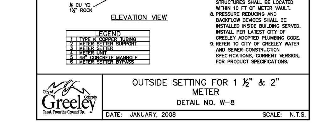
247 Page 243
248 Page 244
249 Page 245


250 Page 246
251 Page 247

252 Page 248
253 Page 249
254 Page 250

255 Page 251
256 Page 252
257 Page 253
258 Page 254
259 Page 255
260 Page 256
261 Page 257
262 Page 258
263 Page 259
264 Page 260
265 Page 261
266 Page 262
267 Page 263
268 Page 264
269 APPENDIX Description Page No. A1 A2 A3 A4 A5 A6 A7 A8 A9 E1 E2 E3 E4 E5 Introduction to Development Review Checklists Final Construction Plans Checklist Final Hydraulic Report Checklist for Potable Water and Sanitary Sewer Final Design Report Checklist for Non-Potable Irrigation Systems Verification Survey Checklist and Certification Cross Connection and Backflow Prevention Policy Compound Tap Exemption Policy for Irrigation of Multiple Outlots Policy Statements Governing the Sale of Potable Water and Sanitary Sewer Taps Policies Impacting Design and Construction Exclusive Water Easement Exclusive Sanitary Sewer Easement Exclusive Non-Potable Water Easement Exclusive Sanitary Sewer and Water Easement Temporary Construction Easement Crossing Approval Packet for All Water and Sewer Crossings APPENDIX Page 265
270 Page 266
271 A1 - INTRODUCTION TO DEVELOPMENT REVIEW CHECKLISTS A2 - Final Construction Plans Checklist A3 - Final Hydraulic Report Checklist for Potable Water and Sanitary Sewer A4 - Final Design Report Checklist for Non-Potable Irrigation Systems A5 - Verification Survey Checklist and Certification The Town of Hudson requires the submittals listed above on development projects. The checklists have been developed to assist in preparation of construction documents for potable water, sanitary sewer, and non-potable irrigation improvements. The checklists include items pertinent for the Town's review and reflect established professional engineering practice for preparation of the construction documents. Please note that all submittals required the preparation to be overseen, stamped, and signed by a Registered Professional Engineer, currently licensed in the State of Colorado. Items provided in the checklists are intended to provide guidance to meet the minimum requirements of the submittals listed. The items described in the checklists are not intended to be all inclusive for every project; therefore, additional work items may be appropriate. The submittals listed above shall be complete and self-supporting, including details and documents necessary for the construction of the proposed improvements. Submittals of incomplete documents will delay the development process. A1 - INTRODUCTION TO DEVELOPMENT REVIEW CHECKLISTS Page 267
272 Page 268
273 A2 - FINAL CONSTRUCTION PLANS CHECKLIST 1. GENERAL FOR ALL SHEETS: Sheets are 24" by 36", maximum size Legend describing line types, symbols, abbreviations, etc. Town acceptance signature blocks, as appropriate Stamped plans - checked, sealed, signed and dated by the Design Engineer Bar scale North arrow Key map Benchmarks Checked final construction plan requirements for other Town Departments 2. COVER SHEET: Project name and location Sheet index Vicinity map Legend Name/contact information of Owner, Developer, Design Engineer, Land Surveyor, Landscaper, Architect, etc. Town recognized project benchmarks and two (2) horizontal control points (northings and eastings) 3. NOTES SHEET: Project applicable water, sewer, and non-potable notes. See Section 13: GENERAL NOTE Project applicable general construction notes from other Town Departments 4. UTILITY PLAN: Proposed and existing streets and alleys with labeled names and right-of-way width Lot and block numbers Property lines Proposed and existing utilities on and within 100 feet of the project site Proposed and existing easements including name and width; Recording information for existing easements Storm drainage facilities Phasing boundaries for utilities and structures Proposed and existing water, sewer, and non-potable points of connection to existing systems Water, sewer, and non-potable appartenances - manholes, hydrants, valves, irrigation structures, services, etc. Labeled water, sewer, and non-potable pipe diameter, pipe material, and year of installation, if available Labeled utilities to be abandoned Adjacent property owner information Utility Co. and Ditch Co. signature lines Lots identified to have shallow sewer, if any 5. CONDUIT PLAN: All checklist items under Section 4: UTILITY PLAN are provided on the conduit plan Location shown for all conduits crossing right-of-way or easement Labeled conduit diameter Labeled number of conduits at a single crossing location Labeled depth of cover for conduit installation Labeled utility designated for each conduit Signature line for all Utility Companies having conduit sleeves crossing rights-of-way or easements The following note: All utility conduit crossings of potable water, sanitary sewer, and non-potable irrigation lines shall be encased in High Density Polyethylene (HDPE) Pipe, with a minimum Standard Dimension Ratio (SDR) 11 across the entire easement or right-of-way width. The encasement joint shall be butt fused. Flexible joints are not allowed. A2 - FINAL CONSTRUCTION PLANS CHECKLIST Page 269
274 6. CONSTRUCTION PLAN VIEW - WATER AND NON-POTABLE IRRIGATION: Minimum horizontal design scale of 1" = 50' Horizontal alignment of water line and all appurtenances Proposed and existing streets and alleys with labeled names and right-of-way width Lot and block numbers Property lines Proposed and existing easements including name and width; Recording info for existing easements All other proposed and existing utilities and facilities Phasing boundaries for utilities and structures Indicated proposed method of connection to existing system Mainline appurtenances shown and labeled - valves, fittings, hydrants, services, meters, thrust blocks, restrained pipe lengths, etc. Labeled water line pipe diameter, pipe material, and year of installation Match lines labeled with corresponding sheet number Size and location (by station) of services Key map North arrow Bar scale Pipe or street centerline stationing Stationing provided for all mainline appurtenances Horizontal location information provided for all mainline appurtenances (i.e. northings/eastings, station offset) 7. CONSTRUCTION PROFILE VIEW - WATER AND NON-POTABLE IRRIGATION: Minimum vertical design scale of 1" = 10' Vertical alignment of water line and all appurtenances All existing and proposed utility crossings shown and labeled including diameter Phasing boundaries Mainline appurtenances shown and labeled - valves, vertical deflections, water line lowerings, etc. Labeled clearance distance between profiled water line and all crossing utilities Labeled water line diameter, pipe material, pipe class, and length of pipe between fittings Match lines labeled with corresponding sheet number Stationing provided for all mainline appurtenances Labeled top of pipe elevations on proposed fittings, valves, and points of vertical deflection Labeled depth of cover between top of water line and finished grade Existing and proposed ground lines Phasing boundaries for water line, if any 8. CONSTRUCTION PLAN VIEW - SANITARY SEWER: Minimum horizontal design scale of 1" = 50' Horizontal alignment of sewer line and all appurtenances Proposed and existing streets and alleys with labeled names and right-of-way width Lot and block numbers Property lines Proposed and existing easements including name and width; Recording info for existing easements All other proposed and existing utilities and facilities Phasing boundaries for utilities and structures Indicated proposed method of connection to existing system Mainline appurtenances shown and labeled - manholes, services, etc. Labeled sewer line pipe diameter, pipe material, and year of installation (if available) Match lines labeled with corresponding sheet number Size and location (by station) of services Key map North arrow Bar scale A2 - FINAL CONSTRUCTION PLANS CHECKLIST Page 270
275 Pipe or street centerline stationing Stationing provided for all manholes Horizontal location information provided for all manholes (i.e. northings/eastings, station offset) Lots identified that have shallow sewer, if any 9. CONSTRUCTION PROFILE VIEW - SANITARY SEWER: Minimum vertical design scale of 1" = 10' Vertical alignment of sewer line and all appurtenances All existing and proposed utility crossings shown and labeled including diameter Phasing boundaries Mainline appurtenances shown and labeled - manholes, length of pipe between manholes, pipe slopes, manhole rim elevations, all mainline and service invert elevations, etc. Labeled clearance distance between profiled sewer line and all crossing utilities Labeled sewer line diameter and pipe material Match lines labeled with corresponding sheet number Stationing provided for all manholes Existing and proposed ground lines Phasing boundary, if any, for sewer line Identified lengths of shallow sewer main, if any 10. STANDARD DRAWING (DETAIL) SHEET(S): Project applicable, Town of Hudson Utilities Department Standard Drawings Project applicable Standard Drawings from other Town Departments Details of any critical connections, crossings, special fittings, project specific installation detail, etc. 11. LANDSCAPE PLANS: No plants with mature growth greater than 3 ft. in potable water/sanitary sewer/non-potable easements No shrubs within 5 ft. or trees within 10 ft. of meters, hydrants, manholes, mains, services or firelines Shown and labeled irrigation taps and meters, including size The following note: No plant material with mature growth greater than three (3) feet in height shall be planted within potable water, sanitary sewer, or non-potable irrigation easements. The following note: No shrubs shall be planted within five (5) feet or trees within ten (10) feet of potable and non-potable water meters, fire hydrants, sanitary sewer manholes, or potable water, sanitary sewer, or nonpotable irrigation mains and services. 12. PLAT: Labeled and dimensioned all proposed and existing potable water/sanitary sewer/non-potable easements Recording information for existing easements Lots identified that have shallow sewer 13. GENERAL NOTES: The following potable water, sanitary sewer, and non-potable irrigation general notes shall be put on Construction Drawings as applicable: All construction work to be accepted by the Town shall conform to the Town of Hudson Construction Specifications and Design Standards. All over lot grading in the right-of-way or easement shall be completed prior to installing potable water, sanitary sewer, or non-potable irrigation lines. Contractor shall verify all utility locations prior to construction. Call Utility Notification Center of Colorado at or dial 811 for utility locates 48 hours prior to any excavation work. A2 - FINAL CONSTRUCTION PLANS CHECKLIST Page 271
276 Maintain a minimum of ten (10) feet horizontal clear distance separation between potable water mains/services and sanitary sewer or non-potable irrigation mains/services. Potable water mains/services are to be located 18- inches minimum above the sanitary sewer or non-potable irrigation mains/services. If field conditions vary from those shown on these plans and the sanitary sewer or non-potable mains/services cannot be located below the water main or service, a clear vertical distance of eighteen (18) inches below cannot be maintained, or a minimum ten (10) foot horizontal separation cannot be achieved, the Town shall be contacted immediately to review the situation. In all instances where a water line lowering, potable or non-potable, is required due to unforeseen field conditions, a detailed drawing shall be provided to the Town for acceptance prior to performing the work. Where potable water, sanitary sewer, and non-potable irrigation lines are located in common utility easement areas, there shall be no other utilities located horizontally within ten (10) feet of either line except at approved crossings. Contractor shall notify the Town one (1) week prior to commencing work after Town accepted Construction Drawings have been distributed and a preconstruction meeting has been held with the Town. Contractor shall pothole all existing utilities to be crossed by potable water, sanitary sewer, or non-potable irrigation lines at least 24 hours prior to crossing to ensure 18" minimum clearance for open cut crossings and 36" minimum clearance for bored crossings. Horizontal and vertical location of crossed existing utilities shall be recorded on the As-Constructed Record Drawings. Should any variations before or during construction to the potable water distribution, sanitary sewer collection, or non-potable irrigation system designs be considered, notice must first be given to the Town to determine if it needs acceptance by the Town. If so, a new plan shall be drawn and submitted to the Town for acceptance by the Design Engineer 72 hours prior to construction. Final construction plans are valid for construction one (1) year from the date of Town signature acceptance. All potable water mains, services, and hydrant lines shall have a minimum cover of five (5) feet and a maximum cover of six (6) feet unless otherwise indicated on the accepted Construction Drawings. All non-potable water mains and services shall have a minimum cover of three and a half (3.5) feet and a maximum cover of six (6) feet unless otherwise indicated on the accepted Construction Drawings. All new water mains shall be bulkheaded and tested and approved prior to connection to the existing water system. Valves which pass testing for pressure and leakage at the time of installation and the testing was performed in the presence of the Town may be considered as a bulkhead. Verification Survey - Top of pipe elevations at all potable and non-potable water line valves, and sanitary sewer manhole inverts shall be surveyed and provided to the Town by the Design Engineer for acceptance prior to paving construction. The verification survey shall also provide sewer pipe slopes and length and proposed finished ground elevations at all valve boxes and manhole rim elevations. All utility conduit crossings of potable water, sanitary sewer and non-potable irrigation lines shall be encased in High Density Polyethylene (HDPE) pipe, with a minimum Standard Dimension Ratio (SDR) 11 across the entire easement or right-of-way width. The encasement joint shall be butt fused. Flexible joints are not allowed. Wet taps shall be drilled by the Town for a fee. Call the Town at least 48 hours in advance to pay fees and schedule tap. 14. SERVICE OR MAIN ABANDONEMENTS Refer to Appendix Section A9 - Policies Impacting Design and Construction for service and main abandonment procedures. Include notes on Construction Drawings, as appropriate, for project specific abandonment. A2 - FINAL CONSTRUCTION PLANS CHECKLIST Page 272
277 DEVELOPMENT/PROJECT NAME: LOCATION: SUBMITTED BY: FIRM: CONTACT: PHONE: SUBMITTED DATE: DATE APPROVED: 1. GENERAL: Each page of report consecutively numbered 2. REPORT FORMAT: Title Page Engineer Certification Sheet Table of Contents Project Description and Location References Water System Modeling Sewer System Modeling Supplemental Engineering Calculations Appendices 3. TITLE PAGE: Report title Project name and location A3 - FINAL HYDRAULIC REPORT CHECKLIST FOR POTABLE WATER AND SANITARY SEWER Name/contact information of Owner, Developer, Design Engineer, Land Surveyor, Landscaper, Architect, etc. Report preparation date 4. ENGINEER CERTIFICATION SHEET: Certification statement Checked, sealed, signed and dated by the Design Engineer 5. TABLE OF CONTENTS: Table of contents A3 - FINAL HYDRAULIC REPORT CHECKLIST FOR POTABLE WATER AND SANITARY SEWER Page 273
278 6. PROJECT DESCRIPTION AND LOCATION: Site vicinity map of project site Legal description of project site Total site acreage Proposed land uses and acreage of each use area Number of lots or buildings Explanation of project phasing, if any Identified location of potable water/sanitary sewer connections Pipe diameter, pipe material, and year of installation for connections REFERENCES AND APPENDICES: Referenced used design criteria, resources, modeling software, etc. Appended modeling results printouts, fire flow tests, tables/charts/equations, calculations 7. WATER SYSTEM MODELING: Project site pressure zone Calculations - estimated population, design flow, peaking factors, etc. Water demand assumptions Hydrant and fire sprinkler system, if any, flow requirements All required scenarios modeled Printouts of modeling results Conclusions - Confirm that design requirements are met, discussed oversizing, stated size of water lines required, phasing, etc. 8. SEWER SYSTEM MODELING: Calculations - estimated population, design flow, peaking factors, d/d, pipe flow velocity, infiltration, etc. Sewer sizing assumptions All required sewer sizing and capacity analyses evaluated Printouts of modeling results, if any Conclusions - Confirm that design requirements are met, discussed oversizing, stated size of sewer lines required, phasing, shallow sewer, impacts of upstream developments on the project, etc. 9. SUPPLEMENTAL ENGINEERING CALCULATIONS: Description of calculation and why it is included Calculations - pipe restrained length, soil loadings, traffic loadings, casing pipe wall thickness, and air/vacuum/air release valve sizing, etc. A3 - FINAL HYDRAULIC REPORT CHECKLIST FOR POTABLE WATER AND SANITARY SEWER Page 274
279 DEVELOPMENT/PROJECT NAME: LOCATION: SUBMITTED BY: FIRM: CONTACT: PHONE: SUBMITTED DATE: DATE APPROVED: 1. GENERAL: A4 - FINAL DESIGN REPORT CHECKLIST FOR NON-POTABLE IRRIGATION SYSTEMS Each page of report consecutively numbered 2. REPORT FORMAT: Title Page Engineer Certification Sheet Table of Contents Project Description and Location References Design Flow Pond Design Pump Station Design Discussion Items Non-Potable Irrigation System Modeling Appendices 3. TITLE PAGE: Report title Project name and location Name/contact information of Owner, Developer, Design Engineer, Land Surveyor, Landscaper, Architect, etc. Report preparation date 4. ENGINEER CERTIFICATION SHEET: Certification statement Checked, sealed, signed and dated by the Design Engineer TABLE OF CONTENT Table of Contents A4 - FINAL DESIGN REPORT CHECKLIST FOR NON-POTABLE IRRIGATION SYSTEMS Page 275
280 5. PROJECT DESCRIPTION AND LOCATION: Site map of project site Location of irrigation pond, pump station, discharge/fill lines, overflow works Explanation of project phasing, if any Identified location of existing irrigation main connections Pipe diameter, pipe material, and year of installation for connections 6. REFERENCES AND APPENDICES: References used design criteria, resources, modeling software, etc. Appended modeling results printouts, tables/charts/equations, calculations, requirements, parameters 7. DESIGN FLOW Irrigated acreage Application rates/watering requirements 8. POND DESIGN Required storage volume High and low operating elevations 9. PUMP STATION DESIGN Design Flow Pump type and number Motor horsepower System head curves Head computations Discharge pressure 10. DISCUSSION ITEMS Water sources Lining system Aeration system Pond shoreline protection Overflow works Pond design Power and electrical requirements Control and monitoring systems Building requirements 11. NON-POTABLE IRRIGATION SYSTEM MODELING Calculations Irrigation demand assumptions All required scenarios modeled Printouts of modeling results Conclusions - Confirm that design requirements are met A4 - FINAL DESIGN REPORT CHECKLIST FOR NON-POTABLE IRRIGATION SYSTEMS Page 276
281 DEVELOPMENT/PROJECT NAME: LOCATION: SUBMITTED BY: FIRM: CONTACT: PHONE: SUBMITTED DATE: DATE APPROVED: 1. GENERAL: A5 - VERIFICATION SURVEY CHECKLIST AND CERTIFICATION Prepared for easy modification and transition to As-Constructed Drawings Surveyed information obtained by a Land Surveyor Surveyed information shown clouded or heavier line weight Original information lined through Survey drawing checked by Design Engineer 2. SURVEYED INFORMATION: Horizontal information - utilities, manholes, distances between manholes, valves, hydrants, etc. Vertical information - utilities, manhole invert elevations, top of pipe elevation at valves All top of nut valve elevations converted to top of pipe elevation Proposed information - manhole rims, ground elevations 3. VERIFICATION CERTIFICATION: I,, HEREBY STATE THAT I HAVE REVIEWED THE VERIFICATION SURVEY ELEVATIONS AND HORIZONTAL LOCATIONS PROVIDED FOR - (NAME OF DEVELOPMENT) AND CERTIFY THAT ACCORDING TO THE INFORMATION PROVIDED, THE CONSTRUCTED POTABLE WATER, SANITARY SEWER, OR NON-POTABLE IRRIGATION LINES ARE IN COMPLIANCE WITH TOWN OF HUDSON APPROVED CONSTRUCTION DRAWINGS AND STANDARDS AND WILL FUNCTION AS DESIGNED. Registered Professional Engineer (Affix Seal) A5 - VERIFICATION SURVEY CHECKLIST AND CERTIFICATION Page 277
282 Page 278
283 A6 - CROSS CONNECTION AND BACKFLOW PREVENTION POLICY The Town uses the Colorado Cross Connection Control Manual (CCCCM), latest edition, for backflow prevention assembly requirements, in accordance with the regulations of the Environmental Protection Agency (EPA), Safe Drinking Water Act, Colorado Primary Drinking Water Regulations (CPDWR), and the currently adopted Plumbing Code and Town of Hudson Code, Section through Section , Cross-Connection Control Program. assemblies protect the Town of Hudson's treated water supply from hazards that originate from plumbing connections that may impair or alter the treated water. The proper backflow assembly to install is critical, and shall be selected on the degree of hazard introduced by the plumbing connection that presents a risk to the treated water supply. The following hazard conditions could present a risk to the treated water supply: 1. High Hazard - Any condition, device, or practice that may introduce waterborne disease organisms or chemical, physical, or radioactive substances to the treated water supply and present a risk to public health. 2. Low Hazard - Any condition, device, or practice that may cause an aesthetic nuisance such as objectionable taste, color, or odor to be introduced into the treated water supply. The following table presents the Utilities Department standards for selection of appropriate backflow prevention assemblies: Type of Establishment - Normal single family dwelling; 1 to 2-story dwellings up to 4 units with standard fixtures; no additional hard-plumbed connections; no other identified health hazards. - Single family or 1 to 2-story multi-family 1 dwellings with standard fixtures; no additional hard-plumbed connections; no other identified health hazards; have a water-only fire sprinkler system. - 5 to 10 unit dwellings with 1-1/2" water taps 2 and standard fixtures; no additional hard-plumbed connections; no other identified health hazards. - All institutional, commercial, or industrial establishments. - Multi-family dwellings with 3-stories or more. - Multi-family dwellings with 11 units or more. - Multi-family dwellings with 5 to 10 units and larger than 1-1/2" taps. - Any type of establishment, including single family, with connections that present a risk to the treated water supply. Such connections include, but are not limited to, boiler systems, solar panels with circulated water or chemicals, hard-plumbed hot tubs/pools, evaporative coolers, any type of Minimum Required Backflow Assembly irrigation system 3, and fire sprinkler systems with chemicals 4. 1 Multi-family also includes multi-unit. 2 The tap size criteria are utilized as the basis for determining degree of hazard because the water tap size corresponds to the type and size of establishment or dwelling. 3 Depending upon the system design, irrigation systems shall have one of the following backflow assemblies: 1) air gap, 2) Atmospheric Vacuum Breaker (AVB), 3) Pressure Vacuum Breaker (PVB), or 4) Reduced Pressure Principle (RP). 4 Backflow prevention assemblies for commercial fire sprinkler systems shall include a Double Check Detector Assembly (DCDA) or Reduced Pressure Principle Detector Assembly (RPDA) as appropriate; residential fire sprinkler taps that are two- inch (2") in diameter or less are not required to install a detector assembly. None Detector Check (DC) Reduced Pressure Principle (RP) A6 - CROSS CONNECTION AND BACKFLOW PREVENTION POLICY Page 279
284 Backflow prevention assemblies are subject to the following requirements: 1. Backflow prevention assemblies shall be in conformance with and installed according to the CCCCM, latest edition, and these Criteria, installed and tested prior to Certificate of Occupancy, and re-tested every year thereafter. 2. All backflow prevention assembly models shall carry the American Society of Sanitary Engineering (ASSE) or the University of Southern California Foundation for Cross Connection Control and Hydraulic Research (USCFCCC & HR) approval seal. 3. All backflow prevention assemblies shall be reviewed and accepted by the Town of Hudson Utilities Department prior to installation. Product information sheets for each assembly shall be submitted to the Utilities Department for review and acceptance a minimum of one (1) week prior to scheduled installation. The submittal shall state the method of assembly installation (horizontal or vertical) and the proposed use of the water in the building. 4. Fire sprinkler line backflow prevention assemblies shall be located inside the building for which the fire sprinkler line services. In instances where locating the assembly in the building is not feasible, the assembly may be located outside provided it is protected from freezing. Pit installations shall be designed by a Professional Engineer experienced in fire protection systems. The pit design plans shall be reviewed and accepted by the Union Colony Fire Rescue Authority and Town of Hudson Building Inspection Division. 5. Where a routine annual inspection of the plumbing system is not performed on multi-family and commercial potable water services and fire sprinkler lines or in ANY case where a cross connection potential exists, all service connections inside the building shall be fitted with an approved backflow prevention assembly. 6. The Town, as the responsible water purveyor, reserves the right to make all final decisions regarding interpretations of the CCCCM. If any conflict arises between the CCCCM and the Town requirements, the Town requirements shall prevail. A6 - CROSS CONNECTION AND BACKFLOW PREVENTION POLICY Page 280
285 A7 - COMPOUND TAP EXEMPTION POLICY FOR IRRIGATION OF MULTIPLE OUTLOTS An exemption for a compound tap for the irrigation of multiple outlots within a subdivision may be allowed under the following conditions: 1. All outlots are owned by the same owner or a property-owners' association, and there is little chance of the properties being sold off individually. If outlots are sold off at some future time, each property owner must acquire a separate water tap at that time. Costs of the new taps will be spread among all lot owners. There will be no refund for Plant Investment Fees (PIFs) previously paid for a tap that now may be oversized. 2. A permanent arrangement for One-Call location of the irrigation lines must be provided that meets all requirements of the Colorado One-Call State Law (Senate Bill ). The existing law requires that all underground facility owners be registered with the Colorado Notification Association. 3. The property owner must obtain a revocable permit(s) from the Town of Hudson Public Works Department for use of the public right-of-way. Revocable permits are approved by Town Council and shall include: a. An identified permit holder. b. Accepted Construction Drawings on file with the Town. c. Owner recognition that if the permit is revoked, additional water taps must be purchased for each outlot. 4. PIFs and any additional raw water must be paid for all irrigation outlots. 5. The property owner acknowledges that pressure and water delivery may suffer when a single tap is used to irrigate multiple lots. 6. "IRR" shall be stamped in the concrete on the curb on both sides of the street where the irrigation conduit crosses the right-of-way or easement. A7 - COMPOUND TAP EXEMPTION POLICY FOR IRRIGATION OF MULTIPLE OUTLOTS Page 281
286 Page 282
287 A8 - POLICY STATEMENTS GOVERNING THE SALE OF POTABLE WATER AND SANITARY SEWER TAPS 1. Potable water and sanitary sewer taps become part of the property they serve when installed; therefore, taps may not be bought or sold among property owners nor transferred to another property. 2. Plant investment fees (PIFs) can only be collected for specific lots; taps may not be purchased without a location or assigned address. 3. PIFs should not be collected unless a tap can be physically installed. Taps may only be purchased for lots which are adjacent to potable water and sanitary sewer mains. Main extensions may be required for which the Developer/Owner must provide Town accepted engineered Construction Drawings. 4. Taps previously sold, but not installed, may only be installed to the property of the purchaser, and become part of the property, should it be sold later. Taps may not be transferred and installed on the property of others 5. Reimbursement may be made for taps previously purchased but not yet installed. Reimbursement will be for the amount paid at the time of purchase, including any labor and materials fees paid. Town ordinance prohibits refunds for any taps already installed; however, credit may be applied toward the purchase of a larger tap for the same property. If credit for an existing tap is applied toward the purchase of a new tap, the existing tap must be abandoned as current policy stipulates. 6. Taps sold for multi-family structure must meet the Multiple Living Unit Structure (MLUS) guidelines; a condominium declaration or a similar binding agreement must be submitted to the Utilities Department by the Owner(s) of such structures. Specifically, the bill paying entity must be identified within the document. 7. Each residential structure (building) as defined under the MLUS policy must have a separate water tap, meter, and sewer tap. We don on install individual meters for customers who receive water service from a master water tap. 8. Purchasers of water taps must comply with the maximum number of units as state in the Water and Sewer Board rate resolution. For example, the maximum number of units allowed on a one-inch (1") water tap is four (4). PIFs are not calculated for multi-family units on a per unit basis. 9. A 5/8-inch (5/8") water tap is treated as a 3/4-inch (3/4") water tap for fee credit when a customer applies for a larger tap. Abandonment of the 5/8-inch (5/8") water tap is required at the point of connection on the main. The Town charges a fee to drill new taps on the main, but does not charge a fee to abandon taps. The installation and abandonment of taps shall be coordinated with the Town of Hudson Water Distribution Division. 10. The 5/8-inch (5/8") tap was the minimum water tap size prior to the ¾-inch (3/4") tap becoming the minimum size. Therefore, a 5/8-inch (5/8") water tap shall be treated like a ¾-inch (3/4") unless a property owner proposes to serve more than one (1) dwelling unit with a 5/8-inch (5/8") tap. In this situation, no additional PIF would be due to serve two (2) units; however, the Town charges a drilling fee (Labor and Materials) to install a new ¾-inch (3/4") tap on the main. The property owner must abandon the 5/8-inch (5/8") water at his/her own expense. 11. Raw water is paid by everyone unless excepted by Town ordinance. Exceptions are rare; however, those exception most often applicable are as follows: a. Residential Users: Property which was subdivided and plats accepted by the Hudson Planning Commission prior to 1961 are excepted from providing raw water unless the property is further subdivided and an additional tap or taps are requested. b. Non-residential Users: Property excepted by ordinances will still be subject to the base annual allotment which is based on the size of the water tap requested. A raw water surcharge is assessed on all water used above the base annual allotment each year. A8 - POLICY STATEMENTS GOVERNING THE SALE OF POTABLE WATER AND SANITARY SEWER TAPS Page 283
288 Page 284
289 A9 - POLICIES IMPACTING DESIGN AND CONSTRUCTION Water Services 1. If a stubbed tap is the wrong size, it must be changed at the main either by redrilling, downsizing, or abandoning and drilling a new tap of the appropriate diameter. The Town does not permit downsizing of potable water services at the meter. Potable water services must be the same diameter from the main, through the meter, to five (5) feet beyond the meter. Listed below are acceptable procedures for acquiring the correct water service diameter: a. Redrilling. This procedure is applicable for taps that need to be upsized to a larger diameter. The corporation stop from the existing tap shall be removed and a new tap of the appropriate larger diameter shall be drilled in the same hole where the existing tap was located. b. Downsizing. This procedure is applicable for taps that need to be downsized to a smaller diameter. The corporation stop from the existing tap shall be removed and a bushing of the appropriate outside and inside diameters shall be installed in the same hole where the prior tap was located. The smaller service corporation stop shall be threaded into the bushing. c. Abandonment and New Drill. This procedure is applicable for taps that need to be upsized to a larger diameter or downsized to a smaller diameter. The existing tap shall be abandoned per approved abandonment procedures (see below). A new tap of the correct diameter shall be drilled a minimum of two (2) feet from the abandoned tap. 2. Town maintenance responsibility for water services shall be the water main, corporation stop, service piping up to the curbstop, and the tube nut on the street side of the curb stop. Sanitary Sewer Services 1. Per the Home Rule Charter for the County of Weld Colorado, Sec , latest revision, a property requiring sanitary sewer service must connect to the sanitary sewer system if the structure to be served is within four-hundred (400) feet of a sewer connections. 2. Per the Town of Hudson Charter and Code, Title 14: Public Services, Section , a property requiring sanitary sewer service must connect to the sanitary sewer system if the property on which the structure to be serviced is located within two-hundred (200) feet of a sewer connection. 3. Sanitary sewer connections in either case shall be made at the property owner's expense. 4. Town maintenance responsibility for sanitary sewer service ends at the main. The property owner is responsible for sewer service maintenance beyond the main connection including the service tapping saddle. Non-potable Irrigation 1. Non-potable irrigation systems are required when the combined total open space/common space turf area for a development is twenty (20) acres or more, unless otherwise indicated by the Town. 2. In instances where irrigation services are allowed to cross or be located in the public right-of-way, the Developer must obtain a revocable permit from the Town of Hudson Public Works Department for use of the public right-of-way. 3. A permanent arrangement for the One-Call location of the irrigation lines must be provided that meets all requirements of the Colorado One-Call State Law. The existing law requires that all underground facility owners be registered with the Colorado Notification Association. The revocable permit holder must be the owner registered with the Colorado Notification Association. 4. If the permit to use the public right-of-way is revoked, additional water taps must be purchased for each lot. Fire Sprinkler Services 1. There is no raw water dedication or plant investment fee requirements for fire sprinkler lines. 2. Town maintenance responsibility for fire sprinkler lines ends at the mainline gate valve. The property owner is responsible for fire sprinkler line maintenance beyond the mainline gate valve. A9 - POLICIES IMPACTING DESIGN AND CONSTRUCTION Page 285
290 Utility Crossing If a utility must cross an existing potable water distribution, sanitary sewer collection, or non-potable irrigation main, within a development that has entered into the two (2) year warranty period, a utility crossing approval shall be required from the Utilities Department. Refer to Appendix Section Crossing Approval Packet for utility crossing requirements. Easements 1. For potable water distribution, sanitary sewer collection, or non-potable irrigation lines located in easements, future repair of paving, landscaping, or other improved surfaces subsequent to the repair of a line shall be the responsibility of the property owner/home owners' association. The Town will backfill the trench to the surface but not rebuild any surface improvements or replace landscaping. 2. The Town shall have the exclusive utility use of dedicated exclusive easements except for right angled utility crossings. Crossing utilities shall be granted the right to install, lay, construct, relocate, change the size of, replace, repair, inspect, maintain, remove, and operate underground utility and all appurtenances thereto subject to the terms of said Town exclusive easements. The Utilities Department shall review for acceptance all utility crossing methods and work within the exclusive easements. Underdrains 1. The Developer shall accept all liability and responsibility for underdrain installation. 2. Underdrain systems shall be maintained by the Home Owners' or Property Owners' Association. Service or Main Abandonment Procedures 1. Water Service and Main Abandonments a. ¾" to 2" direct taps on DIP or Cast Iron Excavate the water main, turn off the corporation stop, cut out a 1 ft. section of the service line, install a plugged tube nut at the corporation stop and crimp the existing water service line. Remove the curb stop box at the property line. b. ¾" to 2" taps on C-900 PVC Excavate the water main, remove the corporation stop, cut out a 1 ft. section of the service line, plug the tapping saddle and crimp the existing water service line. Remove the curb stop box at the property line. c. 4" and larger Excavate the water main, remove the gate valve, and cap or plug the tee. Contractor is responsible for notifying affected customers 24 hours prior to water shut down. Only Town of Hudson Water Department personnel shall operate the main line valves. 2. Sanitary Sewer Service and Main Abandonments a. Sanitary sewer main and service lines shall be abandoned at the property line. b. Excavate the sanitary sewer service or main, remove a minimum 2 ft. section of pipe, install a wing-nut plug (or approved equivalent), and pour a concrete cap over the end of pipe. c. Abandoned sanitary sewer mains and service lines that discharge into a manhole shall be filled with sandbags and sealed inside the manhole with non-shrink grout A9 - POLICIES IMPACTING DESIGN AND CONSTRUCTION Page 286
291 EXCLUSIVE WATER EASEMENT KNOW ALL MEN BY THESE PRESENTS, that, whose address is, hereinafter referred to as "Grantor", for and in consideration of Ten and no/100 dollars ($10.00) and other valuable consideration, the receipt and sufficiency of which is hereby acknowledged, hereby grants and conveys to the Town of Hudson, a Municipal corporation, whose address is 50 South Beech, Hudson, CO 80642, hereinafter referred to as "Grantee", a permanent exclusive water easement. Below is the description of the exclusive easement. SEE ATTACHED LEGAL DESCRIPTION AND DRAWING The permanent exclusive water easement hereby granted shall entitle the Grantee, its successors and assigns, to install, lay, construct, relocate, change the size of, replace, repair, inspect, maintain, remove, and operate an underground pipeline and all appurtenances thereto. The permanent exclusive water easement also shall permit uses clearly incidental to those specified and shall include the right of ingress and egress over and across the Grantor's property to the extent reasonably necessary to exercise and accomplish the operational purposes and the right to clear and keep cleared all trees and other obstructions as may be necessary. The Grantor shall have the right to make use of the surface overlying the exclusive water easement granted by this instrument so long as such use does not interfere with the exercise by the Grantee of the rights granted and conveyed by this instrument. No permanent structures or detention ponds are to be built within this easement. Grantor shall not install berms, fences, or plantings, which exceed three feet in height when mature, in the easement. In no event, shall the Grantor make claim against the Grantee for damages to any improvements or fixtures hereafter installed by the Grantor within the area of the permanent exclusive water easement. hereto. This Grant shall be binding upon the heirs, executors, administrators, successors and assigns of the parties IN THE WITNESS, WHEREOF the Grantors have hereunto set their hands and seals on this day of 20. Grantor: STATE OF COLORADO ) ) ss. COUNTY OF WELD ) Grantor: Acknowledged before me on this day of 20, by. WITNESS MY HAND AND MY SEAL. MY COMMISSION EXPIRES (Notary Public) Accepted by Town of Hudson Utilities Department: Signature: Title: Date: E1 - Town of Hudson W&S ROW No. Form-2007 Exclusive Water Easement Page 287
292 Page 288
293 EXCLUSIVE SANITARY SEWER EASEMENT KNOW ALL MEN BY THESE PRESENTS, that, whose address is, hereinafter referred to as "Grantor", for and in consideration of Ten and no/100 dollars ($10.00) and other valuable consideration, the receipt and sufficiency of which is hereby acknowledged, hereby grants and conveys to the Town of Hudson, a Municipal corporation, whose address is 50 South Beech Street, Hudson, CO 80642, hereinafter referred to as "Grantee", a permanent exclusive sanitary sewer easement. Below is the description of the exclusive easement. SEE ATTACHED LEGAL DESCRIPTION AND DRAWING The permanent exclusive sanitary sewer easement hereby granted shall entitle the Grantee, its successors and assigns, to install, lay, construct, relocate, change the size of, replace, repair, inspect, maintain, remove, and operate an underground pipeline and all appurtenances thereto. The permanent exclusive sanitary sewer easement also shall permit uses clearly incidental to those specified and shall include the right of ingress and egress over and across the Grantor's property to the extent reasonably necessary to exercise and accomplish the operational purposes and the right to clear and keep cleared all trees and other obstructions as may be necessary. The Grantor shall have the right to make use of the surface overlying the exclusive sanitary sewer easement granted by this instrument so long as such use does not interfere with the exercise by the Grantee of the rights granted and conveyed by this instrument. No permanent structures or detention ponds are to be built within this easement. Grantor shall not install berms, fences, or plantings, which exceed three feet in height when mature, in the easement. In no event shall the Grantor make claim against the Grantee for damages to any improvements or fixtures hereafter installed by the Grantor within the area of the permanent exclusive sanitary sewer easement. hereto. This Grant shall be binding upon the heirs, executors, administrators, successors and assigns of the parties IN THE WITNESS WHEREOF the Grantor has hereunto set their hand and seal on this day of 20. STATE OF COLORADO ) ) ss. COUNTY OF WELD ) Grantor: Grantor: Acknowledged before me on this day of 20. by WITNESS MY HAND AND MY SEAL. MY COMMISSION EXPIRES (Notary Public) Accepted by Town of Hudson Utilities Department: Signature: Title: Date: E2 - Town of Hudson W&S ROW No. Form-2007 Exclusive Sanitary Sewer Easement Page 289
294 Page 290
295 EXCLUSIVE NON-POTABLE WATER EASEMENT KNOW ALL MEN BY THESE PRESENTS, that, whose address is, hereinafter referred to as "Grantor", for and in consideration of Ten and no/100 dollars ($10.00) and other valuable consideration, the receipt and sufficiency of which is hereby acknowledged, hereby grants and conveys to the Town of Hudson, a Municipal corporation, whose address is 50 South Beech Street, Hudson, CO 80642, hereinafter referred to as "Grantee", a permanent exclusive non-potable water easement. Below is the description of the exclusive easement. SEE ATTACHED LEGAL DESCRIPTION AND DRAWING The permanent exclusive non-potable water easement hereby granted shall entitle the Grantee, its successors and assigns, to install, lay, construct, relocate, change the size of, replace, repair, inspect, maintain, remove, and operate an underground utility and all appurtenances thereto. The permanent exclusive non-potable water easement also shall permit uses clearly incidental to those specified and shall include the right of ingress and egress over and across the Grantor's property to the extent reasonably necessary to exercise and accomplish the operational purposes and the right to clear and keep cleared all trees and other obstructions as may be necessary. The Grantor shall have the right to make use of the surface overlying the exclusive non-potable water easement granted by this instrument so long as such use does not interfere with the exercise by the Grantee of the rights granted and conveyed by this instrument. No permanent structures or detention ponds are to be built within this easement. Grantor shall not install berms, fences, or plantings, which exceed three feet in height when mature, in the easement. In no event shall the Grantor make claim against the Grantee for damages to any improvements or fixtures hereafter installed by the Grantor within the area of the permanent exclusive non-potable water easement. hereto. This Grant shall be binding upon the heirs, executors, administrators, successors and assigns of the parties IN THE WITNESS WHEREOF the Grantor has hereunto set their hand and seal on this day of 20. Grantor: Grantor: STATE OF COLORADO ) ) ss. COUNTY OF WELD ) Acknowledged before me on this day of 20, by WITNESS MY HAND AND MY SEAL. MY COMMISSION EXPIRES: Notary Public) Accepted by Town of Hudson Utilities Department: Signature: Title: Date: E3 - Town of Hudson W&S ROW No. Form Exclusive Non-Potable Water Easement Page 291
296 Page 292
297 EXCLUSIVE SANITARY SEWER AND WATER EASEMENT KNOW ALL MEN BY THESE PRESENTS, that, whose address is, hereinafter referred to as "Grantor", for and in consideration of Ten and no/100 dollars ($10.00) and other valuable consideration, the receipt and sufficiency of which is hereby acknowledged, hereby grants and conveys to the Town of Hudson, a Municipal corporation, whose address is 50 South Beech Street, Hudson CO 80642, hereinafter referred to as "Grantee", a permanent exclusive sanitary sewer and water easement. Below is the description of the exclusive easement. SEE ATTACHED LEGAL DESCRIPTION AND DRAWING The permanent exclusive sanitary sewer and water easement hereby granted shall entitle the Grantee, its successors and assigns, to install, lay, construct, relocate, change the size of, replace, repair, inspect, maintain, remove, and operate one or more underground sanitary sewer/water utility pipeline(s) and all appurtenances thereto. The permanent exclusive sanitary sewer and water easement also shall permit uses clearly incidental to those specified and shall include the right of ingress and egress over and across the Grantor's property to the extent reasonably necessary to exercise and accomplish the utility purposes and the right to clear and keep cleared all trees and other obstructions as may be necessary. The Grantor shall have the right to make use of the surface overlying the exclusive sanitary sewer and water easement granted by this instrument so long as such use does not interfere with the exercise by the Grantee of the rights granted and conveyed by this instrument. No permanent structures or detention ponds are to be built within this easement. Grantor shall not install berms, fences, or plantings, which exceed three feet in height when mature, in the easement. In no event shall the Grantor make claim against the Grantee for damages to any improvements or fixtures hereafter installed by the Grantor within the area of the permanent sanitary sewer and water easement. hereto. This Grant shall be binding upon the heirs, executors, administrators, successors and assigns of the parties IN THE WITNESS WHEREOF the Grantor has hereunto set their hand and seal on this day of 20. Grantor: STATE OF COLORADO ) ) ss. COUNTY OF WELD ) Grantor: Acknowledged before me on this day of 20, by. WITNESS MY HAND AND MY SEAL. MY COMMISSION EXPIRES (Notary Public) Accepted by Town of Hudson Utilities Department: Signature: Title: Date: E4 - Town of Hudson W&S ROW No. Form-2007 Exclusive Sanitary Sewer & Water Easement Page 293
298 Page 294
299 TEMPORARY CONSTRUCTION EASEMENT This Temporary Construction Easement is made this day of,, by and between,, whose address is, ("GRANTOR"), and the Town of Hudson, a Municipal corporation, whose address is 50 South Beech Street, Hudson CO ("GRANTEE"). GRANTOR, for and in consideration of the sum of Ten and no/100 dollars ($10.00) and other valuable consideration paid by the GRANTEE to the GRANTOR, the receipt and sufficiency of which is hereby acknowledged, has granted, bargained, sold and conveyed, and by this Temporary Construction Easement does grant, bargain, sell, convey and confirm to the GRANTEE, its successors and assigns forever, a temporary nonexclusive easement on and under the property as per the Legal Description and Drawing attached hereto and incorporated herein by this reference, located in Weld County, Colorado ("Property"); for the purposes of: 1. Surveying, locating, installing, and constructing a buried pipeline on lands adjacent to the Property, in whole or in part; 2. Cutting and clearing trees, brush, debris, and other obstructions on the Property that might interfere with GRANTEE'S activities on the Property; and 3. Access for purposes of surveying, locating, installing, and constructing a buried pipeline across property owned by the GRANTOR that is contiguous to the Property with the GRANTOR'S consent, which consent shall not be unreasonably withheld. Temporary Construction Easement shall begin on the date set out above and shall terminate upon completion of construction or on, whichever occurs first. During the term of this Temporary Construction Easement GRANTOR shall not place, erect, install or permit any above or below ground building, structure, or other obstruction on the Property that may interfere with the GRANTEE'S activities on the Property hereunder. The GRANTEE shall: 1. Insofar as practicable, restore the surface of the ground to its condition prior to GRANTEE'S activities on the Property; 2. Insofar as practicable, restore fences, drain tile, irrigation systems, landscaping, private roads and other improvements, to the conditions existing prior to GRANTEE'S activities on the Property; and 3. Pay the GRANTOR the actual damages to growing crops, livestock, and other items caused by GRANTEE'S activities on the Property. E5 - Town of Hudson W&S ROW No. Form Temporary Construction Easement Page 295
300 GRANTOR warrants and will forever defend the title to the Property. Grantor: STATE OF COLORADO ) ) ss. COUNTY OF WELD ) Acknowledged before me on this day of 20, by. WITNESS MY HAND AND MY SEAL. MY COMMISSION EXPIRES (Notary Public) Accepted by Town of Hudson Utilities Department: Signature: Title: Date: E5 - Town of Hudson W&S ROW No. Form Temporary Construction Easement Page 296
301 TOWN OF HUDSON UTILITIES DEPARTMENT CROSSING APPROVAL PACKET FOR ALL WATER & SEWER CROSSINGS Contact: Town of Hudson 50 South Beech Street Hudson CO Ph: Page 297
302 Page 298
303 CROSSING APPROVAL PROCEDURES TOWN OF HUDSON UTILITIES DEPARTMENT 50 South Beech Street, Hudson CO APPROVAL PROCEDURES: Please note the Crossing Approval issued by Utilities applies ONLY to Water & Sewer facilities. Contractor/Owner is responsible for identifying and obtaining any and all permits and/or approvals required from any public agency or private property owner. Submit for approval a minimum of 2 weeks prior to construction. Pot Hole of Existing Pipelines: When a new project identifies that a Town of Hudson Water& Sewer Pipeline is within the project area, the water and sewer pipelines must be pot-holed to determine location and depth of existing pipelines. It is the responsibility of the Contractor/Facility Owner to obtain appropriate approval for doing the pot-hole of the water and sewer pipelines. This is done by submitting a location map showing where the Contractor/Facility Owner will be crossing the Town of Hudson water and/or sewer facilities. When in public right of way, the appropriate permit must be obtained from the agency with jurisdiction for the road. Utilities Department will sign off or issue an "OK to Pothole" as requested by the Public Works Department. When on private property within a Town Easement area, the approval or right of entry must be obtained from the property owner. The Utilities Department DOES NOT issue pot-hole permits or private property approvals. Crossing Approval Application: Complete all pertinent information. Plan and Profile Drawing Required (After Potholing Completed): (Attached is Minimal Design Standards and sample Plan & Profile Drawing): A. Plans to show location information and placement of facility being installed, incorporating location and depth of pipelines identified by pot-hole. B. Plans to show how facility will be installed (bore, trench, other). C. Plans to show type, size, etc. of facilities being installed, including crossing tape, marker posts, etc. D. Town of Hudson water, sewer, and non-potable pipelines to be identified, if located in Town of Hudson Water & Sewer easement the width shall be shown on drawing. E. The actual distance of clearance, both vertical and horizontal, to be shown from new facility to existing water and sewer pipelines. Submit Completed Application and Plan/Profile Drawing: Submit to Water & Sewer a minimum of two weeks prior to proposed construction date. Plan Check Review by Utilities: Plan check and review of application to be completed by Water & Sewer, which requires confirmation of easement width, approval of proposed clearance and installation. Additional information and/or drawing revisions will be requested if necessary. Crossing Approval Issued: When all information is received and plan & profile drawing approved, Town of Hudson Utilities will (1) issue Original/Signed Crossing Approval Application; (2) provide any Approval Conditions that apply and (3) Stamp, Sign & Date approved Plan/Profile Drawing. The Original of the Approval and the Plan & Profile Drawing will be furnished to Contractor/Owner (these must be on-site during construction), with a copy available for Water & Sewer Inspector. Contractor/Owner is responsible for identifying and obtaining any and all permits and/or approvals required from any public agency or private property owner. Inspection Notice: Contractor/Owner to arrange for Town of Hudson Utilities inspector prior to any construction activities, including potholing, within the Town of Hudson s Water & Sewer Easements and/or existing water, sewer, or non-potable pipelines in a public street Right of Way. Page 299
304 Page 300
305 TOWN OF HUDSON UTILITIES DEPARTMENT MINIMAL STANDARDS FOR UTILITIES CROSSING OR PARALLELING EXISTING WATER AND SEWER FACILITIES The following requirements are standard and pertain to every utility that intends to cross or parallel our existing potable/non-potable water or sewer lines. These are minimal standards that may be changed upon plan review due to field conditions. Installation plans must be submitted to the Utilities Department, 50 South Beech Street, Hudson CO for review and approval a minimum of two weeks prior to the beginning of construction. MINIMAL REQUIREMENTS: Parallel Installation: Parallel installations shall maintain a minimum of 5 feet clear horizontal separation in a public rightof-way. Parallel installations shall not be allowed in exclusive water and sewer easements. Perpendicular Crossings Installation: For bored crossings, there shall be a minimum of 2 feet clear separation above or 3 feet clear separation below existing water or sewer mains or services. When reaming, you must allow for the outside diameter of the reamer plus the applicable 2 or 3 feet distance. For open cut crossings, a minimum of 18" clear separation above or 3 feet clear separation below existing water or sewer mains or services. (NOTE: The exact clearance distance, not the minimum, must be shown on the profile.) All crossings shall be contained in an encasement pipe that can be: DIP Cl 51, or Steel with a minimum of.25 wall, or SDR 11HDPE polyethylene piping, or Arnco Corporation s "Smooth-Cor". (NOTE: Any variation from above conduits must be reviewed and approved by Water & Sewer) The encasement piping shall span a minimum of 10 feet on both sides of an existing water or sewer main. Any crossing that spans an exclusive water or sewer easement shall span the entire easement with the casing. All crossings must be at a 90-degree angle to the water or sewer main. Research Required Potholing (check with Public Works for specifications and permit) is required to verify the depth of the water or sewer line and must be witnessed by a representative of the Water & Sewer Department. This acquired data must be shown on a profile view on the proposed crossing plan. To allow for approval review, the plan, along with a completed crossing approval application, must be submitted a minimum of two weeks in advance of construction. A Water & Sewer representative shall verify all crossings. To schedule this service, call forty-eight hours prior to needing the representative. Page 301
306 Page 302
307 Sample Crossing Approval Plan and Profile in Public ROW Page 303

308 Sample Crossing Approval Plan and Profile in Private Easement Page 304