Characterization and Testing of Fiber Reinforced Concrete (American Standards)
|
|
|
- Jack Pearson
- 5 years ago
- Views:
Transcription


1 Workshop on FIBER REINFORCED CONCRETE (FRC): MATERIALS, APPLICATIONS AND DESIGN ASPECTS UNIVERSITY OF SHARJAH, UNITED ARAB EMIRATES APRIL 2018 Characterization and Testing of Fiber Reinforced Concrete (American Standards) Prof. Salah Altoubat Department of Civil & Environmental Engineering SCMASS Research Group College of Engineering University of Sharjah April, 23, 2018


2 Introduction Fibers mixed into concrete can provide an alternative means of reinforcement to partially or fully replace steel bars or welded wire mesh in certain applications. Fibers can contribute to the improved performance of concrete members in two different ways: by resisting tensile stresses and therefore playing a structural role, or by controlling crack development and therefore improving the quality of concrete. When fibers are intended to contribute to the structural performance of an element or structure, the FRC needs to be designed accordingly and the fibers contribution to the load-bearing capacity needs to be properly assessed and justified. Fibers intersect cracks when they initiate. This allows for a uniform distribution of the stresses that develop and slow down crack propagation
3 Advantages of using fibers Economic Significant decrease in production cycle time Reduced labor costs Reduction in breakage and repair costs Reduce potential for corrosion (only polymeric) Technical Crack - reduction Increased ductility and flexural toughness Good impact resistance Prevention of concrete spalling Provide Residual strength

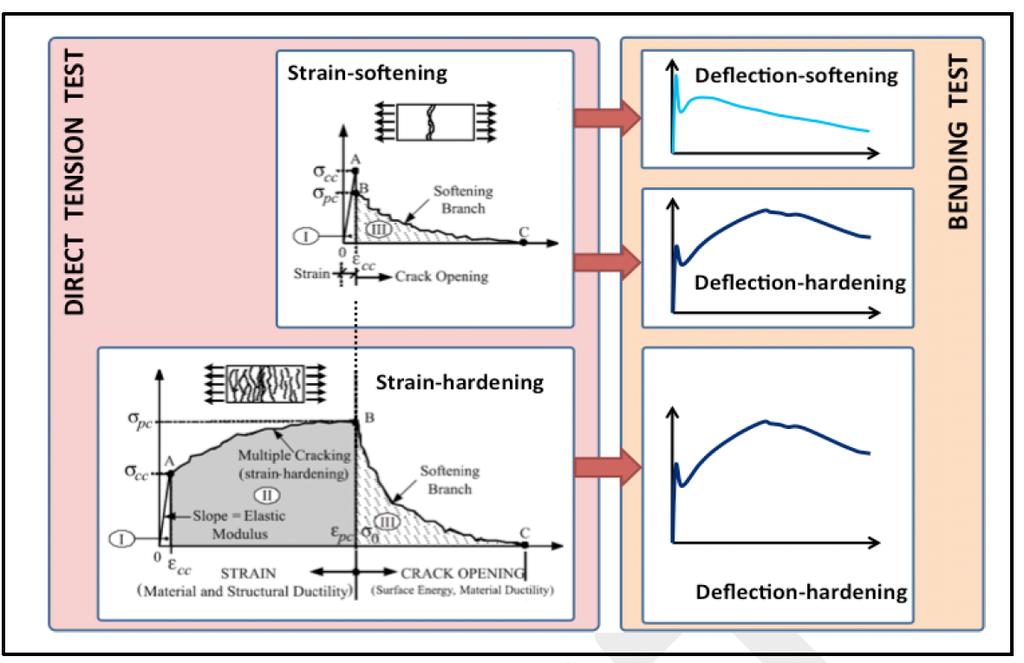
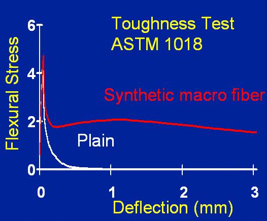
4 Fiber Reinforced Composites FRC: Substantially enhance the post-cracking response of the composite (toughness). Post-cracking response: is evaluated through toughness testing Toughness: area under the load deformation curve Strain Softening Materials

5 Toughening Modes for FRC Depending on the type, length, properties, and content of fibers, the tensile (or flexural) response of FRC may vary. 1) Damage of the matrix 2) Fiber/matrix debonding 3) Fiber bridging 4) Fiber failure 5) Fiber pull-out
6
7 KEY PROPERTY : Stress-strain diagram Stress Stress F c RILEM TC162 F c 10 % 1 % F ct,,3 0.37F eq ct, eq,1.5 Strain F ct, ax Strain F ct, ax Fiber Reinforced Concrete Plain Concrete Fct,eq,3 Fct,eq,1.5 Equivalent strength at deflection of 3 mm (L/150) Equivalent strength at deflection of 1.5mm (L/300)

8 Stress Post-cracking behavior The cracked section of fiber-reinforced concrete (FRC) does carry tensile load while plain concrete becomes ineffective after cracking as indicated in the stress-strain diagram Z Z Conventional RC FRC F c 10 % 1 % F ct, 0.37F eq,3 ct, eq,1.5 F ct, ax Strain Need to be characterized

9 Direct tensile test on FRC is difficult, instead, the residual tensile strength is derived from the measured flexural strength by means of conversion factors. Tensile Test is not Standard Difficult to perform in a consistent way
10 Toughness tests ASTM C1609/C1609M (JCI-SF4) (Standard Test Method for Flexural Toughness and First- Crack Strength of Fiber-Reinforced Concrete (Using Beam With Third-Point Loading) 100 mm by 100 mm by 350 mm beam 150 mm by 150 mm by 500 mm beam ASTM C1399/C1399M (Test Method for Obtaining Average Residual-Strength of Fiber-Reinforced Concrete) 100 mm by 100 mm by 350 mm beam ASTM C1550 (Standard Test Method for Flexural Toughness of Fiber-Reinforced Concrete (Using Centrally Loaded Round Panel)) 75 mm thick, 800 mm diameter round panel ASTM C (Standard Test Method for Flexural Toughness and First-Crack Strength of Fiber- Reinforced Concrete (Using Beam With Third-Point Loading)

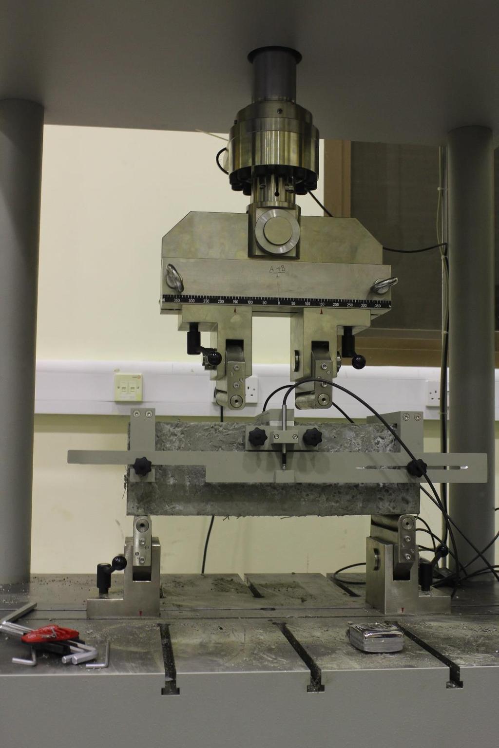
11 ASTM C-1609 Standard Test Method for Flexural Performance of Fiber-Reinforced Concrete This test method evaluates the flexural performance of fiber-reinforced concrete using parameters derived from the loaddeflection curve obtained by testing a simply supported beam under third-point loading using a closed-loop, servo controlled testing system.

12 ASTM C-1609 Standard Test Method for Flexural Performance of Fiber-Reinforced Concrete This test method provides for the determination of first-peak and peak loads and the corresponding stresses calculated by inserting them in the formula for modulus of rupture. It also requires determination of residual loads at specified deflections, and the corresponding residual strengths calculated by inserting them in the formula for modulus of rupture. At the option of the specifier of tests, it provides for determination of specimen toughness based on the area under the load-deflection curve up to a prescribed deflection To determine the first-peak, peak and residual strengths the respective load value is substituted in the modulus of rupture formula: Values of loads at specified deflection points are used for measuring residual strength of FRC f = PL bd 2 Where: f = the strength, MPa (psi), P = the load, N (lbf), L = the span length, mm (in.), b = the average width of the specimen, mm (in.), at the fracture, and d = the average depth of the specimen mm (in.), at the fracture.
13 ASTM C-1609 Standard Test Method for Flexural Performance of Fiber-Reinforced Concrete Residual Loads and Corresponding Residual Strengths 350 x 100 x 100 mm ( 14 x 4 x 4 in.) 500 x 150 x 150 mm ( 20 x 6 x 6 in.) P 150,0.75 the load value corresponding to a net deflection equal to 1/600 of the span (or 0.75mm in.) using a specimen with a depth of 150 mm (6 in.). f 150,0.75 the stress value obtained when the residual load P 150,0.75 is inserted in the formula for modulus of rupture. P 100,0.5 the load value corresponding to a net deflection equal to 1/600 of the span (or 0.5mm in.) using a specimen with a depth of 100 mm (4 in.). f 100,0.5 the stress value obtained when the residual load P 100,0.5 is inserted in the formula for modulus of rupture. P 150,3.0 the load value corresponding to a net deflection equal to 1/150 of the span (or 3.0mm in.) using a specimen with a depth of 150 mm (6 in.). f 150,3.0 the stress value obtained when the residual load P 150,3.0 is inserted in the formula for modulus of rupture. P 100,2.0 the load value corresponding to a net deflection equal to 1/150 of the span (or 2.0mm in.) using a specimen with a depth of 100 mm (4 in.). f 100,2.0 the stress value obtained when the residual load P 100,2.0 is inserted in the formula for modulus of rupture.

14 L/3 L =3*H B H P( N)* L( mm) flex ( MPa) 2 B( mm)* H 2 ( mm ) Residual Strength at 3 mm deflection depends on the dosage of fibers
15 ASTM C-1609 Standard Test Method for Flexural Performance of Fiber-Reinforced Concrete 500 x 150 x 150 mm 350 x 100 x 100 mm Specimen toughness, T 150,3.0 the energy equivalent to the area under the loaddeflection curve up to a net deflection of (1/150) of the span (3.0 mm 0.12 in.) using a specimen with a depth of 150 mm (6 in.). Specimen toughness, T 100,2.0 the energy equivalent to the area under the loaddeflection curve up to a net deflection of (1/150) of the span (2.0 mm 0.08 in.) using a specimen with a depth of 100 mm (4 in.).
16 Flexural Stress 16 Equivalent flexural strength, f e,3 f p f e,3 Deflection (mm) 3, (L/150) Equivalent Flexural Strength: Have the same toughness, T 150,3.0, obtained from experiment to a deflection of L/150 (same area under load-deflection curve) ASTM C JSCE, JCI-SF4 NBN B f e,3 (MPa) = For Span, L= 450 mm f e,3 L( mm) T150,3.0 ( Nmm) L( mm) W(mm) D(mm) T = 3 W D 150, T W D 150,3.0 2 fe,3 R e,3 (%) = 100 f p 2


17
 flex beam ASTM C1609-12 18")
18 Small (100 mm) versus big (150 mm) flex beam ASTM C

19 Small (100 mm) versus big (150 mm) flex beam ASTM C Residual strength is lower when measured with big flex beams!!
20 ASTM 1609 Provides Equivalent Flexural Strength F e,3 for Strength Design Residual Strength of FRC At L/600 deflection ( for serviceability design) At L/150 deflection( for ultimate strength design) Used to characterize stress strain curve for section analysis Toughness ( area under the load deflection curve) Compare performance of different fibers Care must be practiced when assess flexural beams with small size
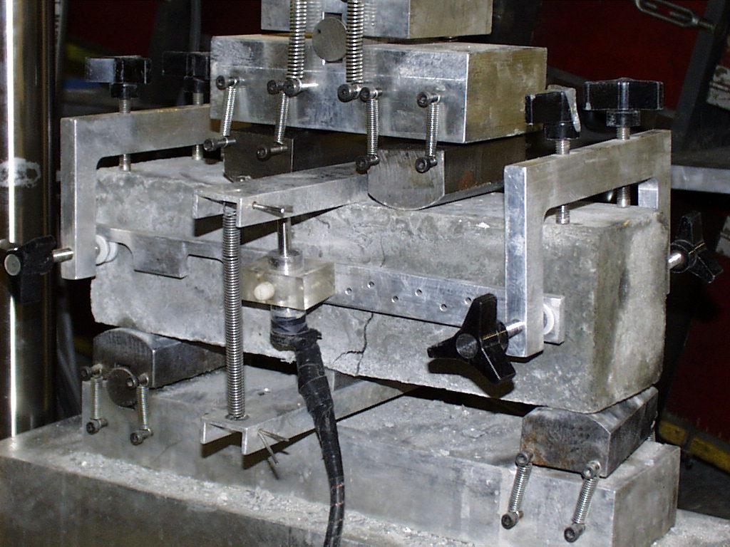
21 ASTM C-1399 Test Method for Obtaining Average Residual- Strength of Fiber-Reinforced Concrete (100 mm x 100 mm x 350 mm) Flexural Beam The testing shall be done using the third-point loading apparatus specified in Test Method C-78 with the modification of the steel plate used in the initial loading cycle. The steel plate is used to help control the expected high rate of deflection when the beam cracks. Closed-loop feed-back controlled deflection apparatus is not required.
22 Load, N Average Residual Strength Evaluation ASTM C1399 Initial loading Curve (Stop initial loading after beam cracking or 0.5 mm deflection) ASTM C Average Residual Strength(ARS) ARS = ( (P A + P B + P C + P D ) /4 ) x K K= L / bd 2 L /3 b d P A + P B + P C + P D = sum of recorded load at specified deflection, N L A B C D Reloading Curve Beam Deflection, mm
23 ASTM C-1399 Test Method for Obtaining Average Residual- Strength of Fiber-Reinforced Concrete Two stage test: 1. Using a steel plate underneath the entire length, the beam is initially cracked from an applied load up to a deflection of between a minimum of 0.25 mm (0.01 in.) and a maximum of 0.5 mm (0.02 in.). 2. The steel plate is then removed and the cracked beam then reloaded up to a deflection of 1.25 mm (0.05 in.) as measured from the beginning of reloading.
24 ASTM C-1399 Test Method for Obtaining Average Residual- Strength of Fiber-Reinforced Concrete 1. Initial loading curve the load-deflection curve obtained by testing an assembly that includes both the test beam and a specified steel plate. Two curves plotted: 2. Reloading curve the load-deflection curve obtained by reloading and retesting the pre-cracked beam, that is, after the initial loading but without the steel plate.
25 ASTM C-1399 Test Method for Obtaining Average Residual- Strength of Fiber-Reinforced Concrete The average residual strength is calculated using loads at reloading deflections of 0.50, 0.75, 1.00, and 1.25 mm ARS = ((P A + P B + P C + P D ) /4) x k where: k = L/bd 2, mm 2 (in 2 ) ARS = average residual strength, MPa (psi), P A + P B + P C + P D = sum of recorded loads at specified deflections, N (lbf), L = span length, mm (in.), b = average width of beam, mm (in.) and d = average depth of beam, mm (in.) Note. This test cannot determine the flexural strength of the FRC.
26
27 Important points to remember: If ASTM C / C1609/C1609M test on small flex beams (100 mm x 100 mm x 350 mm) can be controlled in terms of crack development, the equivalent flexural strength, f e,2, and Average Residual Strength, ARS, are within 10% and therefore can be considered equivalent. Disadvantages of ASTM C1399/C1399M: Does not tell you flexural strength NO information about what happens right after crack initiation Only uses small flex beams Larger specimens are more representative for slab on ground applications Similar specimen thickness (150 mm thickness is common) Less artificial fibre alignment caused by the specimen molds and therefore more realistic fibre performance measurement Larger fibres (50 mm and more in length) require larger crack surface area


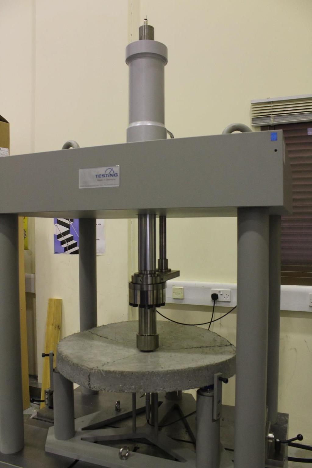
28 ASTM C 1550 Determination of flexural toughness of fiber-reinforced concrete (FRC) expressed as energy absorption in the post-crack range. Toughness is measured using a round panel supported on three symmetrically arranged pivots and subjected to a central point load. Load and deflection are recorded simultaneously up to a specified central deflection. The energy absorbed by the panel up to a specified central deflection is representative of the flexural toughness.

29


30 ASTM C 1550 Such a test panel experiences bi-axial bending which exhibits a mode of failure related to the in situ behavior of structures. The nominal dimensions of the panel are 75 mm in thickness and 800 mm in diameter. The testing machine should operated such that the piston advances at a constant rate of 4.0 +/- 1.0 mm/min up to a central displacement of at least 45.0 mm.

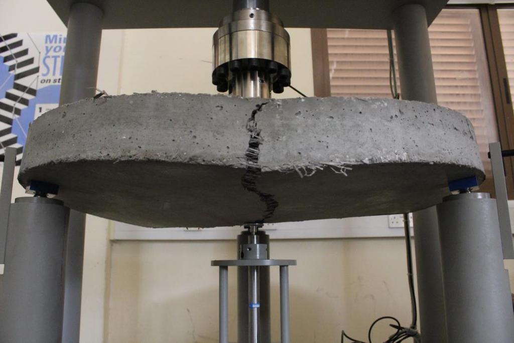
31 Round panel after loading Larger fracture surface area minimizes standard deviation Behaviour of thin panel does not simulate slab-on-ground action

32
33
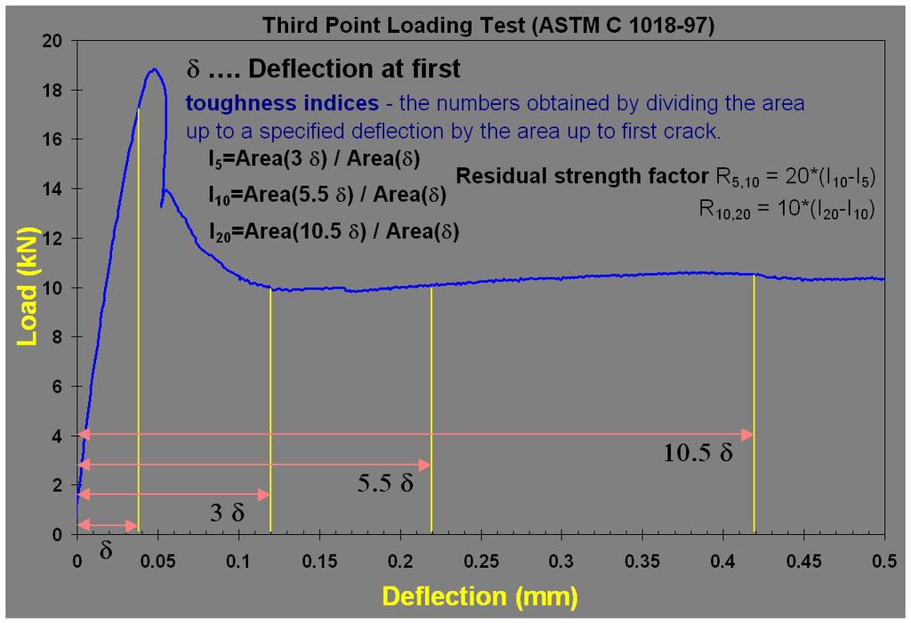
34 Definition of toughness indices

35 I 5 I 10 I 20 d 3*d 5.5*d 10.5*d

36

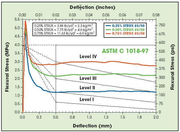
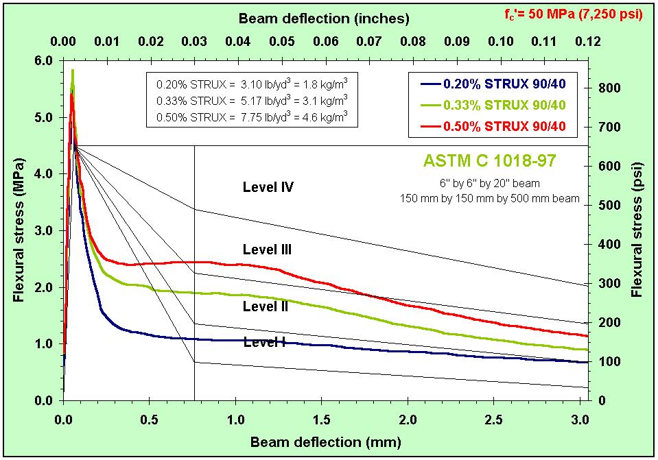
37 ( psi) P( N)* L( mm) flex ( MPa) 2 B( mm)* H 2 ( mm ) Level system template was developed by Rusty Morgan et. al. (not part of ASTM)

38 Toughness Level and Residual Strength Depends on the type and dosage of Fiber

39
40 Problems Instability issues - low stiffness of the testing apparatus and poor control of the test can cause brittle failure (sudden drop of load) Toughness indices and residual strength values are not sizeindependent - values measured on 4 by 4 by 14 beam are much bigger compared to values measured on 6 by 6 by 20 beams (alignment of fibers) Crack pattern varies (starting point, end point), which causes high standard deviation Small fracture surface area compared to large volume of concrete - low number of fibers are bridging the crack
41
42
43

44 Prof. Salah Altoubat Coordinator