US 84 Mississippi River Bridge
|
|
|
- Ross Watson
- 5 years ago
- Views:
Transcription


1 US 84 Mississippi River Bridge U29 And U49 Pin Rehabilitation Justin Walker, PE MDOT Director Of Structures, State Bridge Engineer James Gregg, PE HNTB Bridge Department Manager

2 Project Location Vicksburg, MS Natchez Baton Rouge, LA Houston, TX New Orleans, LA 2

3 Quick Facts WPA Project #1126 Constructed 1940 Built for: City of Natchez Total Cost $3,562, Dravo Corp. Sub. Bethlehem Steel Sup. Toll removed 12 years after bridge opening (1952) Twin Bridge Constructed in 1980 s 3


4 US 84 Mississippi River Bridge Pin And Link Replacement 4


5 5 US 84 Mississippi River Bridge Pin And Link Replacement
6 1940 Sequence Of Construction Span 5 Span 4 Span 3 Span 2 Span 1 Vidalia, LA Natchez, MS 5 Span truss bridge Main span (spans 2 & 3) = 875 ft Total length of truss = 3,664 ft 6
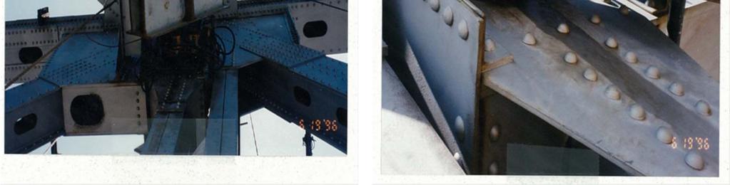
7 Location of Pins Link and Pin Anchor Arm Quasi-Suspended Spans Suspended Span Anchor Arm 7
8 Location of Lower Pins 10 Upper Pin (Pin is longer than lower pin) 10 x 16 x 7-6 Link 10 Lower Pin 8


9 U49 Lower Pin U49 Upper Pin U49 Lower Pin 9
10 U29 Lower Pin History ( ) 1995 MDOT observed U29 Upstream Truss Lower Pin had shifted Keeper that holds pin in place sheared off Pin had rotated Pin was close to flush with the gusset plates 1996 MDOT let a contract to reset U29 Lower Pin Contractor was unsuccessful after 4 attempts New Keeper installed and pin greased 10
11 Lower Pin History 2010 In-Depth Inspection (HNTB) U29 Upstream Truss Lower Pin Lower pin is flush with gusset Welds between pin and gusset is broken Pin is allowed to rotate about gusset U49 Downstream Truss Lower Pin Keeper Sheared Off U49 pin is flush with gussets. Welds between pin and gusset broken Pin is allowed to rotate about gusset 11
12 Lower Pin History 2010 In-Depth Inspection (HNTB) Ultrasonic Testing of Pins Acoustic coupling observed between link and pin on both pins Areas of high bearing Pin is possibly frozen with link Wear in gusset plates observed Gap below lower pin observed Finger joints are no longer flush Bulge in Gussets at Lower Pin observed (U49 and U29) 12
 East West")

13 U29 Downstream Truss (Upstream Side) East West Rotated 2 ¾ (Ave.) 13
 West")

14 U29 Downstream Truss (Downstream Side) West East Rotated 2 ¾ (Ave.) 14
 East")

15 U49 Upstream Truss (Upstream Side) East West Not measured (Ave.) 15
 West")

16 U49 Upstream Truss (Downstream Side) West East Not measured (Ave.) 16

17 1996 U29 Pin Rehabilitation Project 17
18 1996 U29 Pin Rehabilitation Project (Overview) 0 extension observed HNTB advised MDOT that pin could move another 1/2 before adversely affecting the Factor of Safety MDOT decided to reset U29 Lower Pin 18

19 1996 U29 Pin Rehabilitation Project (Contractor s Plan A) Installed 2 PT rod though the pin, placing compression blocks on the rod and jacking the pin with 4 jacks Results Jacking assembly jacked to 6,100 psi 1 st attempt, PT rods failed and landed in Mississippi River 2 nd attempt, PT rods failed No horizontal movement in pin was noted Pin Jacks PT Rod 19
20 1996 U29 Pin Rehabilitation Project (Contractor s Plan B) Increase jacking assembly to include 10 jack rams and 3 rods Vertical load not released from pin PT Rods Results Link Jacking assembly jacked to 8,000 psi (Horizontal force = 884 kips) No horizontal movement in pin was noted Jacks 20
21 1996 U29 Pin Rehabilitation Project (Contractor s Plan C) Increase the number of jacking assembly to include 12 jack rams and 5 jacking rods Vertical load not released from pin Results Jacking assembly jacked to 10,000 psi (Horizontal force = 1,325 Kips) No horizontal movement in pin was noted 21
22 1996 U29 Pin Rehabilitation Project (Contractor s Plan D) Basic concept was same as shown in contract plans 8 Jack rams and 8 Jack rods in vertical position and 7 Jack rams and 3 Jack rods in horizontal position Relieved dead load stress in the pin-link system Horizontal re-alignment of pin was unsuccessful Results Total Vertical Force = 733 kips to 830 kips (Design plan vertical dead load force = 656 kips) Total Horizontal Force = 727 kips Applied Horizontal Force > Estimated Vertical DL Therefore, assumed pin is jammed in the link 22
23 1996 U29 Pin Rehabilitation Project (Lessons Learned) Vertical load must be removed from Pin and Link Contractor should not have been allowed to reset pin without releasing the vertical load Traffic will affect load in link and pin Traffic was allowed on bridge during pin resetting Unsure if all load was removed from the link No means to ensure load was removed Excessive vertical PT force might put the link in compression Contractor did not attempt to rotate pin Rotating pin in direction of grooves might have helped 23
24 Pin Rehabilitation Project
25 Pin Rehabilitation Options Considered 3 options (Option 3 chosen) Option 1 Restrain and Monitor Low cost option that is less intrusive Option 2 Reset Pins Repeat of the 1996 attempt Option 3 Replace Pin Replace lower pin but not link Option 4 Replace Lower and Upper Pins and Links Remove and replace existing pin with new pin and hexagonal recessed nuts Option Chosen by MDOT and Louisiana DOTD 25
 Spandrel arch truss bridge")
26 Background Replacing U29 and U49 Lower Pins Not many successful examples of resetting or replacing highway truss pins Railroads have successfully completed pin replacements but pins typically do not have as much dead load as highway bridges Most examples are stringer/ girder pins Key to success is locking joint and creating a bypass Gay Street Bridge (Knoxville, TN) Spandrel arch truss bridge Replaced 125 pin joints and gussets Created a pin bypass Regional steel contractor awarded project Bridge Closed during rehabilitation 26
27 Pin Rehabilitation Option 4 Replace Link and Pins Create bypass Lock Joint from moving Remove link and pins Install new link and pins Remove bypass 27
28 Pin Rehabilitation Option 4 Replace Link and Pins Create bypass Lock joint from moving Remove link and pins Install new link and pins Remove bypass Bridge to be closed to traffic during replacement Low ADT Two way traffic on new bridge 28
29 Pin Rehabilitation Option 4 Replace Link and Pins Cantilever Span Suspended Span Upper Longitudinal Restraint Diagonal Bypass Lower Longitudinal Restraint Bypass Load Path A 29
30 Pin Rehabilitation Option 4 Replace Link and Pins Cantilever Span Suspended Span Splice Plate Shims Bypass Load Path B 30
31 Pin Rehabilitation Option 4 Replace Link and Pins Diagonal Bypass Link Upper Pin Shims Upper Long. Rest. Splice Plate Lower Pin 31
32 Pin Rehabilitation Option 4 Replace Link and Pins Suggested Sequence Of Construction 1. Install & tension upper and lower longitudinal restraints 2. Install & tension diagonal bypass 3. Install splice plate a) Use template and field drill holes 4. Remove pin and link a) Bore pins past existing gusset b) Cut link from top to remove any remaining load 5. Install new pin and link 32

33 Pin Rehabilitation Option 4 Replace Link and Pins Remove Link and Pins Remove plate Remove top lateral plate Cut Link from the top Remove plate Link 33
34 US 84 Mississippi River Bridge Pin Rehabilitation Pin Rehabilitation Option 4 Replace Link and Pins Construction Two Tier Selection Tier I Contractor Request for Qualifications Advertised 5/19/14 Shortlist Contractors (min of two) September 11, 2014 Submission of Bids October 28, 2014 Pin Replacement Spring/ Summer 2015 Target Completion date July


35 US 84 Mississippi River Bridge Pin Rehabilitation Questions? 35