For the purpose of illustrating key concepts, the authors of the SA Site Handbook have used extracts from the RMD Technical Data Sheets.
|
|
|
- Erick Ellis
- 5 years ago
- Views:
Transcription


1 J First Edition 1
2 CONTENTS INTRODUCTION FORMWORK SYSTEMS AIRODEK Airodek Panels Airodek Prop Airodek Load Release Pin Airodek Crown Temporary Prop (Assembly Prop) Airodek Prop No 2 Cap Spigot Leg Tripods Spacing Gate Spacing Gate Leg Decking Beams Infill Beams Prop Head Timber Support Drophead Drophead Panels Drophead Infill Plate Airodek Infill Bracket Airodek Support Block Alshor Adaptor Alshor Airodek U-Head Airodek Rapidshor Adaptor Alshor Plus U Head Airodek Crown Guardrail Socket Rapidshor Decking Beam Guardrail Socket Drophead Guardrail (Handrail) Bracket Airodek Panel Strap Ratchet tie down strap Airodek Panel Handling Hook Airodek Upper Restraint Unit Airodek Prop Head Adaptor Airodek GTX Locator Bracket
3 Slab Edge Detail Drop Edge Beam Preparation for Erection Airodek Temporary Prop Prop Pin Connection Edge Support to Crown Connection Downstand Beam Support Airodek layout of support to corner of building Airodek make up around columns Connection of Spacing Gates to Props Airodek Gate and Gate Leg positions on a typical plan Airodek on Rapidshor Tower Patching MINIMA Minima Panels Multi Purpose Panels Multi Purpose Composite Panel HD Minima Alignment (Adjusting) Props Hinged Corners Inner Corners Minima Wedge Clamp Adjustable Clamp Minima Aligning Panel Clamp Corner Clamp Crane Hook Edge Tie Bearing Minima Access Bracket Minima Guardrail Post Minima Waler Components Ground Plate Centre Tensioning Bolts Minima Prop Clamp Connector Minima Universal Prop Adaptor Minima R Strut Connector
4 Push Pull Prop Long Minima Panels Technical Information Minima Accessories Technical Information Minima Panel Connections Minima Panel Infill Connections Minima Corner Details Minima Access Minima Medium & Short Alignment Prop Minima Crane Hook PARASLIM Paraslim Member Capacities Tie Angles GTX BEAMS, CLAMPS AND SPLICES GTX Beams GTX to Soldier Clamp Guardrail Post GTX Restraint Unit Hook Clamp GTX Swivel Clamp Saddle Clamp GTX Wedge Clamp Cross Head Spigot Outside Corner Bracket GTX Splice Plate GTX U-Plate GTX Forkhead Cup Spigot Plywood SUPERSLIM Superslim Soldiers Open ended Soldier Corner Soldier Universal Clamp GTX to Soldier Clamp B Clamp
5 C Clamp Way Connector kn Prop Connector Anchor Plate 15mm Corner Angle Superslim 45 Corner End Angle Waler Plate Corner Pivot Pivot Corner 20mm Pivot Cleat Set Prop Spade End Link and Prop Pivot Tube Prop Tube End Link R Clip Tilt Plate Tilt Plate/Double Prop Foot Superslim Left Hand and Right Hand Prop Jacks Superslim Soldier Jack Lifting Plate Spreader Beam Plate Klik Klak Wall Bracket and Latch Rocking Head Adjustable base Roller Adaptor Plate Turnbuckles Joint Stiffeners Access Bracket Porthole Bearing Hillman Standard Roller Lower Pivot The Superslim Soldier Superslim Soldier Accessories Connection Details Punchings and Geometry Superslim Joint Stiffeners
6 Superslim Lifting Plate 15kN Superslim Access Bracket Superslim Turnbuckle & Superslim Plumbing Foot B Clamp Half Coupler Universal Clamp Flange to Flange Wedge Clamp Waler Plate Heavy Duty Waler Plate Angle 3/ Waler Plate Hi-Load Porthole Bearing Superslim Adjustable Base Superslim Corner Pivot Prop Spade End Link & Prop Pivot Tube Superslim Prop Connector 100kN Superslim Prop Tube End Link Superslim Prop Jacks Superslim Tilt Plate Superslim 90 Degree Corner Superslim Pivot Cleat Set Superslim 45 Deg Corner Superslim Pivot Corner 20mm Way Connectors in use Superslim Anchor Plate 15mm Superslim Klik-Klak Latch Superslim Klik-Klak Wall Bracket Klik-Klak Wall Pocket Lifting - Spreader Beam Adaptor Assembly Lifting Spreader Beams Single Sided Formwork SHORING SYSTEMS ALSHOR PLUS Legs Leg Tripod
7 Jacks U-Plate U-Head Alshor Superslim Clamp Base Plate Bracing Frames Straight Pin Jack Spanner Guardrails (Handrails) Board Bearers Castor Unit Twin pronged C-Hook Alshor Plus Leg Range Connection Details Jacks Long Jack Load Release Mechanism Jack Spanner Short Jack U-Plate Bracing Frames Handrails Board Bearers Alshor Plus Leg Tripod Adjustable Pocket Assembly Castor Unit Alshor Superslim Clamp U-Head 220w x 10mm Base 10mm MEGASHOR Megashor Legs End Plate Screw Jack Jack Spanner
8 Jack Plate Hydraulic Unit Plate Washer Rocking Head Brace Plates Flat Bracing Packer Plate Megatruss Bearing Plate Megashor Superslim Adaptor Megashor U Head Torque Wrench Megashor Plan Brace Cleat Megashor Header Beam Megatruss Intermediate Bearer Megashor Joint Stiffener Megashor Truss Connector Megatruss End Bearer Megatruss Node Megashor Medium Prop Frame Megashor Joints Allowable Axial loads in Tension Megashor Joints Bolting Superslim to Megashor Connection Bending & Shear Capacity Tensile and Compressive Capacity at Node Points Megashor Jack mm Megashor Loading and Unloading Megashor Jack Spanner Megashor End Plate Megashor Rocking Head 180mm Prop Tube End Link Short Prop Tube End Link Tube End Link Loading Graph Megashor Joint Stiffener Megashor M52 Tools Megatruss Node
9 Megatruss Node Connections Node to Chords Megatruss Node Connections Node to Diagonals Megatruss Node Connections Node to Cross Brace Megatruss Node Connections Node to Ledger Megatruss Node Connections Node to Prop/Tie Megatruss Node Connections Ledger to Plain Brace Megatruss End Bearer Megatruss End Bearer Connections Bottom Chord Supported Truss Megatruss End Bearer Connections Top Chord Supported Truss Megatruss Double Chord Connections Chord to Chord Megatruss Intermediate Bearer Megatruss Intermediate Bearer Connections Vertical Applications: Individual Props Vertical Applications: Trestles Vertical Applications: Towers Inclined Props: 45 Support Inclined Props: Bridge Abutments Megashor Assembly Guidance Megatruss Assembly Guidance PROPS ADJUSTABLE STEEL PROPS Airodek Prop ADJUSTABLE PROP ACCESSORIES Sleeve Clip PRJ Prop to Airodek Crown Adaptor Leg Tripod PUSH PULL PROPS SUPERSLIM PROPS PUSH PULL PROP ACCESSORIES RAPIDSHOR Rapidshor Standards Rapidshor Sleeves Rapidshor Clip Rapidshor U-Plate
10 Rapidshor Base Rapidshor Brace U-Head Tilt Base Tilt Head Rapidshor Jack Rapidshor Ledgers Board Bearers Fixed Braces Adjustable Jack Braces Adjustable Bay Braces Rapidshor Standards Rapidshor Jacks Rapidshor Ledgers Bracing Over Multiple Bays Double and Reversed Bracing Skewing the Falsework Grid Effect on Loads to Standards Effect on Braces Rapidshor Leg Make-Ups SCAFFOLD SYSTEMS KWIKSTAGE Kwikstage Shoring and Access Kwikstage Standards Kwikstage Ledgers Hook on Board Steelboard Series Toeboard Series Toeboard Clip Kwikstage Staircase Kwikstage Staircase Handrail Kwikstage Steel Ladder Series (Hook-on) Trapdoor Kwikstage Connectors Kwikstage Base Jack Kwikstage Base Plate
11 Scaffold Tube Kwikstage Column Formwork C-Type Column Side Kwikstage Circular Columns PMI Wedge Sets Economy Wedge External Corner Angles Kwikstage Shoring and Formwork Double Headed Jack Kwikstrip Beam Kwikstrip Deck Panel Kwikstrip Folded Section Cantilever Bracket Kwikstage Fork Head and U-Head Jacks Form Support Bracket Form Wall Bracket Kwikstage Coffers Kwikstage Bracing and Lacing Kwikstage Band and Plate B Clamp C Clamp Kwikstage Diagonal Brace Couplers Kwikstage Safety Kwikstage Back to Back C Press Kwikstage LD Handrail Clamp Kwikstage Miscellaneous Kwikstage Pallet Kwikstage Stillage Stop End Bracket Kwikstage Technical Information Kwikstage Erecting Procedures ULTRAGUARD Barriers
12 Post Beam Bracket Slab Edge Clamp Soldier Socket Extended height guardrails TIE SYSTEMS RAPID BAR TIE Rapid Bar Tie 15mm and 20mm Waler Plate HD Hi-Load Waler Plate Rapid Bar Tie Wing Nuts Plastic Ferrule Tubing Rapid Bar Tie Cones Rapid Bar Tie Connectors Rapid Bar Tie Hexagonal Nuts Formpad Ribbed Connectors Water Bar Dynabar Ferrule Jack Plastic Buttons Steel end safety stub cap Anchor Screw Form Support Bracket Form Wall Bracket Concrete Anchor Threaded Rod Steel Rapid Bar Tie Properties Rapid Bar Tie Water Bar Properties ANCHOR SCREWS MEASUREMENT WORKING WITH RMD KWIKFORM Introduction Frequently Asked Questions Terms and Conditions
13 Branch Contact Details PRODUCT INDEX
14 INTRODUCTION RMD Kwikform RMD Kwikform is a customer driven business providing innovative and cost effective solutions for all formwork, shoring and falsework requirements. With a diverse product range and ongoing technical software development, coupled with our determination to provide a high quality service and engineering excellence, we work in partnership with our customers throughout the construction cycle to ensure the project finishes on time and on budget. For over 65 years, we have provided formwork and shoring solutions for the construction and related industries throughout the world, including: Commercial Building Roads Civil Engineering Utilities High Rise Buildings Mining Entertainment Stadiums Bridges Retail Quality Assurance RMD Kwikform is accredited to ISO 9001:2008 Quality Systems, for design, development, production, installation and servicing. Our company-wide commitment to quality and our aim to exceed our customers expectations, helps us to hire and sell a consistently high standard of construction equipment and provide an exceptional level of service, which leads to higher customer satisfaction. Health & Safety Health and safety underpins everything we do. The designs we produce not only meet customers construction requirements, they also ensure the safe erection, movement and dismantling on site, as well as the safety of the site operatives throughout the project. All RMD Kwikform staff are trained on best working practices in regard to health and safety, and are aware of the company s Senior Managements commitment to safe working practices. All RMD Kwikform equipment is fully supported with technical data sheets, equipment guidance notes and application risk assessments to ensure everyone working with RMD Kwikform equipment is fully aware of the equipment limits, safe erection and dismantling and safe transport of equipment to and from site. Underpinning all RMD Kwikform operations is our global Safety Management System, which all businesses adhere to, so no matter where our customers are, they are guaranteed maximum, consistent safety levels when working with RMD Kwikform. 14

15 RMD Kwikform Network To maximize the service levels we can provide to our customers, RMD Kwikform has a network of offices throughout the world, strategically located to provide local design, sales and equipment supply facilities. The network ensures we re only a step away to support on site operations and respond quickly and effectively to our customers needs. Engineering Services RMD Kwikform has its design capability spread throughout the region, in order to maximize local engineering support. With an eye on continuous improvement, ongoing training and development programs, and best practice shared throughout our global engineering network, we are able to provide solutions that are tailored to our customer s exact requirements. Customer Service Equipment hire is just one of the ways in which RMD Kwikform adds value. Apart from helping customers to eliminate high capital expenditure, and the future need to maintain and store redundant equipment, RMD Kwikform provides a range of support services that support customers on-site. These include assessment of project needs, assistance with value engineering, detailed commercial and engineering proposals, engineered erection drawings, method statements and design calculations and dedicated site assistance for the duration of the project. Product training for on-site operatives is also provided. All technical recommendations meet the British Standards for formwork and shoring that are current at the time of printing. 15

16 Airodek FORMWORK SYSTEMS AIRODEK High Productivity Soffit System Airodek is based on a single principle simplicity. Airodek has been designed for easy assembly, transportation, storage and maintenance. It is a low-weight, high productivity, simple slab formwork system, suitable for slabs up to depth of 450mm. Airodek provides an F2 soffit finish and supports concrete slabs up to 450mm thick. All components are under 25kg making for ready man handling The quick, safe and simple assembly process enables one man to erect up to 40m2 in an hour, significantly reducing construction time and labour requirements and thereby customers costs. The maximum concrete slab thickness that can be supported is 450mm. The maximum additional live load is 2.0kN/m2. Key Features & Benefits: Speed: Reduced construction times due to simple assembly process. Lightweight: Airodek has 30% less weight and 40% fewer parts than conventional props and timber. Safety: Erection from below the soffit, minimising safety hazards associated with erecting panels from above. Simple Connections: the unique Airodek Crown simultaneously locates the corners of up to 4 panels, ensuring the panels cannot easily be dislodged, increasing site safety. Lower Costs: Powder coated panels minimise cleaning and maintenance costs. Quick Strip: System where panels and deck beams are removed during the early stages of concrete curing, results in higher re-use of panels and beams, reducing the total amount of soffit formwork required. Design If 600 and 300 panels are used to the max, concrete slab thickness that can be supported is increased to 700mm. 16
 ADX18090 ADX18091 Panel 1800mm x 900mm 24.21 ADX18060 ADX18061 Panel 1800mm x 600mm 21.20 ADX18030 ADX18031 Panel 1800mm x 300mm 12.")

17 Airodek Airodek Panels An aluminium framework with either 10mm thick phenolic faced hardwood or alkus composite board inlaid into the frame for a smooth finish and long life. Plywood Composite Description Weight (kg) ADX18090 ADX18091 Panel 1800mm x 900mm ADX18060 ADX18061 Panel 1800mm x 600mm ADX18030 ADX18031 Panel 1800mm x 300mm ADX09090 ADX9091 Panel 900mm x 900mm ADX09060 ADX9061 Panel 900mm x 600mm ADX09030 ADX9031 Panel 900mm x 300mm 6.62 Note: 1800 x 900 Panel may be used for slabs up to 450mm thick. The maximum additional live load is 2,0kN/m². Airodek Prop Airodek Props are used to support the Airodek Panels and Infill Beams ADX20005 Airodek Prop Range: 1980mm 3350mm (prop only) Range: 2190mm -3490mm (top of panel) Airodek Load Release Pin Supplied integral to the Prop, the Prop Pin allows quick release of the applied load in the props by lowering the Panel and inner section of the prop by 4mm, enabling easy and damage-free removal of Airodek Panels. Code Description Weight (kg) ADX20012 Airodek Load Release Prop Pin 0.8 Airodek Crown Used to support and locate the Airodek Panels on the top of the Props. Secured to the top with a Sleeve Clip. ADX20015 Airodek Crown 1.43 RSX10009 Sleeve Clip


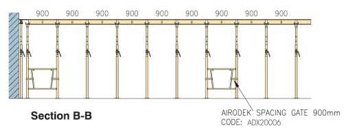
18 Airodek Temporary Prop (Assembly Prop) Used at an angle of approximately 25 to support one end of the Airodek Panels temporarily prior to the erection of the Airodek Props. ADX20013 Airodek Temporary Prop 4.17 Range: mm Airodek Prop No 2 Cap Spigot The Cap Spigot is used to support the first Airodek panel placed at the corner of the building. It enables the Airodek panel to be placed flush to the walls reducing the need for a timber infill. SIJ10035 Airodek Prop no 2 Cap Spigot 2.40 Leg Tripods Used to stabilise Airodek props in vertical falsework application without spacing gates and founded on a level surface. ASX10060 Alshor Leg Tripod 11.0 ASJ10060 Leg Tripod 13.0 Spacing Gate The Spacing Gates are attached to the lower section of the props to give the correct spacing. Only light use of a hammer is necessary to lock the gates in position. ADX20006 Spacing Gate 900mm 6.77 ADX20007 Spacing Gate 1800mm 9.56 Note: Do not use as a support for access platforms etc. Spacing Gate Leg The Spacing Gate Leg is attached to the Spacing Gate to support the props. They are used when the first row of props are being erected. ADX20008 Airodek Spacing Gate Leg 2.38 Note: Spacing Gate Legs should not be removed without the Spacing Gate being loosened on the props. 18


 ADX20011")
19 Decking Beams Airodek Decking Beams locate onto Crowns or Dropheads and provide support and alignment to the Panels. ADX31800 Airodek Decking Beam 1800mm ADX32400 Airodek Decking Beam 2400mm ADX33000 Airodek Decking Beam 3000mm Airodek Infill Beams Infill Beams are used to fill around columns and to support one edge of infills against walls. The Infill Beams locate in either the Crown or the Drophead. ADX20003 Airodek Infill Beam 1800mm ADX20004 Airodek Infill Beam 900mm 7.3 Prop Head Timber Support This unit will clip into a Crown adjacent to a wall. A timber beam can be placed on top with a strip of plywood to complete the infill area between the Panel and the wall (requires ply & timber make up = 100mm) ADX20011 Prop Head Timber Support 0.5 Drophead For use on slabs where undisturbed back propping is required. The 70mm stripping clearance allows for early removal of the Decking Beams and Panels. ADX30001 Airodek Drophead 7.9 ADX10016 Airodek to Alshor Drophead
 ADX30003 ADX40001 Drophead Panel 1800mm x 300mm 13.0 ADX30004 ADX40002 Drophead Panel 900mm x 300mm 7.")
. ADX30005 Airodek Drophead Infill Plate 0.")

20 Airodek Drophead Panels Drophead Panels are designed to fit around the Drophead, allowing them to be removed without removing the supporting props. Plywood Composite Description Weight (kg) ADX30003 ADX40001 Drophead Panel 1800mm x 300mm 13.0 ADX30004 ADX40002 Drophead Panel 900mm x 300mm 7.1 ADX30006 ADX40005 Drophead Panel 1800mm x 600mm 19.0 ADX30007 ADX40006 Drophead Panel 900mm x 600mm 10.1 Drophead Infill Plate Fits into the V notch of the drop head panels. Allows easy fit of the back prop adapter (with prop support). ADX30005 Airodek Drophead Infill Plate 0.21 Airodek Infill Bracket Used to support cantilever infill section ranging between 135mm to 320mm. Used in conjunction with the Airodek support block. ADX20026 Airodek Infill Bracket 2.14 Airodek Support Block Hooks onto the Airodek HD crown to support the Airodek infill bracket. ADX20027 Airodek Support Block 0.81 Alshor Adaptor Transition unit providing adaptability of Drophead with Alshor Plus shoring system. Secured to Drophead using Sleeve Clip. ADX30002 Airodek Alshor Adaptor 4.12 RSX10009 Rapidshor Sleeve Clip

21 Alshor Airodek U-Head Used to support Airodek deck beams in perimeter applications where the opposing end of the beam is supported by either an Airodek Crown or and Airodek Alshor Plus Drophead. Airodek ASX10066 Alshor - Airodek U-Head 4.24 Airodek Rapidshor Adaptor Transition unit providing adaptability of Drophead with Rapidshor shoring system. Secured to Drophead using Sleeve Clip. ADX10003 Airodek Rapidshor Adaptor 2.30 RSX10009 Rapidshor Sleeve Clip 0.09 Alshor Plus U Head Used to support primary beams in flat soffit applications where height adjustment is not required. ASX10015 Alshor Plus U Head 220w x 10mm 6.58 Airodek Crown Guardrail Socket The Crown Guardrail socket is used to allow the connection of perimeter edge protection to the falsework as required. Rapidshor standards and ledgers are used as the edge protection, with toeboards. ADX20018 Airodek Crown Guardrail Socket 5.43 Guardrail Post Guardrail Bracket Rapidshor Decking Beam Guardrail Socket The Drophead Guardrail Socket is used for Airodek applications incorporating a drophead. The bracket hooks onto the Airodek drophead. Rapidshor standards are then used as guardrails to create the handrail system. ADX20016 Rapidshor Decking Beam Guardrail 5.85 Socket Guardrail Socket 21

22 Airodek Guardrail Post Drophead Guardrail (Handrail) Bracket Guardrail The Drophead Handrail Bracket is used for Airodek applications incorporating Bracket decking beams and dropheads. The bracket incorporates a hook and lock system to secure it on the drophead. Rapidshor standards are then used as guardrails to create the handrail system. ADX10004 Drophead Guardrail Bracket 7.88 Guardrail Socket Airodek Panel Strap Used to secure Airodek panels to decking beams to resist wind uplift. ADX10008 Airodek Panel Strap 0.22 Ratchet tie down strap Used as an edge restrained system to tie down the Airodek system around the parameter of a building. ADJ10002 Ratchet tie down strap 0.00 Airodek Panel Handling Hook Used to handle panels at height by hooking onto panels for ease of moving. ADX10010 Airodek Panel Handling Hook 3.37 Airodek Upper Restraint Unit Upper Restraints locates via a mushroom bolt on rear of cantilevered beams for overturning/side form load restraint. ADX20019 Airodek Upper Restraint Unit
23 Airodek Prop Head Adaptor Airodek ADX20025 Airodek Prop Head Adaptor A.P ADJ20025 Airodek Prop Head Adaptor A.P Airodek GTX Locator Bracket Used on top of GTX beams to create a locator for Airodek panels. ADJ10001 Airodek-GTX Locator Bracket 1.36 Slab Edge Detail 23
24 Airodek Drop Edge Beam The Edge Beams are supported by falsework independent to the prop and panel system, providing beam side edge formwork and a walkway. Preparation for Erection Adjust all of the props to the approximate length required. This will be the floor to the ceiling height minus 70mm/Crown HD ADX20015 (end of inner tube) with Airodek Prop. Ensure that the Stepped Pins are engaged correctly and are not in their notched striking positions. Airodek Temporary Prop A minimum of two Temporary Props are required for installation of the Airodek panels. The claw at the top of the strut locks into the slot located at the middle of the panel end plate to prevent accidental dislodgement. Locking is achieved by rotating the Temporary Prop past the vertical position so that the top finger of the claw is on the outside of the panel, as shown below. 24


25 Prop Pin Connection To lower the Airodek soffit, strike the Prop Pin (ADX20012) with a hammer. This will lower the panels by 4mm, further lowering is then achieved with the Prop Collar. Airodek Edge Support to Crown Connection The Edge Support Plate (ADX20011) clips onto the Crown by pushing the Support Plate down so that the Spring Clip locates in the hole of the Crown. This connection prevents the Support Plate from falling out accidentally when lowering the Props to the ground. Downstand Beam Support Independent internal Downstand Beam support allows the end Panels and make up to be supported off the beam side formwork. The Deck Beam supports the beam soffit and sides. 25

26 Airodek Airodek layout of support to corner of building Independent towers positioned 45 allows the Deck Beams to be cantilevered, providing support to timber make-up beams and plywood soffit. 26

27 Airodek make up around columns 1800mm Infill Beams are supported on the Deck Beams, with the 95 x 65 LVL positioned at appropriate centres to support the plywood. Airodek Preparation for Erection Adjust all of the props to the approximate length required. This will be the floor to ceiling height minus: 335mm / Crown HD ADX20015 and Prop Adaptor ADX with Adjustable Props 170mm/ Crown HD ADX20015 (end of inner tube) with Airodek Prop Ensure that the Stepped Pins are engaged correctly and are not in their notched striking positions. Design The Airodek Prop and Panel system is capable of supporting concrete slabs up to 500mm thick using 1800mm x 900mm panels. The strength of the plywood and the panel cross members limit the slab thickness. It is essential that the load on the prop is calculated and compared to the capacity of the prop at the length required. Note: No.3 Props may be used in lieu of No.2 Props, however, they shall not be used for floor - underside of floor heights > 3670mm If 600mm wide and 300mm wide panels are used the maximum concrete slab thickness that can be supported is increased to 700mm. Airodek Class of finish

28 Airodek Maximum point load anywhere on panel is 250kg and to be spread over a 150m x150mm pad. Bracing Where the permanent works will not provide sufficient restraint to the system, additional bracing should be introduced. This bracing shall be designed to safely withstand 2.5% of the total vertical load in that area. Bracing can be effected by bracing the existing props with tube and fitting, or by introducing braced 1800 x 900mm Rapidshor towers. Stability of the tower should be checked in accordance with the requirements of BS59751 SANS Connection of Spacing Gates to Props Offer the Spacing Gate to the Prop (with or without Spacing Gate Legs) so that the curved end of the Spacing Frame is located against the prop. Rotate the clamping arm around the prop and slide it down the prop until it locks in position. Attach the next prop to the frame before tapping the clamping arms down with a hammer to secure. Airodek Gate and Gate Leg positions on a typical plan The Spacing Gates and Spacing Gate Legs provide temporary stability for the Airodek system during its erection and dismantling. The stability of the total system relies upon the soffit being locked in to the permanent structure such as walls and columns. Where this cannot be relied upon, additional bracing shall be introduced. This can be effected either by bracing props with tube and fitting, or by installing 1800 x 900mm Rapidshor towers. Preferably, panels should be orientated so that the 1800mm length runs parallel with the longest wall. Spacing Gates are required every 5400mm in each direction, ie three No 1800 panels or six No 900 panels. 28

29 Airodek 29
30 Airodek Airodek on Rapidshor Tower 30
31 Patching Infill at columns falling in one panel Airodek 31

32 Airodek Infill at columns falling in two panels 32
33 Airodek Infill at Perimeter walls 33


34 Minima MINIMA Lightweight Modular Panel Formwork System Minima is a robust, versatile modular wall and column formwork panel for concrete pressures up to 60kN/m² for walls and 90kN/m² * for columns. The panels weigh as little as 30kg/m2, allowing most panels to be easily set by hand. With an extensive range of accessories, Minima has the versatility to adapt to most building structures, quickly and easily. * Note: When using Minima Multi Panels 1800 x 700 refer to relevant multi panel instructions listed below for clarification. Key Features & Benefits: Hand Set System: Cranage requirements are minimised, providing significant savings on construction costs. Productivity: When panels are clamped together up to 25m² can be lifted by crane, increasing the productivity of the system. Time Savings: Minimal ties are required on Minima, reducing tie costs and construction times. Clamp Design: Minima clamps are easily tightened without much force, thus prolonging their working life and reducing the labour requirement to fix the panels. The clamps also make for easy panel-topanel connection. Easy Stripping: Minima inner corners have a 2 stripping clearance, allowing panels to be easily removed once concrete curing is finished. Versatility: Internal and external corner panels, including hinged corner options adds to Minima's versatility in adapting to most building structures. 34
35 Minima Panels Minima Panels are secured together with clamps to the framework at the back. They have 4 tie holes incorporated to accommodate the Rapid tie bars. Plywood Panel Alkus Composite Description Area (m²) Weight (kg) Code Panel Code MMX21230 MMX71230 Panel 1200 x 300mm MMX21245 MMX71245 Panel 1200 x 450mm MMX21260 MMX71260 Panel 1200 x 600mm MMX21275 MMX71275 Panel 1200 x 750mm MMX21290 MMX71290 Panel 1200 x 900mm MMX21530 MMX71530 Panel 1500 x 300mm MMX21545 MMX71545 Panel 1500 x 450mm MMX21560 MMX71560 Panel 1500 x 600mm MMX21575 MMX71575 Panel 1500 x 750mm MMX21590 MMX71590 Panel 1500 x 900mm MMX22730 MMX72730 Panel 2700 x 300mm MMX22745 MMX72745 Panel 2700 x 450mm MMX22760 MMX72760 Panel 2700 x 600mm MMX22775 MMX72775 Panel 2700 x 750mm MMX22790 MMX72790 Panel 2700 x 900mm MMA22724 MMA72724 Panel 2700 x 2400mm MMB73045 Panel 3000 x 450mm MMB73060 Panel 3000 x 600mm MMB73070 Panel 3000 x 700mm MMB73090 Panel 3000 x 900mm Minima 35
 Weight Code Panel Code (kg) MMX41270 MMX61270 Panel 1200 x 700mm 0.84 33.94 MMX41570 MMX61570 Panel 1500 x 700mm 1.05 40.")
36 Minima Multi Purpose Panels The Minima Multi Purpose Panel has 2 continuous horizontal rows of 50mm tie holes, for use in special applications including wall offsets, corners with oblique angles and plaster strips. Plywood Panel Alkus Composite Description Area (m²) Weight Code Panel Code (kg) MMX41270 MMX61270 Panel 1200 x 700mm MMX41570 MMX61570 Panel 1500 x 700mm MMM41870 Panel 1800 x 700mm MMX42770 MMX62770 Panel 2700 x 700mm MMB43070 Panel 3000 x 700mm Multi Purpose Composite Panel HD The Minima Multi Purpose Composite Panel has 3 continuous horizontal rows of 50mm tie holes, and is reinforced with additional ribs to support column formwork for concrete pressures up to 90kN/m² MMM41870 MP comp panel 1800 x 700mm Minima Alignment (Adjusting) Props The Minima Alignment Prop aligns and secures single Minima Panels up to a height of 2700mm. MMX10017 Minima Alignment Prop - Short MMX10005 Minima Medium Adjusting Prop Note: SWL = 8kN on all struts 36


37 Hinged Corners For corners with angles from 60 to 175. Hinged corner 300mm can only be used as an internal corner, with adjustment from 60 to 150. Hinged corner 150mm can be used as internal or external corner, with adjustment from 90 to 175. MMX51230 Minima Hinge Corner 1200 x MMX51515 Minima Hinge Corner 1500 x MMX51530 Minima Hinge Corner 1500 x MMX52715 Minima Hinge Corner 2700 x MMX52730 Minima Hinge Corner 2700 x MMB53030 Minima Hinge Corner 3000 x Minima Inner Corners The 90 inner corner, with 2 clearance for easy stripping. MMX31230 Minima Inner Corner MMX31570 Minima Inner Corner MMX32730 Minima Inner Corner Minima Wedge Clamp Connects and aligns Minima panels edge to edge. Variable width to enable timber infill up to 50mm wide to be incorporated between panels. MMX10028 Minima Wedge Clamp 3.33 Note: SWL = 8kN in any direction in the plane of the clamp Adjustable Clamp The adjustable clamp permits length adjustment up to 150mm. Connects panels with a tension and compression resistant, flush and aligned joint. MMX10002 Minima Adjustable Clamp 5.18 Note: SWL = 8kN in any direction in the plane of the clamp 37


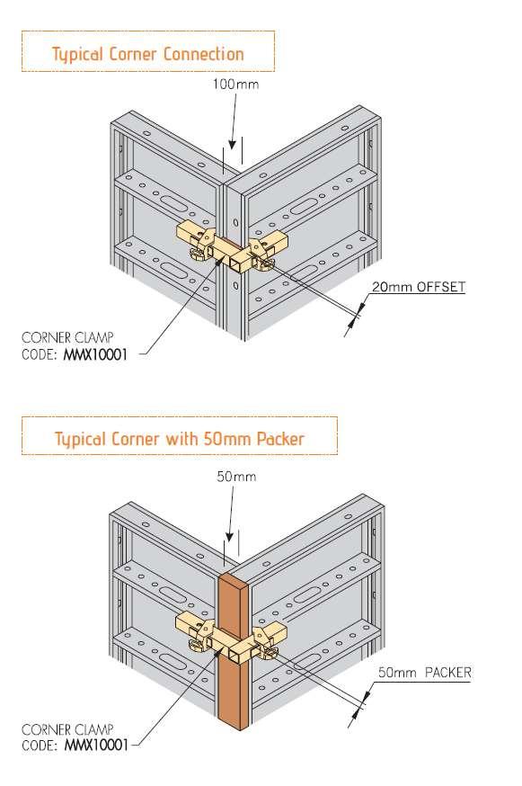
38 Minima Minima Aligning Panel Clamp The Aligning Panel Clamp tightly closes and aligns the butt joints of the panels without offset in a single cycle. MMX10003 Minima Aligning Panel Clamp 3.36 Note: SWL = 8kN in any direction in the plane of the clamp Corner Clamp The Corner Clamp makes an outer corner out of two standard panels MMX10001 Minima Outer Corner Clamp 6.61 Note: SWL = 8kN in any direction in the plane of the clamp Crane Hook Crane Hooks are used for lifting either single panels or panels assembled into larger shutters. Two Minima Crane Hooks are used at all times. MMX10021 Minima Crane Hook 7.47 Note: SWL = 500kg Edge Tie Bearing Used to connect stop end formwork. Can also be used to tie across the top of the formwork panels, reduction the need for some consumables. MMX10023 Minima Edge Tie Bearing 2.28 Note: SWL = 12.5kN Minima Access Bracket Connects to Minima Panels and combined with Minima s guardrail post and Ultraguard edge protection system to provide safe access at height. MMX10006 Minima Access Bracket 9.73 Note: SWL = 5.0kN evenly distributed, includes self-weight and boards. 38

39 Minima Guardrail Post Connects to Minima access bracket to provide safe access at height. MMX10007 Minima Guardrail Post 4.26 Minima Minima Waler Components Used together to aid alignment and provide additional strength to the Minima system. MMX10008 Minima Waler MMX10010 Minima Waler Tie 300mm 0.71 MMX10022 Minima Waler Plate 220 (AZ tie nut 230) 2.37 MMX10009 Minima Multi-purpose Waler MMX10031 Minima Waler Tie BTX10021 Standard Waler Plate 1.35 MMX10031 BTX10021 MMX10022 MMX10009 Ground Plate Used to anchor the formwork and prevent uplift during the concrete pour. MXX10012 Maxima Ground Plate 0.7 MXJ10012 Maxima Ground Plate 50x16x120mm


40 Minima Centre Tensioning Bolts Combines Minima Panels in a tension resistant joint via the hole grid of edge profiles. MMX10014 MMX10012 Minima Tension Bolt MMX10014 Minima MP Bolt 0.60 MMX10011 Minima Tension Nut 0.64 MMX10015 Minima Multi Purpose Nut 0.46 MMX10015 MMX10012 Minima Prop Clamp Connector Clamps alignment props to Mimina panels MMJ10004 Minima prop clamp connector 0.00 Minima Universal Prop Adaptor Used as the tilt base for Push Pull props MMM20006 Minima Universal Prop Adaptor Minima R Strut Connector Connects to RMD table props as inclined struts to Minima panels. MMX10027 Minima R Strut Connector

41 Push Pull Prop Long Provide alignment to Minima panel with a prop extension range of 1815mm to 5530mm. PRA70001 Push Pull Prop Long PRA70015 Push Pull Prop Short Minima Note - Extension range of 1815mm to 5530mm Minima Panels Technical Information Maximum allowable pressure Walls Maximum allowable pressure Columns Maximum tie load on an individual edge section Edge profile, Maximum load in tension Rib profile, Maximum load normal to ply face = 60kN/m2 = 90kN/m2 = 40kN = 8kN = 12kN Minima Accessories Technical Information Minima Waler Tie 300 When engaged in a hole in the panel rib (Rib limits) =12kN For all other applications = 19kN Minima Clamps (MMX10001, MMX10002, MMX10003, MMX10028) In every direction =8kN Minima Tension Bolt (Edge profile limits) =8kN Minima MP Bolt and Nut Minima MP Panel 2700 = 22.2kN Minima MP Panel 1800 = 15.4kN Minima Access Bracket UDL including self weight of boards = 5kN Minima Alignment Prop Medium and Short = 8kN Minima Crane Hook = 500kh Minima Panel Connections Panels are connected by either the Minima Wedge or the Minima Adjustable Clamp. Clamping occurs at the panel edges. All clamps should be located over a panel rib. If the clamps on the vertical joints are not fixed across the horizontal ribs, the alignment of the panels is likely to be compromised. Generally two clamps are required at each vertical joint of each panel and one Adjustable Clamp at each horizontal joint of each panel. 41
42 Minima When different height panels are clamped side by side, ribs may not line up causing a rib offset. The Adjustable Clamp is capable of clamping across ribs with a maximum 54mm offset. The Minima clamp is capable of clamping across ribs with a maximum 30mm offset. 42
43 Minima Note: It is good practice to place the smaller panels at the bottom of the shutter. Tie requirements or mating panels may influence this arrangement. Minima Panels orientated horizontally for low wallforms do not provide sufficient space for Maxima Rapid Tie Plate and Rapid Tie Bar at the bottom tie positions. For these applications a Minima Horizontal Ground Plate and Nut Hexagon shall be used. The Minima forms can be extended in height by placing a panel horizontally. For specific length extension up to 400mm, a ply and timber make up can be used. No ties are required at the very top of the formwork provided that Minima Adjustable Clamps are used at a maximum of 900mm centres to join the top to the lower panels. The bottom of each Adjustable Clamp catches either a vertical or a horizontal rib. 43
44 Minima 44
45 Minima Panel Infill Connections To construct a specific form length, timber infills may be required. Use a timber and ply make up to suit a panel depth of 120mm and tie with the following arrangements: IMPORTANT: When packer exceeds 50mm thick, Waler Tie Nut 230 must be used. Minima Infills up to 50mm Use the Minima Clamp (MMX10003) and a Standard Wing Nut and Flat Bracket tied through the timber. Infills 50mm to 150mm Use the Minima Adjustable Clamp (MMX10002) and a Waler Tie Nut tied through the timber. (Minima Waler Plate) 45
46 Minima Infills 150mm to 300mm Use the Waler 80 fastened to the rib of the Minima Panel using two Waler Tie 300s. A tie is required through the infill. See the arrangement below. Minima Corner Details Corner clamps have an integral 20mm packer to create a 100mm overlap with the 120 deep panels. The corner clamp can be secured to the panel in two locations to permit a 50mm packer to be introduced. The Adjustable Clamps should be positioned over a panel rib. For walls higher than 2700mm, the Minima Panel make-up should always include a 2700mm high panel on the bottom. For walls greater than 4200mm, two No panels are required at the bottom. 46
47 Minima 47
48 Minima Minima Access The Minima Walkway Bracket can be connected to both vertically and horizontally orientated Minima panels. In both cases, the Walkway Bracket is attached to the panel rib and is fixed at the closest position to top of shutter. Hand rails are constructed using tube and fittings. When the panel is orientated vertically, the two pins at the end of the Walkway Bracket locate in holes along the panel rib. Two R'-Clips are used to secure the Walkway Bracket to the rib. When the panel is orientated horizontally the twin angles at the end of the Minima Walkway Bracket locate around the rib and a Superslim Connecting Pin is used to secure the Walkway Bracket to the rib. When the panel is orientated vertically, the Minima Walkway Bracket is connected to the panel rib. The two pins locate in holes along the panel rib. Two R clips are used to secure the Walkway to the rib. When the panel is orientated horizontally, the Minima Walkway Bracket is connected to the panel rib. The twin angles locate around the rib. A Superslim Connecting Pin is used to secure the Walkway to the rib. 48
49 Scaffold board can be arranged 4 planks wide, however, planks may require notching at handrail post locations. Secure the planks to the Walkway Bracket by nailing them to the timber insert on the Walkway Bracket. When using planks, brackets are not to be more thank 1800mm apart. Plans may be lapped when necessary. Minima When edge protection is required without a walkway, a tube and fitting arrangement can be applied to the panel. A single coupler is bolted to the rib pressing with an M16 bolt & nut. The M16 bolt must have a low profile head or machined head to stay clear of the scaffold tube. A washer must be used under the nut to reduce damage to the rib. 49
50 Minima Minima Medium & Short Alignment Prop The Minima Alignment Prop aligns and secures single Minima Panels up to a height of 2700mm. The prop comes completely assembled, including clamps, props and a base unit. The props are usually clamped to the edge profiles of the panel joints unless special arrangements are required. If propping must occur at the end panel, a timber packer is required. 50

51 Minima Crane Hook The Minima Crane Hooks are used for lifting either single Minima panels, or Minima panels assembled into larger shutters. Two Minima Crane Hooks are used at all times. The Minima Crane Hook is engaged around either the top edge of the vertical panel or side edge of the horizontal panel. The hook is always be located around a vertical rib, or ribs. The captive pin nee Minima ds to be fully engaged through the holes in the panel ribs before a sling is attached. A pair of suitable slings shall be attached to the links on the two Crane Hooks. The slings shall be of a length that ensures that the maximum angle of spread between the two slings is


 PSX10005 Paraslim Porthole Bearing 55kN PSX10003 MNX10099 PSX10021 Paraslim Bracket 35 deg Cast Weld Paraslim Bracket")
52 M Paraslim PARASLIM Deck Edge Formwork System Paraslim is a modular formwork system for use in the construction of bridge deck cantilevers. The system allows formwork to be erected and dismantled quickly either piecemeal or in panels. Modules of Paraslim are prefabricated on the ground before being crane handled into position. Key Features & Benefits: All erection, adjustment and stripping operations are carried out safely from deck level, without the need for access systems. Fully adjustable to fit a wide range of steel or concrete bridge beams and sheet piles Working platform and handrail immediately in place Inclined soffits readily accommodated Paraslim Member Capacities Allowable Load PSX10002 Paraslim Tie 1500mm kN PSX10007 Paraslim Turnbuckle Forkend & Superslim 45kN &SSU10016 Turnbuckle PSX10010 PSX10009 Paraslim Tube Outer Paraslim Tube Inner 40kN (Tension only) PSX10005 Paraslim Porthole Bearing 55kN PSX10003 MNX10099 PSX10021 Paraslim Bracket 35 deg Cast Weld Paraslim Bracket Paraslim Bracket 50 deg Fabrication kN Tie Angles Code Description Allowable Angle PSX10003 Paraslim bracket 35 deg MNX10099 Paraslim bracket Weld PSX10021 Paraslim bracket 50 deg

 produces consistent and long lasting performance.")
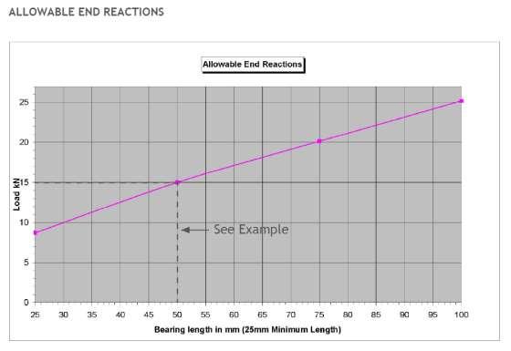
53 GTX BEAMS, CLAMPS AND SPLICES High Productivity; Consistent Performance The GTX beam is a structural laminated veneer timber beam for use as a primary or secondary bearer in a wide range of formwork and falsework applications. The GTX beam is manufactured using 3mm Radiata Pine veneer, individually graded for stiffness, arranged in a predetermined pattern and phenolically bonded for consistent and predictable engineered performance. Key Features & Benefits: Performance: Engineered design to international design standards (AS/NZS 4063, AS 3610 and AS ) produces consistent and long lasting performance. Flexibility: Continuous grooves provide on-site flexibility in positioning and securing formwork to soldiers or primary beams. Efficiency: Engineered profile and direction of wood fibres provide an efficient, cost effective, structural beam. Productivity: Colour flashes to end of beam provides easy identification of length, increasing site productivity. GTX x Beam Properties Gross Area 94cm2 Flexural Rigidity EI 186kNm2 Maximum Bending Moment xx 6.14 knm Max Shear Load 25.8kN Self Weight 5.50kg/m Overall Depth of Section 150mm Overall Width of Section 65mm Maximum reaction on a soldier 35kN Shear Stiffness, GA 3932kN Note: Bearing on the top or bottom faces 6.6N/mm² Refer to Allowable end reaction graph on pg 62. x 53
54 GTX GTX Beams Code Beam Length Colour Weight (kg) GTM10900 GTX Beam (150x65) - 900mm Turquoise 4.95 RAL 5018 GTM11200 GTX Beam (150x65) mm Mauve RAL 4008 GTM11500 GTX Beam (150x65) mm Dark Green RAL 6005 GTX11800 GTX Beam (150x65) mm Brown RAL 8007 GTM12100 GTX Beam (150x65) mm Purple RAL 5022 GTX12400 GTX Beam (150x65) mm Yellow RAL 1018 GTM12700 GTX Beam (150x65) mm Orange RAL 2001 GTJ14201 GTX Beam (150x65) mm Beige RAL 1001 GTX13000 GTX Beam (150x65) mm Light Purple RAL 7045 GTM13300 GTX Beam (150x65) mm Pink RAL 4003 GTX13600 GTX Beam (150x65) mm Rust Orange RAL 3001 GTX14200 GTX Beam (150x65) mm White RAL 9003 GTJ14199 GTX Beam (150x65) mm Bright Green RAL 6018 GTX15400 GTX Beam (150x65) mm Black RAL 9017 GTX26000 GTX Beam (150x65) mm Sky Blue RAL GTX to Soldier Clamp Connects GTX Beams to Superslim Soldiers GTX10001 GTX to Soldier Clamp Mk1A 0.80 Guardrail Post The Guardrail Post is fixed over the GTX Beam and secured with Turbo Screws or 2 qty M12 x 90 Bolts and Nuts. GTM00004 GTX Beam - Guardrail Post


55 GTX Restraint Unit Used in pairs to provide a secure fixing for straight joints and corner applications. GTX10006 GTX Restraint Unit 0.68 M Hook Clamp Used to connect GTX beams to Superslim Soldiers GTJ10002 GTX Hook Clamp 1.00 GTX Swivel Clamp Connects scaffold tube at skew angles to GTX beams GTX GTJ10005 GTX Swivel Clamp 0.25 Saddle Clamp Connects scaffold tube to GTX beams GTJ10006 GTX Saddle Clamp painted 0.22 GTJ90006 GTX Saddle Clamp galvanised 0.22 GTX Wedge Clamp A light duty clamp (similar to the Universal Clamp) with many uses. GTX10002 GTX Wedge Clamp 1.09 Cross Head Spigot Used for insert into the inner tube of the PRJ20400 props PRJ20100 GTX Cross Head Spigot

, Alshor Plus Base 10mm (ASX10011), Rapidshor Base 165mm (RSX10002), Kwikstage Base Jack (KAX20004), or Kwikstage")
56 GTX Outside Corner Bracket Eliminates grout leakage in the corner GTJ10007 GTX Corner Bracket GTX Splice Plate Used to splice two GTX beams together end to end GTJ90007 GTX Splice Plate 1.55 GTX U-Plate A multi-compatible U-head allowing different forms of prop or jack to hold GTX beams. Connections are made with M12 x 30 countersunk bolts with nuts, except to the Kwikstage Base Plate which uses M10 x 30 Bolts and Nuts. GTX10004 GTX U-Plate 1.78 The GTX U-Plate can be fixed to either the Alshor Plus Jack (ASX10012/ASX10030), Alshor Plus Base 10mm (ASX10011), Rapidshor Base 165mm (RSX10002), Kwikstage Base Jack (KAX20004), or Kwikstage Base Plate (KAX20006) and allows the user to run one GTX beam or two (side by side) across the top as primary beams. ASX10012 Alshor Plus Jack ASX10011 Alshor Plus Base RSX10002 Rapidshor Base KAX20006 Kwikstage Base Plate 56

57 GTX Forkhead Cup Spigot Used for the insert into the outer tube of the Airodek props SIJ10030 GTX forkhead cup spigot 4.55 M Plywood 21mm thick laminated plywood sheets PPJ10109 Plywood Sheet Film/F 2500x1250x21mm PPJ10105 Plywood sheet Film/F 2500x625x21mm GTX 57
58 M GTX 58

59 GTX 59
60 GTX 60

61 GTX 61
62 M GTX 62

63 SUPERSLIM The Definitive Formwork Primary Beam The Superslim Soldier is the definitive primary beam for both formwork and shoring applications, with its unrivalled strength-to-weight ratio, versatility and range of accessories. Robust and easily assembled into beams of almost any length, the Superslim Soldier can be re-used on site after site, without modification. Key Features & Benefits: Scope: Ten standard lengths, from 90mm to 3600mm, give almost unlimited scope for assembling beams of virtually any length. Flexibility: Huge range of standard accessories are designed to reflect the diverse applications demanded by major projects. Gantries, shoring, spanning trusses and frames, as well as formwork panels. Compatibility: Standard fixtures and clamps make it fully compatible with other RMD Kwikform product ranges and in many cases, with customers own equipment. Versatility: Formwork ties and other components can be fixed virtually anywhere along the Superslim Soldier s length, giving complete freedom to create the optimum design, whatever the application. Longevity: Robustness to cope with the demands of frequent re-use means easier assembly and consistently accurate fabrication on-site. Superslim 63
 SSX13600 SSX93600 Superslim Soldier 3600mm 72.")


64 Superslim Superslim Soldiers Code Code (Painted) (Galvanised) Description Weight (Kg) SSX13600 SSX93600 Superslim Soldier 3600mm 72.2 SSX12700 SSX92700 Superslim Soldier 2700mm 55.4 SSX11800 SSX91800 Superslim Soldier 1800mm 38.8 SSX10900 SSX90900 Superslim Soldier 900mm 22.0 SSX10720 SSX90720 Superslim Soldier 720mm 18.7 SSX10540 SSX90540 Superslim Soldier 540mm 15.2 SSX10360 SSX90360 Superslim Soldier 360mm 12.0 SSX10090 SSX90090 Superslim Soldier 90mm 7.3 SSX Superslim Soldier End Plate 10mm 2.9 Open ended Soldier Used for captivated wall connections such as Klik Klak platforms SSU10035 Superslim Soldier 360mm O/E


65 Corner Soldier Used to support the inside corners of GTX wall formwork. SSM10900 Superslim Crnr. Soldier 0.9m SSM12700 Superslim Crnr. Soldier 2.7m 64.0 SSM13600 Superslim Crnr. Soldier 3.6m 85.0 Minima Universal Clamp Connects GTX Beams to Superslim Soldiers ALX10001 Universal Clamp 0.75 GTX to Soldier Clamp Used to connect GTX Beams to Superslim Soldiers GTX10001 GTX to Soldier Clamp Mk1A 0.80 Superslim B Clamp Used to connect scaffold tube to Soldiers at right angles RPX10005 B Clamp - Tube to Panel 0.70 C Clamp Used to connect 100 x 50 channels walers to Soldiers at right angles. RPX10006 C Clamp - RSJ to Panel Way Connector Connect to the base of Superslim Soldiers, enabling connections at right angles vertically and horizontally. SSU Way Connector (UK Code SSU20006) SSU Way Double Connector


66 Minima Superslim 100 kn Prop Connector Used to connect Push Pull props to soldiers where a load transfer of more than 65kN is required. SSU10038 Superslim Prop Connector 100kN 7.10 SSJ10038 Superslim Prop Connector 7.10 Anchor Plate 15mm Secures the end of a soldier to concrete or masonry. SSU10036 Superslim Anchor Plate 15mm Corner Angle Allows connection of two soldiers at a right angle, and/or the connection of a heavy duty push-pull prop. SSU10003 Superslim 90 Deg Corner 8.66 Superslim 45 Corner Connects soldiers at 45 SSU10005 Superslim 45 Deg Corner End Angle Waler Plate Used to fasten custom column boxes with a set of ties. SIJ Degree end angle waler plate


67 Corner Pivot Used to attach Soldiers at right angles and permits limited rotation. SSU10019 Superslim Corner Pivot 7.29 SSJ10019 Superslim Corner Pivot 7.29 Minima Pivot Corner 20mm Used to connect Soldiers perpendicular to each other or allow rotation of connected soldiers when used in the second hole position. SSX10037 Superslim Pivot Corner 20mm 4.13 Pivot Cleat Set Used as a hinged connector for Soldiers for angles from 55 to 220 degrees Superslim SSU10028 Superslim Pivot Cleat Set 8.75 SSJ10028 Superslim Pivot Cleat Set 8.75 Prop Spade End Link and Prop Pivot Tube Connects a heavy duty push-prop to the porthole of another Soldier. SSU10012 Prop Spade End Link 3.09 SSU10004 Prop Pivot Tube Black 1.81 SSJ11012 Prop Spade End Link 3.09 SSJ10012 Plate Assembly 12mmx225x SSJ11004 Prop Pivot Tube Black 1.81 SSU10004 SSU10012 SWL = 65kN (SWL can be restricted by the length of the push-pull prop). 67

68 Minima Superslim Prop Tube End Link Used to connect Superslim Push Pull props to Megashor shafts SSU10013 Prop Tube End Link 2.88 SSX10051 Short Tube End Link - Prop 1.77 SSX10051 R Clip SSX10046 Superslim 19mm Pin and R Clip 0.28 SSX mm R Clip 0.01 SSU10011 R Clip 5 x 100mm 0.03 SSX10046 SSX10045 Tilt Plate Used to connect a push-pull prop to a plane surface at any angle. SSU10034 Superslim Tilt Plate 4.89 SSJ10134 Superslim Tilt Plate 4.90 SSU10011 Tilt Plate/Double Prop Foot Used to connect a push-pull prop to a plane surface at any angle. SSJ10034 Tilt Plate/Double Prop Foot 3.00 Superslim Left Hand and Right Hand Prop Jacks The prop jacks are used to create a heavy duty taking shoring and alignment props, which connect to backing members of formwork. SSU10007 Superslim Prop Jack L.H. (green) SSU10008 Superslim Prop Jack R.H. (red) Adjustable Range for Jacks = mm SWL = +/- 100kN 68


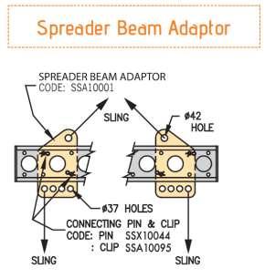
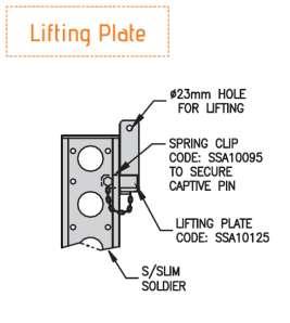
69 Superslim Soldier Jack Used to level formwork in a horizontal and vertical application, with a working range of 115mm closed to 400mm fully open. SSU10027 Soldier Jack 170mm 5.00 AWL 20kN Vertically Fully Open AWL 25kN Horizontally Fully Open AWL 170mm from back of Soldier Lifting Plate For attaching lifting equipment to Superslim Soldier shutters. SSU10032 Lifting Plate 15kN 3.19 SWL = 15kN vertical SWL = 7.5kN horizontal Superslim Spreader Beam Plate Used with Superslim Soldiers to construct lifting beams. SSU10015 Spreader Beam Adaptor Assembly 7.30 SSX10052 Spreader Beam Adaptor Assembly Klik Klak Wall Bracket and Latch Used in conjunction with Superslim 360 Open End (SSU10035) to create crane lifted platform applications. SSU10037 SSU10030 Klik Klak Wall Bracket 6.72 SSJ10030 Klik Klak Wall Bracket 6.72 SSU10037 Klik Klak Latch 3.92 SSJ10037 Klik Klak Latch 3.92 SSU


70 Superslim Rocking Head Used to attach beams onto soldier props SSU10023 Rocking Head 36mm 4.31 Adjustable base Used to provide base adjustment and spread loads SSU10025 Superslim Adj Base mm Roller Adaptor Plate Used to adapt the bolt holes from the Soldiers to connect to a Hillmann Standard Roller SSJ10005 Roller Adaptor Plate 1.97 Turnbuckles Turnbuckles are used to prop, align and adjust Superslim Soldiers and Walers. SSU10016 Turnbuckle Joint Stiffeners Increases the tension and bending capabilities of a joint between Superslim Soldiers SSJ93601 Joint Stiffener 32x SWL tension = 150kN SWL bending = 20kNm 70


71 Access Bracket Used to support a three board wide access platform. Has integral spigot to accept standard scaffold tube for tube guardrails or Ultraguard mesh barrier. SSU10031 Superslim Access Bracket 6.65 Minima Porthole Bearing Enables connection of a Rapid Bar Tie to a porthole at any angle. SSX10039 Porthole Bearing 20.8mm diameter hole 1.22 BTX10017 Nut - Hexagon 50mm 0.16 Hillman Standard Roller A load bearing roller used typically in a traveller system. Superslim SSJ10003 Hillman Std Roller 20-OT SSJ10004 Preload Pad for 20-OT Std Roller 2.00 Top Pivot Used in conjunction with the Lower Pivot and bolted to the vertical soldiers SSB70003 Top pivot Lower Pivot Used in conjunction with the Top Pivot and bolted to the horizontal soldiers. By rotating the adjustment screw, the mechanism is able to be adjusted horizontally. SSB70006 Lower pivot
72 Superslim The Superslim Soldier The Superslim Soldier has different sectional properties about its main axes because of its cross sectional shape and shall not be used in any application which will induce bending about the weaker axis (yy axis) EI xx value = 4020 x 10⁹ Nmm² GA value = 17350kN Maximum Working Load Limit in bending = 29.9kNm (LSCF = 1.5) Maximum Working Load Limit in bending at joint 4 off M16 G8.8 bolts = 12kNm (LSCF = 1.5) 6 off M16 G8.8 bolts = 18kNm (LSCF = 1.5) Maximum Working Load Limit in bending at joint with a 6 way connector = 12kNm (LSCF = 1.5) (connected to 10mm End Plates) Maximum Working Load Limit at tie position = 75kN (LSCF = 1.5) Maximum Working Load Limit in tension with 2 Superslim Soldiers bolted together With either 1 off M24 G8.8 bolt or 4 off M16 G8.8 bolts = 100kN (LSCF = 1.5) 6 off M16 G8.8 bolts = 150kN (LSCF = 1.5) Maximum Working Load Limit in compression of a Superslim Soldier without Jacks = 100kN Maximum reaction on Superslim Soldier = 75kN (min bearing length 100mm) Maximum Allowable Load transferred from Superslim 90 to Lower Superslim Soldier = 65kN Maximum shear on Superslim Soldier = 130kN Notes (1) Maximum Working Load Limit in bending is based on the compression flange being laterally restrained at 2500mm centres, maximum. (2) Maximum tie load (75kN) may be increased by using Hi-Load Waler Plates Material used in the Superslim Soldier C pressings for a minimum yield of 400MPa. Superslim Soldiers shall not be used to span distances greater than 2500mm without lateral restraints. These restraints can normally be tubes connected to the Soldier by Bracing Connectors. Superslim Soldiers shall not be used at header beams with Trishore or Seniorshore as the supports. 72
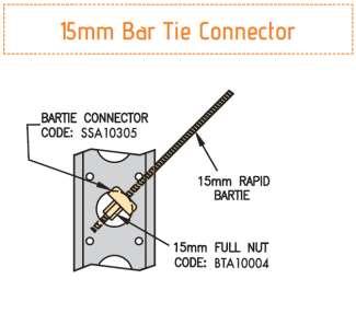
73 Superslim Soldier Accessories Walkway Base, cantilevered out from Superslim Soldier Maximum Working Load Limit = 6.2kN UDL (LSCF = 2.0) Walkway Base, supported by a turnbuckle from a Superslim Soldier Maximum Working Load Limit = 20kN UDL (LSCF = 2.0) Plumbing Jack Maximum Working Load Limit = 37kN UDL (LSCF = 1.5) Bar Tie Connector Maximum Working Load Limit = 66kN Connecting Angle In compression or tension Maximum Working Load Limit = 45kN (LSCF = 1.5) Hinge Assembly At any angle (see details) Maximum Working Load Limit In tension or compression = 76kN (LSCF = 1.5) Spreader Beam Adaptor Maximum Safe Working Load = 55kN Wheel Assembly 150mm Maximum Safe Working Load = 612kgs Wheel Assembly 250mm Maximum Safe Working Load = 1800kgs Superslim Notes (1) Bar Tie Connector is restricted by the capacity of the Superslim Soldier C pressing (2) The capacity of the Spreader Beam Adaptor varies depending upon the length of the beam and the angle of the main slings (3) Rating of Wheel Assemblies is based on travelling speed not exceeding 5km/hr when moving on a smooth surface, free from obstructions 73

74 Superslim Connection Details SSX10046 SSX
75 Punchings and Geometry Superslim Minima Note The arrangement of holes in the end plates of hire fleet soldiers vary. If using soldiers bolted to Megashor please specify 7 hole end plate soldiers. 75
76 Superslim Superslim Joint Stiffeners Used to enhance the load bearing characteristics of a Soldier joint. Maximum Allowable Tensile Load 150kN Maximum Allowable Joint Bending Moment 20kNm Superslim Lifting Plate 15kN Used in pairs for lifting formwork panels up to 30kN. For combined stress checks refer to RMD Kwikform Technical Office. Allowable Working Load on arrow A 15 kn Allowable Working Load on arrow B 7.5 kn Superslim Access Bracket Used to support a three board wide access platform. Has integral spigot to accept standard scaffold tube for tube guardrails or Ultraguard mesh barrier. 76
77 Superslim Turnbuckle & Superslim Plumbing Foot Used in single sided base formwork Allowable Working Load in the Turnbuckle ± 45kN B Clamp Used to connect scaffold tube to Soldiers at right angles. Superslim Note: When pairs of B clamps are used on a tube to soldier connection an allowable working load of 3.25kN may be used in any direction. Half Coupler Used in pairs to connect scaffold tubes to the end plates of Soldiers. E.g. to create hand rail posts etc. Allowable Working Load per coupler 6.25kN slip along tube 10kN direct tension 77
78 Superslim Universal Clamp A light duty clamp with many uses. AWL Tension = 3kN per clamp AWL Slip = 1kN per Pair of clamps Note: The clamp is to be fixed hand tight plus 1/4 turn. Flange to Flange Wedge Clamp A wedge fixed clamp that enables aluminium beams to be clamped to Soldiers at 90 degrees in static soffit applications. AWL Slip = 1kN per pair of clamps Waler Plate Heavy Duty Used with 15mm diameter Rapid Bar Tie and accessories. Allowable Tie Load 90kN when used with Superslim Soldiers. 110kN when used with special steel channels. 78
79 Waler Plate Angle 3/4 Used with 15mm diameter Rapid Bar Tie and accessories where the tie is not perpendicular to the Soldier. Waler Plate Hi-Load Used with 20mm diameter Rapid Bar Tie and accessories. Superslim Porthole Bearing Enables connection of a tie rod to a Porthole at any angle. 79
80 Superslim Superslim Adjustable Base Used to provide base adjustment and spread load. Allowable Working Load 150kN, 100kN if load is to be removed by rotation of the jack handle. Not to be used in tension. The maximum load that can be applied by rotating the jack handle is 40kN using a scaffold tube extension when the threads have been well greased. Superslim Corner Pivot Used to attach Soldiers at right angles and permits limited rotation. 80
81 Prop Spade End Link & Prop Pivot Tube Used to attach Push Pull Props to Soldiers. Minima Superslim Prop Connector 100kN Used to connect Push Pull Props to Soldiers where a load transfer of more than 65kN is required. Superslim 81
82 Minima Superslim Superslim Prop Tube End Link Used to connect Super Slim Push Pull Props to Megashor shafts. Superslim Prop Jacks Used in pairs to provide length adjustment to Push Pull Props. Superslim Tilt Plate Used to connect a Push Pull Prop to a plane surface at any angle. 82
83 Superslim 90 Degree Corner Used to connect Soldiers at right angles and/or enable connection of a Push Pull Prop. Superslim Pivot Cleat Set Superslim 83


84 Minima Superslim Superslim 45 Deg Corner Connects Soldiers at 45 degrees. Maximum allowable bending moment = 12kNm Connect using 8 No. M16 x 40 Set Pin gr8.8 and 4 No. M16 Nut gr8 BZP and 2 No. M16 Round Washer BZP (BNU 16007, BNU16001 & BNU16002). Superslim Pivot Corner 20mm Used to connect Soldiers perpendicular to each other or allows rotation of connected soldier when used in the second hole position. 84
85 6-Way Connectors in use The Six Way Connector allows Soldiers to be connected at node, and provides an effective component in making up frame structures with Superslim Soldiers. For particular high concentrations of leg loads a twin 6 Way Connector is also available. The allowable bending moment at the connector is dependent upon the direction of the axes of the applied load. The values below have derived from test results using a factor of safety of 1.8. The allowable bending moment at the connector is dependent upon the direction of the axes of the applied load. The values below have derived from test results using a factor of safety of 1.8. Moment about x-x axis (strong way) on sides 7.6kNm Moment about x-x axis on top or bottom 4.4kNm Moment about y-y axis on top, bottom or sides 3.6kNm Superslim 85
86 Minima Superslim Superslim Anchor Plate 15mm Used for anchoring the ends of Soldiers to concrete or masonry. Applications include: Single sided formwork Base formwork with or without turnbuckle and plumbing foot (SSU10016 & SSU10033) Battered formwork in combination with pivot cleat set (SSU10028) Connecting Megashor props to abutment walls Base plates in façade retention schemes (use stacked in pairs for increased capacity). 86
87 Superslim Klik-Klak Latch Used in conjunction with (post 2002) Superslim Soldier 360mm Open End (SSU10035) to create crane lifted platform applications. Superslim Klik-Klak Wall Bracket Used wall mounted to support Klik-Klak Latch. Superslim Note: The Superslim soldier length must be between 230 & 265mm shorter than the wall gap to ensure the unit cannot become disconnected at one end of the platform during use. Check adequate bearing of latches after each lift and wedge gaps between the wall and the end of the Superslim tight both ends. 87
88 Superslim Klik-Klak Wall Pocket Used as an alternative to the klik-klak wall bracket when forms cannot be retracted sufficiently to bolt the bracket onto the wall prior to lifting. Note! The Superslim soldier length must be between 40 & 100mm shorter than the wall gap to ensure the unit cannot become disconnected at one end of the platform during use. Check adequate bearing of latches after each lift and wedge gaps between the wall and the end of the Superslim tight both ends. Lifting - Spreader Beam Adaptor Assembly Used in pairs with a Superslim Soldier to make an economical spreader beam for lifting loads of up to 9 tonnes. Includes top and bottom shackles ready for connection to customers slings and lifting equipment. Each Spreader Beam Adaptor Assembly comprises:- 1No Spreader Beam Adaptor, 4No Superslim 19mm pin & R Clip & 2No Shackles Each spreader beam plate fits into the web of the Soldier and allows for 55mm adjustment in lifting length. The maximum dimension between lifting points on a unit is 3060mm when using a single 3600mm Soldier. The spreader beam plate has been designed in accordance with The Construction (Lifting Operations) Regulations The plates are available on purchase only and each plate is individually numbered and tested to twice working load and stamped. A certificate of testing is available from RMD Kwikform on request. A table of maximum lifted load related to the internal angle of the slings is given in the graph on page The user will need to supply the correct two legged chains or slings. 88

89 Lifting Spreader Beams Use the Spreader Beam Adapter only in the orientation shown with the row of four holes positioned at the bottom of the unit. Ensure that the lower slings are vertical by moving the position of the unit along the Superslim, fine adjustment is afforded by moving the lower shackle between the four hole positions. Never use less than four 19mm pins and clips to connect the unit to the Superslim. Where Superslim sections are joined to make longer spreader beams, ensure that soldiers with seven hole end plates are used and connect sections together using 6M16x40 grade 8.8 set pins and nuts torqued to 120Nm. Never use more than three Superslims in the makeup. Do not use with damaged Superslim Soldiers For further instructions on safe use refer to the Equipment Guidance Notes supplied with the equipment or available on request. Superslim 89

90 Superslim Single Sided Formwork When formwork is used on single face applications or where through tie rods are not permitted in the permanent works, the method of restraint of the Formwork requires careful examination for each application. Generally on pours up to about 2.7 metres high a solution is to use inclined props as shown in Fig WS1. The arrangement will require vertical restraint for the uplift forces and are suitable anchorage into the base slab. One solution is to use Anchor Plates SSU10036 at the base of each soldier with prop bolts fixed into the base to resist the loads due to both horizontal concrete pressure and uplift. In all applications of single face formwork the concrete pressure should be kept to a minimum. The use of Soldiers as backing members to cantilever construction in single face, such as on climbing formwork requires particular care. A typical example is shown at figure WS2. The limiting condition is the tip deflection of the Soldier and the arrangements shown below limit the deflection to 5mm. The pour height is limited to approximately 1.5 metres. It is possible to preset the top inwards by using the Soldier Jacks. It is recommended that the length of tail of the Soldier is similar to that of the pour height. For longer lengths of vertical Cantilever refer to an RMD Kwikform Technical Office. Single faced wall up to 2.7m high Single faced climbing form 90


91 SHORING SYSTEMS ALSHOR PLUS Next Generation Aluminium Shoring Alshor Plus is the next generation of a proven aluminium shoring system with increased loading of up to 120kN/leg. This fixed at the head support system provides a high performance, modern aluminium shoring system, with increased safety features, improved on-site versatility and greater cost effectiveness. Key Features & Benefits: Lightweight: Ease and speed of use compared with traditional shoring systems. 120kN Leg Load: The increased leg load reduces the need for additional support equipment for most loading conditions, reducing erection and strike times. Propping Range: The high legload capacity also provides an increased propping range providing greater versatility in both high and low support levels. Unique Connections: Unique blade and pocket connection enables Frames and other accessories to be located onto legs quickly and easily. Jack Extension: The increased extension range of the Alshor Plus Jack makes it quick and easy to obtain the exact soffit height. Quick Strike: The Jack s unique quick strike facility provides quick release of the load for easy disassembly. Integrated System: Alshor Plus is designed to minimise the number of loose parts to dramatically improve assembly and disassembly speed. Alshor Plus 91


92 M Alshor Plus Legs Used to carry the loads to the foundation. Safe working loads in compression depend on restraint conditions. A Spigot is used to locate Alshor Plus legs end to end. When the joints are put into tension, an Alshor Pin is used to secure the leg components. ASJ30500 Alshor Plus Leg 500mm 2.50 ASX31500 Alshor Plus Leg 1500mm 7.33 ASX32000 Alshor Plus Leg 2000mm 9.60 ASX32500 Alshor Plus Leg 2500mm ASX33000 Alshor Plus Leg 3000mm ASX34000 Alshor Plus Leg 4000mm ASX10013 Alshor Plus Spigot 6mm 2.46 Leg Tripod Used to stabilise Alshor Plus props up to 5,25m long in vertical falsework application without brace frames and founded on a level surface. ASJ10060 Leg Tripod ASX10060 Alshor Leg Tripod


93 Jacks The Short Jack should only be used at the top of the shoring system to support horizontal primary bearers. The Jack is locked to the leg by the spring loaded plunger. The Long Jack incorporates a quick release mechanism which shortens the jack by 12mm with a single hammer blow to the Quick Release Collar. The unique swivel base plate on the long jack allows a combination of 10 and 2.5 of rotation. ASX10030 Alshor Plus Jack Short mm 11.0 ASX10012 Alshor Plus Jack Long mm 17.2 U-Plate The U-Plate 6mm bolts onto the short jack when a U-Head is required with adjustment. The U-Plate 6mm is fixed using 2qty M12 x 40mm Counter sunk bolts and nuts. ASX10023 U Plate 270x220x6mm 3.94 BNJ12001 Bolt - M12 x U-Head The U-Head incorporates a spigot that locates inside the Alshor Plus leg. It is fixed by a spring retainer that locates in the cross drilled holes at the end of the leg. Alshor Plus ASX10015 U Head 220w x 10mm 6.58 Note: Alshor Plus Straight Pin 16mm (ASX10020) must be used in tension applications AWL in tension with straight pin is 12kN. Alshor Superslim Clamp The Alshor Superslim Clamp is used to connect a Superslim primary beam to an Alshor Plus U-Head ASX10056 Alshor Superslim Clamp


94 Alshor Plus Base Plate The Base Plate can be used at the base when adjustment is not required or at the top when a U-Head is not required. ASX10011 Base Plate 200 x 170 x 10mm 3.50 Bracing Frames The Bracing Frames incorporate spring loaded latches which automatically lock under the lugs on the legs. At the ends of the top and bottom frame members are steel locating tongues that engage in the leg lugs. ASX41200 Alshor Plus Frame 1200mm 8.91 ASX41800 Alshor Plus Frame 1800mm ASX42400 Alshor Plus Frame 2400mm ASX4300 Alshor Plus Frame 3000mm Straight Pin Used to connect leg components in tension applications. ASX10020 Alshor Plus Straight Pin 16mm 0.11 Note: The Alshor Spring Retainer does not need to be removed from the spigot when the straight pin is used. 94
 Locate in the lug extrusions with integral spring latches to provide guardrails. The tubes are painted orange to aid visual checks. ASX71200 Alshor Plus Guardrail 1200mm 3.")

95 Jack Spanner Used to adjust jack extensions on built tables. Not designed to release loads. ASX10029 Jack Spanner 4.79 Guardrails (Handrails) Locate in the lug extrusions with integral spring latches to provide guardrails. The tubes are painted orange to aid visual checks. ASX71200 Alshor Plus Guardrail 1200mm 3.08 ASX71800 Alshor Plus Guardrail 1800mm 4.08 ASX72400 Alshor Plus Guardrail 2400mm 5.08 ASX73000 Alshor Plus Guardrail 3000mm 6.08 Note: Not to be used as supports to board bearers. Board Bearers Board bearers locate over the top chords of bracing frames or ledgers enabling the support of scaffold boards. Positioned at 1200mm centres or less. ASX61800 Alshor Plus Board Bearer 1800mm 7.97 Castor Unit Used to transport Alshor Plus tables on a smooth level surface. The Castor Unit slips over and positively locates onto the bottom of the Alshor Plus long or short Jack. Alshor Plus ASX10038 Alshor Plus Castor Unit ASX10039 Alshor Plus Castor Unit Handle 8.39 Note: Maximum loading = 800kg; Minimum allowable Jack extension = 350m 95

96 Alshor Plus Height Twin pronged C-Hook Lifting equipment used for crane handling complete Alshor Plus tables of up to 4000kg and up to 7,2m long. ASX10067 Twin Pronged Table C-Hook Note: Please refer to Equipment Guidance Note UIX10606 for information regarding safe use. Alshor Plus Leg Range Leg Make-Up Ensure that the Jack-end of the structure bears against a foundation that is restrained against rotation. E.g. a concrete slab or railway sleepers haunched with concrete. Erect props within 1.5 degrees of plumb. 96
97 Connection Details A Spigot is used to locate Alshor Leg Plus legs end to end. When the joint is in tension (ie. lifting), Alshor Pins are used to connect the leg components together. The Safe Working Load of this arrangement is 40kN. Jacks There are two Jacks in the Alshor Plus range, a Long Jack which has a range of mm and a Short Jack that has a range of mm. Both Jacks are constructed from the same hollow aluminium extrusion which nests closely inside the Alshor Plus Leg and prevents the Jack from turning. The cut thread is self-cleaning with a four start thread to permit the nut to move 25mm in one turn. A tape measure is set into one of the several grooves in the profile. Long Jack This Jack incorporates a quick release mechanism which shortens the Jack by 12mm with a single hammer blow to the Quick Release Collar. Alshor Plus The Base Plate incorporates a spherical seating that engages around the base of the Jack and permits the Base Plate to rotate. This feature ensures that the leg is concentrically loaded. 97
98 Alshor Plus Load Release Mechanism Used to shorten the Alshor Plus Jack by 12mm with a single hammer blow in order to release loads of up to 120kN from the Alshor Plus Legs. Activate by lifting the locking spring plunger and striking the release collar. Refer to Equipment Guidance Notes UIX10203 for further details of operation. Jack Spanner Used for adjusting jack extensions on built tables. Not designed for releasing load. Short Jack This Jack should only be used at the top of the shoring system to support horizontal primary bearers. The Jack is locked to the Leg by the spring loaded plunger. Jack mm (ASX10030) weight 9.80kg A jack without a load release mechanism most commonly for use at the head in flat soffit applications or in backpropping applications. AWL is 120kN max. 98

99 U-Plate Used attached to the Long or Short Jack or the Plain Base/Head M Bracing Frames These frames incorporate spring loaded latches which automatically lock under the lugs on the Legs. At the end of the top and bottom frame members are steel locating tongues that engage in the Leg lugs. Installation is facilitated by the lower tongues being longer than the upper lugs and these incorporate a step to allow the lower tongues to be partially engaged first. Used to space the Legs apart and laterally restrain them. Also used to support access components. Frames are rigid, lightweight and easy to install. Spring latches give positive location beneath the lug extrusion with a single action. The lower frame tongues are 25mm longer than the upper ones and stepped in their width to further aid and speed installation. Alshor Plus 99

 Board Bearers Locate over the top chords of frames or ledgers enabling the support of RMDK scaffold")
100 Alshor Plus Handrails Locate in the lug extrusions with integral spring latches to provide guardrails. Not to be used as supports to board bearers. Tube painted orange to aid visual checks. Designed to comply with the loading and deflection requirements of BS1139 Part 5 (5.4) Board Bearers Locate over the top chords of frames or ledgers enabling the support of RMDK scaffold boards at a maximum of 1200mm. 100


101 Alshor Plus Leg Tripod Used to stabilise Alshor Plus props up to 5.25m long in vertical falsework applications without brace frames and founded on a level surface. Fit tripods to the props supporting each end of primary beams up to 4.8m long and at maximum of 4.8m centres for longer beams. Ensure that the heads of all props are clipped to the primary beams. Folds flat for storage rotate each leg and lock in place with the built in anti-kick lock mechanism. Position around the prop and secure with the built-in stem-lock tightening lightly with a hammer. Fits all sizes of tube prop between 48.3mm and 0mm diameter. When used with Alshor Plus the minimum jack extension is 700mm. Adjustable Pocket Assembly Used alone the Adjustable Pocket enables a frame, ledger or guardrail to be connected to an Alshor Plus leg at a level between the pocket extrusions. AWL 6.25kN (does not resist uplift) Alshor Plus 101

102 Alshor Plus Castor Unit Used to transport Alshor Plus tables. The Castor Unit slips over and positively locates onto the bottom of the Alshor Plus Long or Short Jack. Rated for a Maximum Load of 800kg. When tables are designed for moving using this product the minimum base jack extension is 350mm. The castor unit has solid tyres as standard. Pneumatic tyres are available as an option and are useful when travelling tables over soft ground with tyres inflated to a low pressure. Pneumatic tyres are also useful when heavy tables require the use of more than 4 castor units. In such cases inflate the tyres to full pressure and adjust the base jacks after installing the wheels to equalise compression of tyres and wheel loading. The overall width of the unit is 660mm. Solid wheels are 350mm diameter, pneumatic tyres 400mm diameter. ALSHOR PLUS CASTOR UNIT 1. The maximum load per Castor Unit is 800kg. 2. Ensure the running surface is relatively flat, smooth and clear of obstructions to enable smooth running and even loading. 3. Ensure that the jack baseplate locates over the castor nipples and that the Castor latch is secured around the jack before moving. 4. Ensure that table plan bracing is in-situ as detailed prior to each table move. 5. Extend the handles of Castors not being used for steering and locate in the Alshor Plus leg pocket extrusions. 6. Take appropriate measures to avoid tables running away on slopes or running beyond slab edges. 7. Do not allow personnel to ride on Castor Units. 102
. There is no need to remove the spring retainer.")
103 Alshor Superslim Clamp Used to secure Superslim primary beams to Alshor Plus falsework AWL Tension 5kN U-Head 220w x 10mm Used to support primary beams in flat soffit applications where height adjustment is not required. When incorporated into tables that will be lifted from the soffit add an Alshor Plus Straight Pin 16mm (ASX10020). There is no need to remove the spring retainer. Alshor Plus Base 10mm Used at the base where adjustment is not required or at the head when a U-Head is not required. When used at the head with tables that will be lifted from the soffit add an Alshor Plus Straight Pin 16mm (ASX10020). There is no need to remove the spring retainer. 103


104 MEGASHOR M Ultra Heavy-Duty Shoring Megashor is an ultra heavy-duty propping system designed for axial loads of up to 750kN. However, its real strength lies in its versatility. From heavy support towers to travellers for tunnel formwork, bracing for excavations, shoring and trusses, Megashor can be configured for a huge variety of applications. Key Features & Benefits: Unlimited Options: Eight Leg lengths, ranging from 15mm to 5400mm, plus a full range of accessories means that Megashor can be assembled from standard components into props, towers and trusses of almost any length. Flexibility: RMD Kwikform Superslim Soldiers provide nodal restraint to Megashor legs. This gives ultimate flexibility when planning the sizes of towers and centres of props, therefore minimising the need for custom made equipment. Megashor Unique: A unique 750kN axial load capacity and high axial stiffness ensures that Megashor will accommodate the rigours of heavy duty falsework, cofferdams, bridge bearing replacement and façade retention applications. Limited Disruption: Megashor is approved for support of bridges open to live traffic bridge bearing replacement work can be carried out with minimum disruption to traffic flows. Quality: Our quality assured manufacturing process, using close-tolerance jigs, ensures consistent and accurate fabrication, resulting in good assembly alignment on site, saving time, onsite modifications and labour costs. 104


105 Megashor Legs Code Code (Painted) (Galvanised) Description Weight (Kg) MSX15400 MSX95400 Megashor Leg 5400mm MSX12700 MSX92700 Megashor Leg 2700mm (MSJ12700) MSX11800 MSX91800 Megashor Leg 1800mm MSX Megashor Leg 900mm 64.6 MSX10450 MSX90450 Megashor Leg 450mm 44.6 MSX10270 MSX90270 Megashor Leg 270mm 29.9 MSX10090 MSX90020 Megashor Leg 90mm 21.7 MSX10012 End Plate 9.4 End Plate Used as a pack in Megashor makeups or between Megashor Jacks and Legs to enhance load transfer. MSX10012 End Plate 15mm 9.4 Megashor Screw Jack Used to raise, lower and adjust Megashor leg lengths MSX10011 Megashor Jack 59.0 Range mm 1000kN 105

 that can be removed or relocated to enable controlled raising and lowering of the falsework.")

106 M Megashor Jack Spanner Used to adjust Megashor Jack lengths when applying and removing loads up to 500kN. MSX10022 Megashor Jack Spanner 25.0 Jack Plate Used between Megashor Legs and Megashor Jack for loads over 680kN, or as a spreader plate for a Hydraulic Jack. Also recommended to be used between Megashor Jack and Megashor Rocking Heads. MSX10021 Megashor Jack Plate 26.3 Hydraulic Unit Housing Unit used in conjunction with a hydraulic jack (provided by customer) that can be removed or relocated to enable controlled raising and lowering of the falsework. MSX10017 Megashor Hydraulic Unit Plate Washer Used to stiffen joint connections between Superslim Soldiers and Megashor Legs. BNX20023 Plate Washer x90x15x18 Rocking Head Used for connecting components at an angle to Megashor or in order to eliminate eccentricity or moment transfer at a support or joint. MSX10026 Megashor Rocking Head 180mm 9.4 Important When the rocking head is used to support a header beam the tapped holes must be connected to the Megashor section NOT THE HEADER BEAM. Header Beams should be fully web stiffened adjacent to Rocking Heads. Note: Rocking Heads may be used in either orientation relative to Megashor without reduction in SWL. 106


107 Brace Plates Used to connect braces at the top or bottom of Megashor Towers and to anchor the Megashor structure down to the foundation. MSU10002 Megashor Brace Plate Flat Bracing Purpose made flat bar bracing typically used for bracing between towers and on Megatrusses. Description Flat Bracing 60 x 8mm sales item Flat Bracing 60 x10mm sales item Flat Bracing 80 x 10mm sales item Bracing is custom ordered as a sales order. Please contact your branch for your requirements. Codes include MIJ02344 (Flat Bar Plan Brace 60x8x2344),MIJ10087 (Hammer Head Brace 3135), MIJ10098 (Flat Bar Brace 2781mm long), MIJ10099 (Flat Far Brace 3201mm Long), SIJ90939 (RMD Plan Brace 2806 Long), SIJ90942 (RMD Side Brace 1492 Long), SIJ90947 (RMD Plan Brace 1958 Long) and SIJ90948 (RMD Plan Brace 1611 Long) Packer Plate Used as a pack in Megashor makeups MSJ10013 Packer Plate 15mm 1.0 Megatruss Bearing Plate Used to create an intermediate bearing location along a Megashor shaft. MSJ10015 Megatruss Bearing Plate- 1 MSJ10016 Megatruss Bearing Plate- 2 Megashor Superslim Adaptor Used as an adaptor plate for Megashor to Superslim Code Description Weight MSJ10017 Megashor Superslim Adaptor 9.1 MSJ10015 MSJ10016 Megashor Megashor U Head Used to create a U head on top of a Megashor Shaft MSJ10018 Megashor U Head 107

108 Minima Megashor Torque Wrench Used to torque the M52 Bolts on Megashor Joint Stiffeners MSJ95401 Torque Wrench Socket 30mm Megashor Plan Brace Cleat Used to create a connection point in plan for flat bar bracing. MSU10003 Megashor Plan Brace Cleat 1.46 Megashor Header Beam Used to spread load as a header beam on top of Megashor towers. MSX10009 Megashor Header Beam 950mm MSX10010 Megashor Header Beam 3300mm Megatruss Intermediate Bearer Used in pairs with 650mm Megashor beam to provide a support part way along the bottom boom of a truss. MSX10019 Megatruss Intermediate Bearer Megashor Joint Stiffener Used in pairs to increase the tensile capacity of a joint between Mk2 Megashor sections. MSX10024 Megashor Joint Stiffener 8.40 Megashor Truss Connector Used to make Megashor trusses primarily in façade retention application. MSX10027 Megashor Truss Connector


109 Megatruss End Bearer Used for support at the end of Megatruss MSX10028 Megatruss End Bearer Megatruss Node Used with Mk2 Megashor sections to make Megatruss girders. MSX10030 Megatruss Node Megashor Medium Prop Frame Used to brace 4 Megashor Props together to create a single Mega Prop. MSX10037 Megashor M/Prop Frame (Galv) Megashor Joints Allowable Axial loads in Tension Megashor Note: When 4 M20 x 60 gr. 8.8 bolts are used in the corner holes AWL = 285 kn 109
110 Megashor Megashor Joints Bolting 110
111 Superslim to Megashor Connection Bending & Shear Capacity Superslim Soldiers are attached at node points using twin M16 grade 8.8 fixings. The standard connection consists of 2 no. M16 x 40 grade 8.8 set pins & M16 hexagon nuts. The stiffened connection consists of 2 no. 90 x 90 x 15 plate washers, M16 x 60 bolts and M16 hexagon nuts Megashor 111
112 Megashor Tensile and Compressive Capacity at Node Points In the design of towers with tension bracing fixed to the Megashor legs, horizontal members are in compression. The maximum allowable compressive load applied to a node by a Soldier ledger is 150kN. The forces generated at node points depend upon the configuration of the bracing. The following figures give the allowable loads at the interface of horizontal and vertical members. Compressive loads Tensile loads 112
113 Stiffened connection Megashor Jack mm (MSX10011) weight = 59.0 kg Megashor Loading and Unloading Maximum axial compressive jack loads unloaded by the various methods are as below. A. Unloading 1. Megashor Jack spanner* 500kN 2. Application of sledge hammer to spindle lugs* 650kN 3. Application of sledge hammer to spindle lugs kN * Ensure threads are well greased. + Dismantle jack entirely before use. Clean all four thread surfaces and coat liberally with Molyslip OGL grease prior to reassembly. Details available from RMD Kwikform. Megashor B. Loading By application of a controlled torque via the Megashor Jack Spanner (MSX10022), known loads up to 300kN can be applied. Torque is determined from the graph below or the equation: Tp = 9W where Tp is the Torque applied to the jack handle (Nm) W is the load in the jack (kn) 113
114 Megashor Megashor Jack Spanner Used for applying and removing loads in Megashor Jack (MSX10011). Unloading Megashor Jacks at loads up to 500kN* Controlled application of loads in Megashor Jacks up to 300kN* see Three handle positions allow obstacles to be avoided. * Ensure threads on Megashor Jack are well greased. Megashor End Plate Used as a pack in Megashor makeups or between Megashor Jack (MSX10011) and Megashor to enhance load transfer. 114
115 For loads less than 450kN a plain joint can be used. Used between Megashor shafts and Megashor Jack (MSX10011) for loads over 450 kn or as a spreader plate for a hydraulic jack. Also between Megashor Jacks (MSX10011) and Megashor Rocking Heads (MSX10026) for loads over 800 kn. Megashor 115

116 Megashor Megashor Rocking Head 180mm Used for connecting Megashor or steel components at an angle or in order to eliminate eccentricity or moment transfer at a support or joint. IMPORTANT When the rocking head is used to support a header beam the tapped holes must be connected to the Megashor section NOT THE HEADER BEAM. Header Beams should be fully web stiffened adjacent to Rocking Heads. Note: rocking heads may be used in either orientation relative to Megashor without reduction in AWL. Bolted Connection to Header Beams. Megashor loads are limited to areas within the envelopes below. A - 4 No. M20x60 grade 8.8 Bolts (Shear across bolt thread root) B - 4 No. M20x70 grade 10.9 Bolts (Shear across bolt shaft) C - Welded stop on connected member to resist full shear load e.g. Using 4 No. M20x60 grade 8.8 Bolts, the maximum load capacity in a 30 degree connection is 372 kn read from the graph above. AWL in tension is 250 kn. 116

117 Prop Tube End Link Used to connect Super Slim Push Pull Props to Megashor shafts. Short Prop Tube End Link Used to connect Super Slim Push Pull Props to Megashor shafts when compression loads greater than can be provided by the above item are required. Connection to Megashor leg and Superslim Jack as detailed above Tube End Link Loading Graph Megashor 117
118 Megashor Megashor Lift Point 50kN Used to provide a dedicated lifting point for Megashor structures. Megashor Joint Stiffener Used in pairs to increase the tensile capacity of a joint between Mk2 Megashor sections. Note: in tensile applications all fasteners joining shafts end to end shall be torqued to 300 Nm. 118
119 Megashor M52 Tools Used to tighten M52 gr 8.8 Socket Cap Screws on Megashor MK2 Megatruss Node Used with Mk 2 Megashor sections to make Megatruss girders Megashor Megatruss Node Connections Node to Chords Maximum load transferred between node and Megashor chord P = 744 kn 119
120 Megashor Megatruss Node Connections Node to Diagonals Plain connection AWL = 425 kn tension 750 kn compression Stiffened connection AWL = 800 kn tension 750 kn compression Note: The fasteners connecting the diagonals to the node shall be tightened to a torque of 300Nm. Megatruss Node Connections Node to Cross Brace Enables 15mm diameter Rapid Bar Tie to be connected. 120

121 Megatruss Node Connections Node to Ledger Superslim Soldiers used as ledgers between trusses The capacity of the ledgers should be calculated by reference to the Superslim Soldier technical data. Megashor 121

122 Megashor Megatruss Node Connections Node to Prop/Tie Super Slim Heavy Duty Push Pull Props may be used to prop/tie trusses for loads up to 100 kn*. For loads in excess of this a specially fabricated prop/tie is required, refer to RMD Kwikform Technical Office. Megatruss Node Connections Ledger to Plain Brace Higher Loads Loads up to 100 kn may be carried into a single 21 diameter hole in the Soldier shaft by use of M20 high yield round washers welded to the webs of the Soldier refer to RMD Kwikform for details. The maximum load in the body of a 60 x 8 flat brace is 82 kn. For higher loads use 60 x 10 braces. 122

123 Megatruss End Bearer Used for support at the end of Megatrusses. Megashor 123
124 Megashor Megatruss End Bearer Connections Bottom Chord Supported Truss Megatruss End Bearer Connections Top Chord Supported Truss Note: In all applications there is a need to provide adequate lateral bracing to the end bays of trusses refer to RMD Kwikform Technical Office for details. 124

125 Megatruss Double Chord Connections Chord to Chord Used to transfer shear between main and reinforcing chords. Allowable load transfer P per HSFG bolt: Paint removed and clean 46kN Wire brushed galvanised 32kN Un-wire brushed galvanised 20kN Megatruss Intermediate Bearer AWL = 744 kn per pair of bearers Megashor 125
126 Megashor Megatruss Intermediate Bearer Connections Vertical Applications: Individual Props 126
127 Vertical Applications: Trestles Note: Jack Plates or End Plates are required between Megashor Jacks and Legs at higher loads Megashor 127


128 Megashor Vertical Applications: Towers 128
129 Vertical Applications: Bridge Abutments Megashor Note: Handrailing and toe boards to access omitted for clarity. 129
130 Megashor Inclined Props: 45 Support Note: Jack Plates or End Plates are required between Megashor Jacks and Legs at higher loads 130
131 Inclined Props: Bridge Abutments Megashor 131
132 Megashor Megashor Assembly Guidance 1. Ensure Megashor shafts bolted end to end are orientated so the webs of all sections are parallel. 2. Megashor screw jacks may be unloaded manually by striking the spindle lugs. For release of loads over 500kN Jacks should be fully dismantled before use. Coat all four-thread surfaces with Molyslip OGL lubricant (available from RMD Kwikform) and reassemble. 3. Crossed tension braces bolted to Megashor shafts should be used in pairs in both directions. One of each pair attached to each side of the Megashor section. 4. Ensure Megashor rocking heads are attached such that the tapped holes are bolted to the Megashor section. 5. If, subsequent to assembly, gaps are present between end plates, fill with low viscosity cementitous grout. 6. The customer is to ensure that the loads applied to the end plates of Megashor shafts or accessories by hydraulic jacks or otherwise are suitably spread and placed to avoid local over-stress of the section. 7. Some components weigh over 25kg. Plan lifts in accordance with best practice and locally applicable regulations. Megatruss Assembly Guidance 1. Notes for assembly of Megashor equally apply to Megatruss. 2. Ensure all fasteners at a joint are located hand tight prior to fully tightening any at that joint. 3. Position all elements and fasteners to each section of the truss hand tight prior to fully tightening. 4. Torque all fasteners that join Megashor legs end to end, end to Megatruss Nodes or Megatruss End Bearers to 300Nm. 5. Support trusses by the bottom chord batten plates during assembly. Provide adequate temporary lateral restraints. Avoid bearing loads to the bottom chord batten plates in excess of 150 kn. 6. Ensure trusses are braced as shown to restrain compression chords and resist lateral loads 7. Ensure trusses are lifted in a safe manner, refer to RMD Kwikform Technical Office. Lift girder from the node points at or near third points on span. Maximim length of single girder for lifting is 12.6 metres. Preferably, and in any case for longer spans, girders should be braced together and lifted in pairs. 132
 are available for insert into the inner tube of the props.")
133 PROPS ADJUSTABLE STEEL PROPS PRJ20350 PRJ Props The RMD PRJ prop (PRJ20350) is a lightweight (21.2kg) versatile prop. With a load capacity of 20kN at a maximum extension of 3.5m, the prop is primarily used for GTX flex and back propping applications. Product specific cross head spigots (PRJ20100) are available for insert into the inner tube of the props. The cross head spigots are secured and removed from the top of the prop by use of an internal spring clip. PRJ props is for use in fixed at the head applications only. PRJ20350 Prop PRJ PRJ Allowable Loads H AWL (kn) * (m) Inner Inner tube tube above below Applications Note: Load capacity depends on pin correctly installed. For GTX Flex the inner tube must face upwards in order to use the cross head spigots For back propping the inner tube can face upwards or downwards. If the inner tube faces downwards the load capacity during back propping can be increased. Props 133

134 M Props PRJ20400 PRJ Props The RMD PRJ prop (PRJ20400) is a lightweight (23.7kg) versatile prop. With a load capacity of 20kN at a maximum extension of 4m, the prop is primarily used for GTX flex and back propping applications. Product specific cross head spigots (PRJ20100) are available for insert into the inner tube of the props. The cross head spigots are secured and removed from the top of the prop by use of an internal spring clip. PRJ props is for use in fixed at the head applications only. PRJ20400 Prop PRJ PRJ20400 Allowable Loads H AWL (kn) * (m) Inner Inner tube tube above below Note: Load capacity depends on pin correctly installed. Applications For GTX Flex the inner tube must face upwards in order to use the cross head spigots For back propping the inner tube can face upwards or downwards. If the inner tube faces downwards the load capacity during back propping can be increased. 134
135 Prop Adjustable No 2 A versatile light duty prop. PRX10002 Prop Adjustable No Table Prop (No 2) Used as a 35kN Prop for table forms. PRM10002 Table Prop No. 2 Galvanised PRX10002 PRM10002 Props 135
 Range: 2190mm -3490mm (top of panel) Airodek Load Release Pin lied integral to the Prop, the Prop Pin allows quick release of the applied load in the props by")

136 M Props Airodek Prop Airodek Props are used to support the Airodek Panels and Infill Beams ADX20005 Airodek Prop for MM 22.5 Range: 1980mm 3350mm (prop only) Range: 2190mm -3490mm (top of panel) Airodek Load Release Pin lied integral to the Prop, the Prop Pin allows quick release of the applied load in the props by lowering the Panel and inner section of the prop by 4mm, enabling easy and damage-free removal of Airodek Panels. ADX20012 Airodek Load Release Prop Pin 0.8 ADJUSTABLE PROP ACCESSORIES Sleeve Clip The Sleeve Clip quickly connect Sleeves to Standards RSX10009 Rapidshor Sleeve Clip 0.00 Airodek Prop No 2 Cap Spigot The Cap Spigot is used to support the first Airodek panel placed at the corner of the building. It enables the Airodek panel to be placed flush to the walls reducing the need for a timber infill. SIJ10035 Airodek Prop no 2 Cap Spigot 1.0 GTX Cross Head Spigot Used for the insert into the inner tube of the PRJ20400 props. PRJ20100 GTX Cross Head Spigot

137 GTX Forkhead Cup Spigot Used for the insert into the outer tube of the Airodek props. SIJ0030 GTX Forkhead Cup Spigot 4.55 GTX U-Plate A multi-compatible U-head allowing different forms of prop or jack to hold GTX beams. Connections are made with M12 x 30 countersunk bolts with nuts, except to the Kwikstage Base Plate which uses M10 x 30 Bolts and Nuts. (Same as the Prop Forkhead PRX30001) GTX10004 GTX U-Plate 1.78 PRJ Prop to Airodek Crown Adaptor Adaptor for PRJ props to support Airodek panels. PRJ20105 PRJ Prop to Airodek Crown Adaptor 0.60 Leg Tripod Used to stabilise Airodek props in vertical falsework application without spacing gates and founded on a level surface. ASJ10060 Leg Tripod ASX10060 Alshor Leg Tripod PUSH PULL PROPS Push pull props provide for holding and plumbing single and double faced forms PRJ29039 Push Pull Prop Type-B PRJ37046 Push Pull Prop Type-BB PRJ40006 Push Pull Prop Type-C PRM70001 Push Pull Prop Long PRA70015 Push Pull Prop Short MMX10017 Minima Alignment Prop Short MMX10005 Minima Medium Adjusting Prop Props 137
138 M Props Push Pull Prop Permissible Compression Force (kn) H Type B (m) PRJ Type BB PRJ F (kn) Type C PRJ Tension Force (kn) All


139 SUPERSLIM PROPS For heavy duty propping applications, RMDK Superslim components can be designed and assembled into a push pull prop. For loading capabilities please contact the RMD engineering team. Note: Refer to the Superslim section of the Handbook for details. (pg 91) PUSH PULL PROP ACCESSORIES Minima prop clamp connector Used to connect props to Minima panels MMJ10004 Minima prop clamp connector 2.20 Tilt Plate/Double Prop Foot Used as the base tilt plate for Push Pull props. Props SSJ10034 Tilt Plate/Double Prop Foot


140 Rapidshor RAPIDSHOR 80kN Modular Steel Falsework System Rapidshor is RMD Kwikform s premier galvanised steel shoring system. It is a safe, robust, easy to use modular system which boasts an impressive 80kN SWL. Its circular slotted lugs give it the unique ability to tackle skewed bridge decks. The system has established an excellent pedigree having been used on thousands of structures worldwide. Key Features & Benefits: Leg Capacity: high leg capacity up to 80kN saves material and labour costs, with reductions in the number of foundations and formwork primary beams. Modular System: easy and quick to erect, accommodating sloping ground and varying slab levels, with regular patterns of snap on braces reducing both erection and inspection costs and compressing site programme. Galvanised Finish: eliminates corrosion, minimises maintenance and extends the lifetime integrity of the system. Tilting Head and Bases: eliminates the need for use of timber wedges to overcome sloping ground and elevated slabs. Strength: 60.3mm dia high grade steel standards and 48mm diameter jacks increase the strength to weight ratio and allow greater jack extensions without bracing. Cost savings: obtained from a reduction in the two main cost elements of a shoring system - materials and labour. This is realised by the reduced weight of equipment and fewer number of components. Rapidshor Standards Rapidshor standards are manufactured from high grade steel tube 60.3 O.D. x 3.2mm thick and galvanised. The lug clusters are arranged to allow the standard to be fitted any way without reduction in capacity. RSX mm Open Ended 5.36 RSX mm Open Ended 8.04 RSX mm Open Ended RSX mm Open Ended

.")
141 Rapidshor Sleeves Joint sleeves are used at the joints between Open Ended Standards and fixed using Rapidshor Sleeve Clips. The Base Sleeve is shorter and used to connect the Standard directly to a Base or Head where a Jack is not being used. RSX10005 Rapidshor Joint Sleeve 300mm 1.53 RSJ30017 Rapidshor Base Sleeve 1.14 RSX10005 RSJ30017 M Rapidshor Clip The Sleeve Clip quickly connect Sleeves to Standards RSX10009 Rapidshor Sleeve Clip 0.00 KAX11001 Omega Clip 0.00 Rapidshor U-Plate Rapidshor U-plates can be paired up with fixed bases or tilt bases to create different applications and can be bolted to base to create a Brace U-head (see RSX10003). RSX10008 Rapidshor U-Plate 8thk x182mm wide 5.31 RSX10001 Rapidshor U-Plate 8thk x 220mm wide 5.73 Rapidshor Base Used either as a fixed base with the Base Sleeve 216mm, or as an adjustable base when used with the Rapidshor Jack. RSX10002 Rapidshor Base 165mm 3.08 Rapidshor Brace U-Head Rapidshor Base and a Rapidshor U-Plate welded together to form a braced U-Head. Used either as a fixed head with the Base Sleeve 216mm, or as an adjustable head when used with a Rapidshor Jack. A larger 220mm unit can be provided to accommodate twin primary Alform beams. RSX10003 Rapidshor Brace U-Head 182mm wide 6.65 Rapidshor 141


142 M Rapidshor Tilt Base Normally used with a Rapidshor Jack, but can be used with a Base Sleeve 216mm to make a fixed tilt base if required. Rotates up to 30 degrees using the tilt axis and 2.5 degrees in any other direction. Ensure that the tilt axis is placed perpendicular to the line of the greatest slope. RSX10006 Rapidshor Tilt Base 7.65 Tilt Head Comprises of a Rapidshor U-Plate (182mm or 220mm) bolted to a Rapidshor Tilt Base (RSX10006). This is supplied as a single unit. RSX10007 Rapidshor Tilt Head 182mm wide Rapidshor Jack A universal jack used with all Rapidshor heads and bases. Captive spring buttons aid connection to the heads and bases. Used at the head or base, the Jack allows between 25mm to 540mm extension. The domed end allows for slopes of up to 2.5 in any direction. RSX10004 Rapidshor Jack mm 6.12 Rapidshor Ledgers Ledgers have cast ends incorporating locating holes for the braces and locking wedges for easy connection to the standard cluster ring. RSX20300 Ledger 300mm 2.2 RSX20600 Ledger 600mm 3.2 RSX21200 Ledger1200mm 4.83 RSX21500 Ledger 1500mm 5.71 RSX21800 Ledger 1800mm 6.59 RSX20900 Ledger 1900mm 3.96 RSX22400 Ledger 2400mm 8.35 Board Bearers Used to provide intermediate support to scaffold boards Code Description Weight ASX61800 Alshor Plus Brd Bearer 1800mm 7.97 Note: SWL = 1.5kN/m² when used with standard scaffold boards (BS standards), supported at 1200mm (+100mm tolerance) maximum centres. 142
 RSX31009 Fixed Brace 900mm x 1000mm Self 4.8 RSX31012 Fixed Brace 1200mm x 1000mm Purple 5.4 RSX31512 Fixed Brace 1200mm x 1500mm Pink 6.")
 RSX32018 Fixed Brace 2000mm x 1800mm Black 12.4 (RSJ32018) RSX31024 Fixed Brace 2400mm x 1000mm White 9.")
143 Fixed Braces Each brace has a forging at each end, which contains a shaped pin that snaps quickly into the Rapidshor Ledger ends. Code Description Colour Weight (kg) RSX31009 Fixed Brace 900mm x 1000mm Self 4.8 RSX31012 Fixed Brace 1200mm x 1000mm Purple 5.4 RSX31512 Fixed Brace 1200mm x 1500mm Pink 6.6 RSX32012 Fixed Brace 1200mm x 2000mm Blue-Green 9.2 RSX31015 Fixed Brace 1500mm x 1000mm * Blue 6.1 RSX31515 Fixed Brace 1500mm x 1500mm Orange 8.3 RSX31018 Fixed Brace 1800mm x 1000mm Red 8.0 RSX31518 Fixed Brace 1800mm x 1500mm Green 9.1 (RSJ31515) RSX32018 Fixed Brace 2000mm x 1800mm Black 12.4 (RSJ32018) RSX31024 Fixed Brace 2400mm x 1000mm White 9.9 RSX31524 Fixed Brace 2400mm x 1500mm Brown 13.0 RSX32024 Fixed Brace 2400mm x 2000mm Bright Red 14.2 Note * This brace also fits a 900 x 1500mm bay Adjustable Jack Braces Adjustable in length to suit the varying jack extensions. One end contains a key style pin, which connects to the keyhole shaped holes in the base/head unit first. The other end is the same as fitted to the fixed length braces and is fitted second. Code Description Range/Pin Centres Weight (kg) RSX30001 Brace long adjustable 1530 x 2660mm 11.4 RSX30002 Brace short adjustable 1085 x 1770mm 8.1 RSX30003 Brace Super Short adjustable 840 x 1280mm 6.4 Adjustable Bay Braces Adjustable Bay Braces can be fixed at variable lengths using the Kwikstage Omega Clip, and fixed into the holes within the Rapidshor Ledgers. RSA10007 Rapidshor Long Bay Brace 12.0 RSA10005 Rapidshor Short Bay Brace 7.3 KAX11001 Omega Clip 0.1 Rapidshor 143
144 M Rapidshor Rapidshor Standards When the shoring is more than one standard in height the joint in the standards can be placed anywhere in the height providing there is no more than one joint between adjacent ledgers. Only one standard needs to be connected to the spigot in any joint. If the shoring is to be crane handled both standards shall be connected to each spigot. Maximum Allowable Load» For L = 1000mm SWL = 80kN» For L = 1500mm SWL = 80kN» For L = 2000mm SWL = 60kN» Acting in tension (for crane handling only) = 10kN Rapidshor Jacks A universal jack used with all Rapidshor heads and bases. Captive spring buttons aid connection to the heads and bases. Jack extension Min - 25 Max Rapidshor Ledgers All ledgers are manufactured from 48.3OD x 3.2mm thick wall galvanised tube with cast ends incorporating locating holes for the braces and locking wedges for easy connection to the standard lug cluster. Maximum Allowable Loads» Maximum allowable Moment of Resistance of tube = 1.02kNm» JOINT LOADS: The combination of A+B 20kN» Maximum total vertical load on any circular lug cluster = 40kN 144
145 Bracing Over Multiple Bays Braces can be placed over multiple bays provided they do not foul on the lug clusters or joint sleeves on the inner standards. Double and Reversed Bracing When braces are used in reversed pairs care should be taken to ensure that they cross within a bay and not at a node position as the design of the ledger does not permit dog-leg bracing patterns. Rapidshor 145
146 Rapidshor Skewing the Falsework Grid Rapidshor may be detailed with the grid skewed to any angle up to 35. This feature is useful for falsework to skew bridge decks. Adjacent bays may be skewed to different angles if necessary although this may prove awkward for scaffolders to lay out on site. For skew angles up to 22.5 ledgers connect to the standard lug clusters in the normal way with wedges in taper slots at 90 to each other (see Fig.1). For angles between 22.5 and 35 ledger wedges are placed in taper slots adjacent to each other (45 apart - see Fig.2). All ledgers and braces should be placed at a node before tightening the ledger wedges. Effect on Loads to Standards The load in the standards for a particular grid and slab thickness will be reduced in comparison to a grid with no skew by the cosine of the skew angle. i.e. The load area carried by a standard in a 1.8m square grid (ignoring continuity) is: 1.8m x 1.8m = 3.24m² If the grid is skewed to 24 the load area is reduced to: 1.8 x 1.8 x cos 24º = 2.96m² Effect on Braces For skew grids the bracing planes to the standards are no longer at right angles to each other. Because of this the safe working loads of the braces in both directions should be de-rated by the cosine of the skew angle. Care should be taken whilst detailing any head or base jack bracing. For skew angles over 10 adjustable braces can only be used in one of the grid directions on the standard as the end pin will not mate with the ear plates on the Rapidshor base or head. If braces are required in both directions on a single standard use tube and fittings in one of the grid directions. For skew angles up to 29 all braces can be connected at a node point in the usual manner. Over 29 skew, one end of braces should be connected to the ledger before the ledger is joined to the standard. 146

147 Rapidshor Leg Make-Ups Rapidshor * This allows 20mm for striking the jack, all dimensions are in mm. 147

148 Kwikstage SCAFFOLD SYSTEMS KWIKSTAGE Kwikstage is one of the most universally established scaffolds throughout the world. Used for access and falsework applications, it s the inherent simplicity that makes Kwikstage a versatile, efficient and cost effective alternative to traditional loose props and tube & fitting scaffolds. It s the result of over 60 years of experience gained on major projects throughout the world. What s more, our network of local branches means when you deal with RMD Kwikform, you talk to people who understand the working environment, technical difficulties and challenges facing you. Access Applications Kwikstage access scaffolding can be used for new build, as well as repair and maintenance projects: Commercial Residential Housing Industrial Leisure Stadiums Shipbuilding Civil Utilities Falsework Applications Kwikstage propping and decking is a highly versatile, competitive slab formwork system capable of being used in many applications including: Commercial buildings Shopping malls High rise residential apartments Airport terminals Light industrial slabs Bridge decks Features and Benefits of Kwikstage Access Quick and easy to erect ledgers and transoms are fixed to the vertical standards using captive wedge connections, eliminating the need for transverse bracing. No loose fittings captive connector means reduced losses and increased productivity compared to traditional tube and fitting scaffold. Adaptability Kwikstage will allow the user to follow most building profiles by just using the basic components. 148
149 Simple erection procedures ensure stringent safety levels can be easily achieved. A comprehensive range of accessories for handrails, board stage brackets, staircase towers and loading bays, providing safe and secure access at all times. Simple to maintain most connections are by wedges leading to longer product life and minimum service costs. Kwikstage Features and Benefits of Kwikstage Falsework Quick and easily installed system, enabling early removal of Kwikstage deck beams and Kwikstage deck panels, saving time and cost. Variable ledger positions to suit leg loading, increasing flexibility of the system. Braces fit to the standards using scaffold tubes and swivel couplers. Simple erection procedures ensure stringent safety levels can be easily achieved. As an alternative to steel decking and infill beams, Kwikstage Falsework can also be used in conjunction with RMD Kwikform GTX and Plywood for soffit support to slabs of all depths. Regular shape ensures ease of erection Versatile height and width configuration Light weight and easy to handle Kwikstage Shoring and Access Kwikstage Standards Used to transfer loads to foundation level. SRJ10240 SRJ ,4 SRJ ,82 SRJ ,23 SRJ ,65 SRJ ,07 SRJ ,49 SRJ10235 Connector 0.40 SRJ10240 Jack Extension 3.26 SRJ


150 Kwikstage Kwikstage Ledgers Used to connect Kwikstage standards together. SRJ ,04 SRJ ,86 SRJ ,51 SRJ ,98 SRJ ,44 SRJ ,92 SRJ ,28 SRJ ,5 SRJ ,0 Hook on Board Steelboard Series Used to create a working platform. SRJ10300 Kwikstage Hook on Board ,8 SRJ10305 Kwikstage Hook on Board ,4 SRJ10310 Kwikstage Hook on Board ,6 SRJ10312 Kwikstage Hook on Board ,5 SRJ10315 Kwikstage Hook on Board 900 5,5 Toeboard Series Used to create a toe board/kick board on a scaffolding system. SRJ10314 Kwikstage Toeboard ,7 SRJ10244 Kwikstage Toeboard ,6 SRJ10246 Kwikstage Toeboard ,3 SRJ11294 Kwikstage Toeboard ,51 150


151 Toeboard Clip Used to connect toeboards to Kwikstage standards Kwikstage SRJ10245 Toeboard Clip 2,17 Kwikstage Staircase Used to create a staircase access in a scaffolding system. SRJ10500 Kwikstage Staircase 2500x ,00 SRJ10505 Staircase Handrail 43,65 Kwikstage Staircase Handrail Hooks onto the main bearer for the Kwikstrip system. SRJ10505 Staircase Handrail Kwikstage Steel Ladder Series (Hook-on) Used to create an access ladder inside a scaffolding system. SRJ10410 Hook on Ladder 2m 16,5 SRJ10412 Hook on Ladder 3m 26 SRJ10408 Access Ladder Trapdoor Used on platform levels to allow Steel ladders to pass through. SRJ10425 Trapdoor 22,0 151

152 Kwikstage Kwikstage Connectors Used to connect two standards together. SRJ10235 Connectors 0,4 Kwikstage Base Jack Used as lower/base jacks. SRJ10205 Base Jack 3,77 SRJ10207 Base Jack 300 3,77 RRJ40032 Base Jack Solid 457 R/O 8.3 Kwikstage Base Plate Used in areas where base jacks cannot be fitted SRJ10506 Kwikstage Base Plate 1,5 Scaffold Tube Scaffold tube is mm OD x 3,35mm high tensile tube. It can be supplied in pre-determined lengths either straight or radiused. Maximum length 6100mm. Radiusing of tube can be done in our yards. A TUJ10050 Scaffold Tube 3.35HG TUJ10100 Scaffold Tube 3.35HG TUJ10150 Scaffold Tube 3.35HG TUJ10200 Scaffold Tube 3.35HG TUJ10250 Scaffold Tube 3.35HG TUJ10300 Scaffold Tube 3.35HG TUJ10350 Scaffold Tube 3.35HG TUJ10400 Scaffold Tube 3.35HG TUJ10450 Scaffold Tube 3.35HG TUJ10500 Scaffold Tube 3.35HG TUJ10550 Scaffold Tube 3.35HG TUJ10610 Scaffold Tube 3.35HG


153 Kwikstage 153


154 Kwikstage Kwikstage Column Formwork C-Type Column Side Used to create a variety of column formwork. CCJ x CCJ x CCJ x CCJ x CCJ x CCJ x CCJ x CCJ x Kwikstage Circular Columns Used to form a variety of circular columns. Code Description Weight CCJ10005 Circular column 3000 x CCJ10009 Circular column 3000 x CCJ10010 Circular column 3000 x CCJ10015 Circular column 3000 x CCJ10019 Circular column 3000 x CCJ10020 Circular column 3000 x CCJ10021 Circular column 3000 x CCJ10022 Circular column 2200 x CCJ10023 Circular column 2300 x CCJ10024 Circular column 2400 x CCJ10025 Circular column 1000 x CCJ10090 Circular column 1000 x CCJ10363 Circular column 3600 x CCJ10366 Circular column 3600 x CCJ10370 Circular column 3700 x CCJ10396 Circular column 3900 x CCJ15005 Circular column 1500 x

155 PMI Wedge Sets Kwikstage PMI wedge sets are used to join the edges of column boxes together. CCJ20005 PMI Wedge 0.05 Economy Wedge Wedge sets are used to join two Econo-Form Panels, C-type column sides or circular column boxes together. ECJ10005 Economy Wedge 0.05 ECJ10010 Economy Clip 0.05 External Corner Angles Used to connect EF panels in a 90 degree corner. ECJ x50x ECJ x50x ECJ x50x50 PMI 9.10 ECJ x50x ECJ x50x ECJ x50x ECJ x50x ECJ x50x50 PMI 5.56 ECJ x50x


156 Kwikstage Kwikstage Shoring and Formwork Double Headed Jack Used as the top jack for the Kwikstrip system. RRJ40025 Double Headed Jack r/o 7.7 Kwikstrip Beam Used as the main bearer for the Kwikstrip system. RRJ10005 Rapidstrip Beam ,45 RRJ10010 Rapidstrip Beam ,75 RRJ10015 Rapidstrip Beam ,04 RRJ10020 Rapidstrip Beam 900 9,0 RRJ10018 Kwikstrip coined beam
157 Kwikstrip Deck Panel Kwikstage Deck Panels are used to form concrete slabs and are supported by Kwikstrip beams. Code Description Weight RRJ20005 Deck panel 1219 x RRJ20010 Deck panel 1219 x RRJ20015 Deck panel 825 x RRJ20020 Deck panel 825 x Kwikstrip Folded Section Folded sections facilitate make-up sections between the last beam and slab edge against a wall or concrete beam. Code Description Weight RRJ30005 Folded section RRJ30010 Folded section Cantilever Bracket Used to create a 900mm wide cantilever platform. SRJ10420 Cantilever Bracket 900 9,8 157


158 Kwikstage Kwikstage Fork Head and U-Head Jacks Used as top jacks SRJ10210 Fork Head Jack RRJ40035 U Head Jack 5,3 SRJ10215 Kwikstage U-head spigot 0.88 Form Support Bracket Creates a safe working and support platform. Fits into a form wall bracket. BTJ10201 Form Support Bracket Form support bracket Form Wall Bracket The Wall Bracket anchors into the RC wall with an anchor screw that is cast into the concrete. It holds the form support bracket in place. Form wall bracket Kwikstage Coffers Used to form a coffer slab. Coffer 900 x 225 Coffer 900 x 325 RRJ40005 Coffer 900x RRJ40010 Coffer 900x RRJ40015 Coffer 900x PAJ10017 Coffer Pallet Coffer 900 x

159 Kwikstage Kwikstage Bracing and Lacing Bracing Bracing is used to afford stability (avoid sway or sideways movement) for the falsework and formwork. It is installed to transfer horizontal forces to the ground or to stable permanent structures. These horizontal forces may be transferred from bracing to other member (such as Kwikstage Ledgers, lacing etc.) which in turn transfer the forces to other braced bays of supportwork. The forces resisted by bracing can result from: Wind Water Erection tolerances such as Standards erected out of plumb Concrete pressures and placing of concrete Movement (workers, dumpers.) Permanent structures 159

160 Kwikstage The following must be taken into consideration: The location of the site Terrain (exposure to wind) The face area of the falsework and formwork The method of placing concrete Stability offered from existing structures The bracing is usually comprised of scaffold tube and couplers. For bracing to be most effective it is fixed to the Standards. In system supportwork, the bracing should be fixed to the Standards, at 45 degrees, within a maximum of 150mm from the node point. Bracing should be installed as the falsework is erected. This will: Afford stability to the falsework at each erection phase and create a safe temporary structure for the site workers. Assist with the correct positioning/vertically of the components. All braces to be installed as per RMDK Drawings. 160


161 BAND PLATE ASSEMBLY Kwikstage Kwikstage Band and Plate Used for a 90 degree connection. SFJ x 50 Band Only 2,4 SFJ10010 Backplate & Eyebolt for band 0,5 B Clamp Clamps for Tube and channel connections RPX10005 B Clamp - Tube to Panel 0.66 C Clamp Clamps for Tube and channel connections 50mm longer channel prongs than B Clamp RPX10006 C Clamp - RSJ to Panel


162 Kwikstage Kwikstage Diagonal Brace Kwikstage Diagonal Braces are used to brace Kwikstage. Code Description Weight SRJ10405 Diagonal Brace 2500x Couplers Swivel couplers attach scaffold tubes to standards and ledgers in any direction. Code Description Weight SRJ Degree Coupler 1.10 SRJ10225 Swivel Coupler 1.40 SRJ10227 Swivel Coupler 50x Kwikstage Safety Kwikstage Back to Back C Press Used to connect two Kwikstage standards together. Code Description Weight SRJ10507 C Back to Back Pressing 1.14 MNJ10005 C Pressing

163 Kwikstage LD Handrail Clamp Kwikstage Code Description Weight SRJ10520 Light Duty Handrail Clamp


164 Kwikstage Kwikstage Miscellaneous Kwikstage Pallet Used to safely store and transport Kwikstage standards, ledgers, jacks etc. PAJ10015 Kwikstage Pallet 30.0 Kwikstage Stillage Used to safely store and transport Kwikstage accessories. PAJ10016 Kwikstage Stillage 48,94 Stop End Bracket Used to form edges of slabs. Code Description Weight SRJ10090 Stop end bracket 90 deg
165 Kwikstage Technical Information Kwikstage Please note: For Access scaffolding, guidance can be obtained by referring to SABS (The design erection and inspection of access scaffolding). Falsework/Shoring Loading Guidelines 1. Standards Note: Data based on braced/tied externally system 2. Base Jack 165


166 Kwikstage 3. Double Headed Jack 4. Decking Panels User Points Deck Panels are precision manufactured with emphasis placed on squareness Corners of the panel face are drilled for nailing to the support bearers. Deck panels are manufactured to work in conjunction with coffers and troughs.off shutter finish will only be obtained with new equipment. 166

167 5. Couplers Kwikstage Couplers Code Description Weight SRJ10225 Swivel Coupler 1.4 SRJ10227 Swivel Coupler 50 x 60 Safe working load 6.25kN 1.2 SFJ10005 and SFJ10010 Clamps scaffold tube at any angle. 50 x 50 Band, Backplate & Eyebolt Safe working load 6.25kN. Clamps scaffold at right angles Scaffold Tube for Bracing Scaffold tube is mm OD x 3,35mm high tensile tube. Can be supplied in pre-determined lengths either straight or radiused. Maximum length 6100mm Radiusing of tube can be done in our yards. A Max moment of resistance = 1.4kN Max shear resistance = 39kN 167

.")


168 Kwikstage Erecting Guidance for Access Scaffolding and Kwikstage Falsework Kwikstage Erecting Procedures Two operatives place open ended standards over base jacks that have been pre-adjusted to approximately the correct height. The operatives then hold the standards/bases vertical and insert a ledger into the lowest set of pressings on the standard (they do not fully tighten the captive wedges at this point). The operatives lean the constructed frame inwards and, whilst holding it with one hand, attach ledgers into the first set of pressings at the bottom of the standard. The frame is now self-supporting. The operatives each prepare another leg (standard and base) and connect these to the free ends of ledgers protruding from the initial frame. The first unit of the grid is completed by tying the legs to one another with ledgers to the required set of pressings on the standards and levelling-off and squaring up. Once this is completed, wedges are hammered up tight. Always refer to RMD Kwikform design drawings. Place diagonal bracing to the tower as required by the RMD Kwikform drawing. Ensure the tower is vertical and square prior to tightening the couplers. 6 7 Continue erecting the lower standards in a similar way adding bracing as required by the RMD Kwikform drawing. Once the bottom lift is complete, place scaffold boards/steel hook on boards on the top ledgers (using intermediate board supports where required) to provide a platform to erect the next level of standards. 8 At all times operatives should comply with local safety regulations by either using approved fall arrest equipment or by providing temporary guardrails as shown. Continue erecting remaining levels of standards and ledgers in accordance with the RMD Kwikform drawing. 9 Move or extend the working platform to the remaining areas and erect upper levels of standards and ledgers Working from the boarded platform adjust the Adjustable forkheads to approximate required jack extension and insert into the top level of open ended standards. Working from the established boarded platform, insert primary beams into the centre of the forkhead. Twist the forkhead and insert wedges to ensure the primary beams are central. Erect the secondary beams according to specified RMD drawings. Please speak to your sales representative if you would like an electronic copy of these erecting procedures in A3 Place the plywood and secure to secondary beams using suitable screws or nails. Erect perimeter guardrails and toe boards to comply with local safety regulations. This guidance note is for the erection of Kwikstage access and falsework applications and provides the preferred erection procedures for falsework. The illustrated bay sizes are for illustration purposes only with no load cases being considered. This document must be read in conjunction with RMD Kwikform drawings.


169 ULTRAGUARD Edge Protection System Ultraguard is the lightweight, galvanised edge protection system from RMD Kwikform. A unique Z profiled interlocking barrier system, Ultraguard provides quick, easy and safe edge protection in every instance at the slab edge. Ultraguard Key Features & Benefits: Safety with efficiency: Unique interlocking barrier system capable of providing edge protection in every instance at the slab edge reduces labour costs and reliance on tube & fittings. Versatility: Fully compatible with all leading access and shoring systems. Integral anti-uplift device: Eliminates loose fittings and prevents barrier movement, increasing safety. Improved safety: Integrated system handrail and toe-board, with height adjustment capability on steel beams. Lightweight: Easy handling improves erection speeds saving time and reduces costs. Standard system connections: Improves speed of erection and dismantling, reducing costs. Barriers Robust lightweight galvanised steel panel with integral toe-board and handrail SAX12550 Ultraguard Barrier 2550mm

170 Ultraguard Post Lightweight aluminium post with built in locking mechanism to base units and anti-uplift device. SAX11200 Ultraguard Post 1.2m 2.20 Beam Bracket Connects to Aluminium Beams to locate Ultraguard Posts SAX10005 Ultraguard Alu Beam Brkt 4.17 SAX10015 Ultraguard Ext Alu Beam Bracket 5.50 Slab Edge Clamp Connects to either slab edge or upstand beam to locate Ultraguard Posts SAX10002 Ultraguard Slab Edge Clamp 8.80 Soldier Socket Connects to Superslim Soldiers to locate Ultraguard Posts SAX10012 Ultraguard Slab Edge Clamp

171 Ultraguard Extended height guardrails When detailing Ultraguard as edge protection on falsework schemes the top of the cast slab should be considered as the access surface. This can result in the standard Ultraguard edge protection being too low which can be remedied by either extending the post and raising the guardrail, or by moving the edge protection away from the slab edge by making the walkway wider. There are two options for extending the post when using an Alu Beam Bracket; 171

172 Ultraguard 1. Either add a 600mm length of scaffold tube onto the existing post with an external sleeve coupler and add an upper guardrail. 2. Or change the existing aluminium guardrail post for a 2.1m high steel scaffold tube fixed into the bracket with a Unifix bolt. Secure the bottom of the barrier with a cable tie and add two guardrail tubes above the barrier. The capacity is controlled by the deflection of the system and because aluminium is a third of the stiffness of steel you cannot simply extend the aluminium tube to 2.1m high. Option 1 Guardrail extended with 600mm tube & external joint coupler Suitable for slabs up to 550mm thick with a width of access up to 1000mm wide 172

173 TIE SYSTEMS RAPID BAR TIE Robust, High Quality Ties Assembling formwork is about speed, safety and reliability. Rapid Bar Tie has been developed as the most versatile and cost effective tie system for all formwork applications. Available in two stock diameters - 15mm and 20mm - Rapid Bar Tie offers working loads of 110kN and 215kN, and with a wide range of accessories, provides unrivalled scope for developing solutions for complex or unusual applications. Bar Tie Key Features & Benefits: Secure fixings: Contributing to safe reliable forming solutions. Quality accessories: Helping you achieve the quality of finish you require. Self cleaning: Speeding up assembly and reducing costs. 173


174 Bar Tie Rapid Bar Tie 15mm and 20mm A high tensile steel hot rolled bar incorporating a continuous, coarse pitch thread. The bar is available in long lengths or cut to size and is supplied in self colour. Code Description Weight (kg) /metre BTX mm 600mm BTJ mm 800mm BTX mm 1000mm BTX mm 1500mm BTJ mm 1800mm BTX mm 2000mm BTX mm 2500mm BTX mm 3000mm 1.5 BTJ mm 3500mm BTJ mm 4000mm BTJ mm 4500mm BTJ mm 5000mm BTX mm 5800mm BTJ mm 5900mm BTX mm 1500mm 2.5 BTX mm 6000mm Waler Plate HD A pressed steel waler plate designed to distribute the load of the Rapid Bar Tie into the supporting member. Plated finish. MMX10022 Minima Waler Plate 220 (AZ Tie Nut 230) 2.37 Hi-Load Waler Plate A Waler Plate used with 20mm Rapid Bar Tie. Connected using Hi Load Knock on Wing Nut BTX10029 Waler Plate - Hi Load

 0.36 BTJ10008 Ferrule tubing 17x20mm (1m) 0.18 Rapid Bar Tie Cones Recoverable plastic cones used at each end of the plastic conduit tubes.")

175 Rapid Bar Tie Wing Nuts The hexagonal head facilitates use of a spanner and the wings allow the item to be tapped with a hammer or levered with a length of reinforcing bar. BTX10001 Knock On Wing Nut 0.32 BTX10006 Knock On Nut - Hi Load 0.51 Plastic Ferrule Tubing The rigid plastic conduit tube is provided in 3m lengths and used to sheath the Tie Bar positioned in the wet concrete. Bar Tie BTJ10005 Plastic Ferrule Tube 22idx25 od (3m) 0.36 BTJ10008 Ferrule tubing 17x20mm (1m) 0.18 Rapid Bar Tie Cones Recoverable plastic cones used at each end of the plastic conduit tubes. They set the conduit end 10mm short of the face of the concrete wall. BTJ10010 Ferrule Tube Cone 22 od 0.00 BTJ10012 Push on Plastic Cones 26mm 0.00 BTJ10017 Push on plastic cones 17mm 0.00 Rapid Bar Tie Connectors A hexagonal machined steel connector designed to transfer the full working load in the bar. Supplied in self colour. BTX10015 Connector 15mm - Rapid Tie 0.41 Rapid Bar Tie Hexagonal Nuts The hexagonal nuts can be used with Rapid Bar Tie with no reduction in Safe Working Load to the bar. BTX10017 Nut - Hexagon 50mm 0.16 Formpad Used to distribute tie loads onto the form soldiers BTJ10035 Formpad 150x150x8mm

 0.")

176 Bar Tie Ribbed Connectors Water Bar Used in walls that require a water tight finish. BTX10011 Connector Ribbed - Water Bar 0.54 Dynabar Used in water retaining structures. It is a lost item at every tie position. BTJ10001 Dynabar 15 Dia Waterbar 0.00 Plastic Corner Used to form chamfers BTJ02525 Plastic corner plain 25x25mm (3m) 0.00 BTJ02526 Plastic corner PMI slot 25x25mm (3m) 0.00 BTJ10009 Plastic corner EF/metric 25x25mm (3m) 0.00 BTJ02525 BTJ02526 Ferrule Jack Used to tie tension ferrule wire BTJ10016 Ferrule Jack (Sales Only) 2.50 Plastic Buttons Used to close any shutter holes. BTJ10025 Plastic Buttons 16mm 0.01 BTJ10030 Plastic Buttons 21mm 0.01 Steel end safety stub cap Used to create a save end on reinforcement bars BTJ10040 Steel end safety stub cap 8-20mm 0.05 BTJ10041 Steel end safety stub cap 25-23mm

177 Anchor Screw Used for anchoring. BTJ10200 Anchor Screw Recoverable M20 x 200mm 0.03 HTX24200 Anchor Screw M24 x 200mm 0.03 HTX24280 Anchor Screw M24 x 280mm 0.03 Form Support Bracket Creates a support platform. Fits into a form wall bracket. BTJ10201 Form Support Bracket Bar Tie Form Wall Bracket The Wall Bracket anchors into the RC wall. Used in conjunction with the form support bracket. Form support bracket Form wall bracket BTJ10202 Form Wall Bracket 4.5 Concrete Anchor Used as a deep embedment anchor. BTX10012 Concrete Anchor 0.37 Threaded Rod Steel M12 x 500mm long mild steel threaded bar. TRJ10005 Threaded Rod Steel M12 x 500mm

178 Bar Tie Rapid Bar Tie Properties The Rapid Bar Tie System is based on utilising a high strength bar which incorporates a coarse right hand thread for quick fitting and stripping. Under no circumstances shall there be any mixing of RMD Kwikform equipment with that of other suppliers. The Safe Working Load in tension only of the Rapid Bar Tie system (subject to combined bending and bracing - refer to Technical Data Sheets):» With Superslim Soldier and Heavy Duty Waler Plate 15mm Rapid Bar Tie = 90 kn» With Superslim Soldier and Hi-Load Waler Plate 20mm Rapid Bar Tie = 160 kn» Rapid Bar Tie shall not be welded.» Rapid Bar Tie shall not be hot dipped galvanised.» Rapid Bar Tie shall not be used to raise or lower loads.» If Rapid Bar Tie is used on forms which are to be externally vibrated, it is recommended that Half Nuts are used as lock nuts with the nuts to prevent them from vibrating loose.»long Bar Ties are often used to tie together ends of headstocks or support wall stop ends. The extension of these long bars should be calculated to determine the suitability of the system. Rapid Bar Tie Water Bar Properties The Rapid Bar Tie Water Bar is used for internally tied walls which are required to be water proof eg tanks. It is a neoprene washer with a zinc plated clip and is for use with the Rapid 15mm Bar Tie bar. 178


179 The Rapid Bar Tie Ribbed Connector (BTX10011) is used for internally tied walls which are required to be water proof i.e. tanks. Screws It is manufactured from cast iron and is for use with 15mm Rapid Bar Tie bar only. ANCHOR SCREWS These anchors can be re-used many times and easily withdrawn from the cast concrete with the use of the extractor tool. FAU10138 is a high tensile steel hot rolled bar incorporating a continuous, coarse pitch thread. The bar is available in long lengths or cut to size and is supplied in self colour. BTX10012 Concrete Anchor 0.37 FAU10138 HD Anchor HSL-3 M16/ HTX24200 Anchor screw 0.00 HTX24280 M24 x 280mm 1.3 HTX24200 BTX
180 Measure MEASUREMENT 180
181 Measure 181

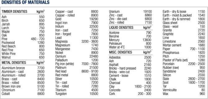
182 Measure 182

183 Measure 183

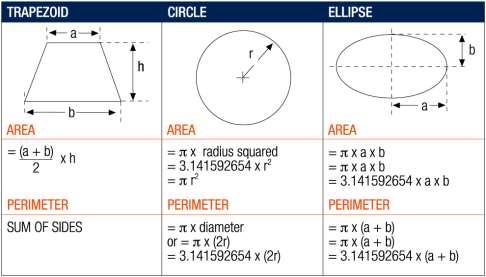
184 Measure 184

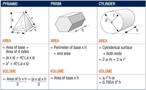
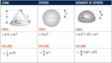
185 Measure 185
186 Measure 186
187 WORKING WITH RMD KWIKFORM Introduction This chapter of the site handbook aims to answer our customer s frequently asked questions about doing business with RMD. Some frequently asked questions are answered below in an attempt to assist the reader to better understand our business and administrative processes. Frequently Asked Questions I am a new customer and would like to open an account with RMD. How long does it take to open an account and what documentation do I need to provide? Firstly you would need to complete an Account Application form (this form can be obtained from your local RMD branch, your Sales rep or please contact us on ) and send it to our Credit Department (christa.viljoen@rmdkwikform.com), together with all accompanying documentation listed below. Company Registration Documents TAX Clearance Certificate Letterhead of your company Confirmation of banking details Proof of business address Copies of all directors Identity Documents We may ask for your latest Financial Statements at our discretion Consult with your sales representative to ensure that the credit limit that you apply for is sufficient for the size of the project you need supplied (as a rule of thumb, a credit limit to the value equivalent to two months of hire at project peak should be sufficient). Admin Please make sure that all fully completed documentation is sent through timeously and that the Account Application is filled in and signed by an authorised signatory, as this will help speed up the process. Once all documentation has been received, a credit check will be completed on the company. Please note, this process can take between hours, and no equipment can be released before an account has been successfully opened. How long are RMD quotes valid for and what terms and conditions are applicable? Quotations are valid for 14 days. Quotes for equipment and/or transport are done subject to availability. All quotes are subject to our standard terms and conditions refer to the Terms and Conditions later in this chapter. 187
188 Admin Our Terms and Conditions are printed on the reverse side of all official RMD Kwikform operational documents. I have reviewed your quote and am ready to place an order. How do I place the order? Furnish us with a purchase order referring to the relevant RMD quotation Purchase orders should be done in writing, on the customer s official letterhead Sign the quote and attach it to your order The signed quote and related purchase order must be ed or faxed to your RMD sales representative. What happens if the equipment RMD quoted on is not available when I place the order? RMD will endeavour to source the equipment from other branches (please bear in mind that this may delay delivery) For the reason above, it is strongly recommended that you finalise your order as soon as possible to prevent any possible delays as our quotations are always subject to availability of equipment If the quoted equipment cannot be sourced locally, we will process a substitution. This means that we will provide an alternative item / product with which to complete your project The customer will be requested to approve the substitution What are the customer s responsibilities on delivery of equipment? As per our standard Terms and Conditions, legal liability for our equipment passes to the customer when it leaves our yard We recommend that our customers count all equipment upon receival, with the RMD representative to ensure that quantities match delivery notes If discrepancies are identified, RMD should be notified in writing. Correspondence can be directed to your RMD sales rep, RMD ops manager and RMD administrative manager of your dispatching branch Picking Lists and Delivery Notes should be signed and notes should be taken of any possible back orders that exist. Customers should note back orders in writing on each Delivery Note. Paperwork may be returned via the RMD truck driver Should external transport be used, the customer should still ensure the above documentation is completed and ed to RMD What are the customer s responsibilities when returning equipment? We recommend that our customers count all the equipment loaded for return with the RMD representative It is recommended that the customer use their own paperwork as an additional control for the amount of equipment returned RMD will count all items upon return and capture the quantities in a Return Note and forward this to the customer for signature by their representatives driver, site personnel etc 188
189 Should discrepancies occur between customer quantities returned and RMD quantities in the yard, RMD should be notified in writing immediately In the case of on-site collections, customers must sign the RMD Collection Note. The equipment is rechecked once it arrives back in the RMD yard. The Return Note is then captured and ed to the customer for signature Should external transport be used, the Return Note will be ed to the customer for signature Are we, as the customer, expected to strap and bundle / palletise the equipment when returning? Yes. This is a health and safety requirement as unstrapped equipment constitutes a safety risk when offloading a truck. Equipment Handling Notes for each class of items are available from RMD Please note, at RMD Kwikform SA, we use forklifts to load and offload vehicles. All vehicles loaded or offloaded must be a flat bed, or a drop side truck, to ensure easy access for the forklift. As per our policies & procedures, RMD yard staff are not permitted to climb onto any vehicle to offload equipment by hand. Admin How are discrepancies dealt with? Should a customer identify a discrepancy on either delivery or return of the equipment, the customer should notify RMD in writing and present their own paperwork to assist in solving the discrepancy. RMD will then: Compare movement of items as per RMD reports to the actual delivery and/or return Identify any capturing or counting errors that may have occurred Conduct a cycle count on the items that have been identified with discrepancies to determine the accuracy of delivery and return counts To facilitate this process, we recommend that you ensure that you have copies of all the delivery and return notes applicable. Please note that only signed documents can be considered in resolving discrepancies. What documents are produced by RMD and how do I interpret each of these? Delivery Note confirms both the items and quantities that have been collected from RMD or delivered to site Return Note confirms both the items and quantities that have been returned to RMD or collected from site Site Status confirms the balance outstanding on specific items on all active sites of a customer 189
190 Admin Project Movement a project specific summary for the quantity of each item delivered and returned during a project, from the first delivery note to the last return note Project Balance shows the balance of all the items delivered, returned as well as all sales invoiced for dirty, damaged, scrap and sell-by-loss items The opening balance refers to the quantity and items on site as per the previous month s closing balance The closing balance refers to items and quantities after the movement for the whole month has been taken into account individual deliveries and returns will be listed on the invoice to confirm the closing balance. The closing balance will ALWAYS match the opening balance of the next month of the same project Each delivery will be added to the quantity and hire whereas the returns will be subtracted from quantity and hire for the day applicable to each transaction Which types of reconciliation requests exist? We typically receive 2 different types of reconciliation requests: Stock Enquiry Request - Serves the purpose to solve delivery and return discrepancies Invoicinig/Pricing Enquiry - To resolve discrepancies between invoicing and pricing and original quotation We aim to make doing business with us as simple as possible and we would welcome your feedback to improve our processes. If you have any suggestions on how/where we can improve or streamline our processes, please get in touch by sending an to: customerservice@rmdkwikform.com Attachments included: Attachment 1 - RMD Quotation Attachment 2 - RMD Delivery Note Attachment 3 - RMD Hire Return Note Attachment 4 - RMD Tax Hire Invoice Attachment 5 - RMD Statement 190
191 Attachment 1 Star Trading 112 Old Main Road Pinetown Nedbank Office Block 12 Payne Street Pinetown Admin 1. Unit Rate = Price of one of the items per week. (excl VAT and before discount) 2. Price = The quantity x the unit rate (excl VAT and before discount) 3. Gross Hire Per Week = Your excl VAT costs of all items added together 4. Less Discount = The discount amount given by the rep 5. Net hire = The discounted value for all quoted items less the discount and excl VAT 6. This is the VAT charged & Total hire per week for all items that have been quoted. 7. This is the text line that is added to the quote. There are no costings or values for this. It is purely used as a tool to state headings and any other descriptions regarding the content on the quotation. Customer to sign here RMD staff to sign here 191
192 Admin Attachment 2 Star Trading 112 Old Main Road Pinetown Nedbank Office Block 12 Payne Street Pinetown 1. This is the Text Line that is added to the quotation. There are no costings or values for this. It is purely used as a tool to state headings and any other descriptions regarding the content on the quotation. Customer to sign acceptance of quantities delivered or collected 192
193 Attachment 3 Page 1 Star Trading 112 Old Main Road Pinetown Nedbank Office Block 12 Payne Street Pinetown Admin 1. Not Repairable means that an item is damaged beyond repair. Once the return is posted, it will automatically create a quote for the scrap charge. The rep will present this quote and photos to the customer. Once the quote is signed and the order received, the charge will be processed. 2. Repairable means that an item is damaged, but can be repaired. Once the return is posted, Axapta will automatically create a quote for the repair charge. The rep will present this quote and photos to the customer. Once the quote is signed and the order received, the charge will be processed. 3. Cleaning means the equipment was returned in a dirty state and was not able to go out again straight away. The same process will follow as per the Repairable charges. 193
194 Admin Attachment 3 Page 2 1. The costs will reflect on the captured Return Note Customer to sign acceptance of quantities delivered or collected 194

195 Attachment 4 Page 1 Star Trading 112 Old Main Road Pinetown Opening balance reflects what was on site at the end of the previous month Nedbank Office Block 12 Payne Street Admin 1. This is the cost per item per week excl VAT 2. This is the quantity on site, delivered or returned 3. This is the rate per week for the quantity of items x the unit rate per week excl VAT 4. This is the number of days you are charged for an item. 5. This is the unit rate per day multiplied by the number of days 6. This shows delivery that has been captured. This includes the Delivery Note number and the on-hire date. Deliveries recorded on invoice for the month 195
196 Admin Attachment 4 Page 2 Star Trading 112 Old Main Road Pinetown Nedbank Office Block 12 Payne Street Pinetown Returns recorded on invoice 1. This shows a return that has been captured. It also shows the return date (the date it is off-hire from), the quantities returned and the amount of days is has been credited for. 196
197 Attachment 4 Page 3 Star Trading 112 Old Main Road Pinetown Nedbank Office Block 12 Payne Street Pinetown Admin 197
198 Admin Attachment 4 Page 4 Star Trading 112 Old Main Road Pinetown Nedbank Office Block 12 Payne Street Pinetown Closing balance reflects kit on site after deliveries and returns have been recorded. The closing balance will match the opening balance on the next month s invoice 1. Charges This amount is what the equipment in your opening balance is charged at for 31 days. 2. Deductions for returns this amount is the cost deducted for all returns done during the course of the month. 3. Charges for new deliveries This amount is the cost charged for all deliveries sent to site. 4. Net Total Charges This amount is the final hire charge for the month. It is worked out by taking the opening balance charge and subtracting the returns charges and adding the delivery charges. 5. This amount is for any transport that has been charged throughout the month, and then added to the net hire amount. 6. This amount is your final invoice amount plus VAT. 198
199 Terms and Conditions THE CUSTOMER S ATTENTION IS PARTICULARLY DRAWN TO CLAUSE 21 DEFINITIONS 1. Customer means the company or individual hiring or purchasing the Equipment from the Owner 2. Customer Requirements means those requirements set out in the technical proposal forming part of the Quotation 3. Equipment means all plant, machinery, equipment and components which the Owner agrees to sell or hire to the Customer 4. Owner means RMD Kwikform South Africa (Pty) Ltd 5. Quotation means the quotation attached to these Conditions. (NOTE) 6. Price means the purchase price in the case of all Equipment for purchase and the rate of hire in the case of all Equipment for hire multiplied by the number of days for which the Equipment is hired, both as stated in the Quotation or as otherwise agreed between the Customer and the Owner from time to time. INTERPRETATIONS 1. Headings will not affect the construction of these Conditions 2. These Conditions apply to both the hire and the sale of Equipment saves where specifically stated otherwise Admin CONDITIONS OF TRADING 3. The Quotation and these Conditions comprise all the terms of contract between the owner and the Customer (the Contract) to the exclusion of all other terms and conditions, including without limitation any of those which the Customer may purport to apply under any hire order, confirmation of hire purchase order confirmation of order or other similar document. No conduct of the Owner shall constitute acceptance of any terms put forward by the Customer, and no addition to or variation of these Conditions shall be binding on the Owner unless agreed to and signed in writing by a director of the Owner. A verbal, faxed or ed instruction by the Customer to deliver Equipment noted in the Quotation will constitute acceptance of the Quotation and these Conditions. 4. Any Quotation given by the Owner is valid for 14 (fourteen) days only from its date provided the Owner has not previously withdrawn it. 5. The Owner hereby hires and/or sells to the Customer the Equipment at the Price upon the terms and subject to these Conditions hereinafter appearing. 6. In respect of any hiring of the Equipment, hiring will commence on the date on which the Equipment leaves the Owner s premises for delivery to the Customer s site or delivery address named in the Quotation or the date the Equipment is made available for collection by the Owner or its agents, and shall continue until the Equipment is returned or should have been returned to the Owner in accordance with these conditions. The Customer must hire the Equipment for a minimum period of 4 (four) weeks. 199
200 Admin DELIVERY AND RISK 7. When the Equipment is ready for delivery the Owner will give the Customer notice of readiness for collection. The Customer shall then give the Owner 10 (ten) day s written notice that either: (a) It intends to collect the Equipment and the Customer shall then collect same on a date notified to the Owner, which date shall be within 10 (ten) days of such notice, or (b) If previously agreed in writing that the Owner shall provide transport, a request that such transport be provided at the Customer s sole expense and the Owner and Customer will then agree a date for delivery PROVIDED THAT time for delivery of Equipment by the Owner shall not be made of essence. 8. If the Customer fails to collect the Equipment within 10 (ten) days of the Customer s notice given under Clause 7 and he has not agreed with the Owner that the Owner will deliver the Equipment in accordance with clause 7(b), then the Owner may: (a) Treat the Customer s failure as a repudiation of the contract with immediate effect in which case the Owner may: (i) Recover from the Customer all losses caused by the Customer s breach; (ii) (iii) Retain any payment made by the Customer before termination of the Contract; Recover from the Customer the cost of hiring the Equipment for the minimum 4 week period referred to in Clause 6 above; and hire or sell the Equipment to somebody else. 9. The Owner will endeavour to have the Equipment ready for delivery by the date agreed for delivery or collection in accordance with Clause 7 but shall not incur any liability whatsoever nor shall the Customer be entitled to terminate the Contract, by reason of the Owner s failure to deliver or have available for collection by the agreed date. 10. In the event that the Owner agrees to deliver the Equipment, he shall deliver such Equipment to the Customer s site or address named in the Quotation. The Owner shall arrange carriage of such Equipment to such site or address and the costs of and associated with such carriage, as specified by the Owner to the Customer, shall be reimbursed to the Owner forthwith by the Customer. 11. The risk in all Equipment delivered by the Owner in accordance with Clause 10 shall pass to the Customer as soon as the Equipment leaves the Owner s premises. The risk in all Equipment collected by Customer from the Owner s premises will pass to the customer immediately on collection. 12. The Owner may deliver the Equipment by instalments of any size and any order. Each separate instalment shall be invoiced and/or paid for in accordance with the Contract. 13. The Owner will prepare an Equipment delivery note for each delivery or collection Equipment describing the Equipment forming part of that delivery of collection. At the time of such delivery or collection, a copy of the delivery note will be given to the Customer and shall constitute proof of delivery or collection of the Equipment. 200
201 14. The quantity of any consignment of Equipment as recorded by the Owner upon despatch from the Owner s place of business shall be conclusive evidence of the quantity received by the Customer on delivery unless the Customer produces conclusive evidence proving the contrary within 24 hours of the Equipment being delivered. 15. The Customer is responsible for the unloading of all Equipment at the Customer s site or address named in the quotation, and shall supply suitably qualified labour and plant to facilitate the same. The Owner s employees and those of any transport company it employs are not responsible for the unloading of any Equipment at the Customer s site or address named in the Quotation and will not assist in same. 16. If the Owner delivers to the Customer a quantity of Equipment of up to 5% more or less than the quantity accepted by the Owner, then the Customer shall not be entitled to object or reject the Equipment by reason of the surplus or shortfall and shall for the Equipment at the pro rata Price. 17. Without prejudice to Clause 16 above, the Owner shall have no liability to the Customer in respect of any shortfall in Equipment delivered or collected unless the Customer gives the Owner notice of the shortfall within 3 (three) days of delivery or collection. If the Customer does give such notice: (a) The Owner may at its sole discretion either Admin (i) Make good the shortfall by one or more deliveries; or (ii) Reduce the Price by the same proportion as the shortage bears to the Contract quantity. 18. The Customer shall not be entitled to reject any delivery on the grounds of any excess or short delivery, but shall pay the Price or where the Owner exercises the option in Clause 17(a) (ii) above, the reduced Price in accordance with that provision. 19. If the Customer rejects the Equipment upon delivery or collection of the same for any reason other than the circumstances described in Clause 18, the Customer shall notify the Owner forthwith. The Owner will then examine the Equipment and if any are found not to conform to the Customer s Requirements, the Owner may: (a) At its own expense replace the Equipment found not to be in accordance with the Customer s Requirements; or (b) Reduce the Prize by any amount equivalent to that proportion of the Price payable in respect of the Equipment found not to conform to the Customer s requirements. 20. The Customer shall in any case accept and pay the Price for all Equipment which conforms to the Customer s Requirements. 201
202 Admin OWNER S LIABILITY 21. The Owner shall exercise reasonable skill and care to ensure that the Equipment and any drawings, designs, measurements or specifications provided by the Owner satisfies the Customer s Requirements subject to the following: (a) The Owner shall have no liability for any alleged failure of the Equipment or any drawings, designs, measurements or specifications supplied by the Owner arising out of or in connection with any inaccurate incomplete conflicting or ambiguous information drawing design or specification supplied by the Customer and used by the Owner as the basis for providing the technical proposal forming part of the Quotation. (b) The Owner shall be under no liability in respect of any defect arising from fair wear and tear, willful damage, negligence, abnormal working conditions, failure to follow the Owner s instructions (whether oral or in writing, misuse or alteration or repair of the Equipment without the Owner s approval. (c) The Owner shall have no liability in relation to parts, materials or equipment not supplied by the Owner. (d) The Owner shall have no liability for any alleged failure of the Equipment or any drawings, designs, measurements or specifications supplied by the Owner to satisfy the Customer s Requirements if such failure is not notified by the Customer to the Owner forthwith following the Equipment being delivered /collected as applicable. (e) The Owner shall not be liable for any damage to property of any kind or any economic loss suffered by the Customer as a result of the failure of the Equipment or any drawings, designs, measurements or specifications supplied by the Owner to conform to the Customer s Requirements including loss of profits, loss of business, loss of production, loss of goodwill or other consequential losses. (f) The Owner shall have no liability if the Equipment is not fit for purpose and all other conditions, warranties, stipulations, and undertakings, whether express or implied by statute or common law. (g) The Owner shall have no liability if the Customer breaches Clause 37 or any part thereof. (h) The Owner s liability to the Customer pursuant to these conditions shall be limited to that proportion of the Customer s losses which it would be just and equitable to require the Owner to pay having regard to the extent of the Owner s liability for the same. 22. Without prejudice to Clause 21 above the Owner s maximum overall liability under or in connection with the Contract shall be limited to a maximum of 10% of the value of the price. PAYMENT 23. In the case of Equipment for hire, the Owner will issue an invoice to the Customer for the Rental and any other amounts due in accordance with these conditions on the last working day of the month in which the Equipment is delivered or collected or in which other amounts become due and on the last working day of every month thereafter until the date the Equipment is returned to the Owner in accordance with these Conditions. Payment is due 30 (thirty) days from the date of the invoice. Time shall be of the essence in respect of the payment of all sums due hereunder. 24. In the case of Equipment for purchase, where the Customer has no agreed credit facility with the Owner at the time of delivery of the Equipment, the Price of such Equipment together with any other amounts due under the Contract shall be invoiced and payable prior to or immediately 202
203 25. upon delivery of the same. Payment may be made by credit card, debit card or Cheque (allow 5 days for Cheque clearance). 26. In the case of Equipment for purchase, where the Customer has an agreed credit facility with the Owner at the time of delivery of the Equipment, the Owner may invoice the Customer for the Price of such Equipment together with any other amounts due to the Owner under the Contract at any time after delivery and the Customer shall pay the Price within 30 (thirty) days of such invoice. 27. The Owner may at any time stating their reasons withdraw with immediate effect the Customer s credit facility. 28. All payments due hereunder (if not made by direct debit or banker s order) shall be made to the Owner without any deduction or set-off for any alleged shortfall in delivery defect in quality or failure to conform to the Customer s Requirements or other breach of contract. Payment shall be made at the Company s address stipulated in the Quotation or such other address as the Owner may from time to time communicate to the Customer. Time shall be of the essence in respect of the payment of all sums due hereunder. Any payments sent by post shall be so sent at the risk of the Customer. Admin 29. The Customer expressly acknowledges and accepts that the Owner shall be entitled to revise the Rental (by such amount as the Owner shall in its absolute discretion determine) in the event that costs of materials, labour or transport increase. Any such revision shall be notified by the Owner to the Customer not less than 2 (two) weeks before the date the revised Rental takes effect. 30. The Customer shall pay interest on all Rental and/o other amounts due in accordance with these Conditions which are paid late at the rate of 4% per annum above the prime overdraft rate charged by the Owner s principle Commercial Bankers in South Africa in force from time to time and all additional administrative costs incurred by the Owner in recovering any late payment, all such amounts being calculated from the due date for payment of such Price until actual payment of the same. 31. The Price and any other amounts due in accordance with these Conditions is exclusive of VAT, if any, which shall be due at the rate prevailing on the date of the VAT invoice, and any other tax or levy which the Owner is or shall be liable to pay or collect. 32. In the event of any breach by the Customer of any term warranty or condition of these conditions, the Customer shall if required by the Owner pay any invoice rendered to the Customer immediately. 33. Equipment supplied under any other contract with the Owner) as the Owner may in its sole discretion think fit. 203
204 Admin PROPERTY 34. In respect of Equipment for hire the Equipment shall at all times remain the property of the Owner and the Customer shall have no rights to the Equipment other than as hirer and the Customer shall not do or permit or cause to be done any matter or thing whereby the rights of the Owner in respect of the Equipment are or may be prejudicially affected. 35. In respect of the Equipment for sale, property in such Equipment shall not pass to the Customer until payment of the Price in full in accordance with these Conditions has been received by the Owner. 36. Until property in the Equipment for sale passes to the Customer in accordance with these Conditions, the Customer shall hold them as bailey for the Owner and shall store them separately from any similar equipment of the Owner or any other person in such a way that they remain identifiable as the Owner s property. 37. The specification(s) drawing(s) and design(s) relating to the Equipment (including copyright, design right or other intellectual property in them) shall as between the Parties be the property of the Owner. Where any designs, drawings or specifications has been supplied by the Customer then the Customer warrants that the use of those designs, drawings or specifications shall not infringe the right of any third party. 38. The Customer must not use the Equipment for any purpose for which they are not expressly designed. The Customer hereby agrees that it will not: 39. (i) Without the prior written consent of the Owner effect any modification or make any alterations or additions to the Equipment; or (j) Remove or interfere with any identification marks or plates affixed to the Equipment and not attempt or purport to do so or permit the same. INSURANCE 40. In the case of Equipment for hire the Customer will throughout the period of the Contract, without prejudice to the liability of the Customer to the Owner, keep the Equipment insured with an insurance company of good repute against loss or damage from all risks (including third party risks) for the full replacement value of that Equipment. The Customer shall notify its insurers that the Equipment is on hire from the Owner and request the insurers to endorse a note of such interest on the policy of insurance naming the Owner as loss payee. The Customer shall on demand show the Owner evidence of the policy of insurance and shall not use or allow the Equipment to be used for any purpose not permitted by the terms and conditions of this policy. If the Customer makes a default in the payment of any premium in respect of the insurance or fails to take out the insurance required by this Clause, the Owner may pay such premium or premiums and recoup the cost of doing so from the Customer. The Customer shall immediately notify the Owner in the event that an event occurs which a risk is covered by the Customer s insurance which the Customer is obliged to take out under the Contract. The Customer shall indemnify the Owner against all loss or damage to the Equipment not recovered under the policy of insurance. 204
205 TERMINATION 41. In the event of the Customer; (i) The Customer (being an individual) dies or suffers an interim order (within the meaning of the Insolvency Act No. 34 of 1936) to be made against him or enters a voluntary arrangement or suffers the making of a statutory demand or the presentation of a petition for a bankruptcy order or make any arrangement or composition with his creditors; or (ii) Failing to comply with any provision of this Agreement and persisting in such failure for a period of 14 (fourteen) days after receipt of a written notice demanding compliance; or (iii) Not paying any amount which is due and payable in terms hereof and persisting in such non-payment for a period of 7 (seven) days after such payment has become due; or (iv) The Customer (being a limited company) enters into compulsory liquidation or voluntary liquidation, being wound up, whether voluntary or compulsory (provisionally or finally) or in the event that business rescue proceedings under Chapter 6 of the Companies Act (Act no. 71 of 2008) have been commenced in respect of it; or Admin (v) Being sequestrated, whether provisionally or finally or whether as a consequence of the surrendering of this estate in circumstances where the Customer is a natural person; or (vi) Allowing the attachment of any of its assets; or (vii) Suffering a judgment against it which judgment is not satisfied in full or appealed against or in respect of which an application to set it aside or rescind it is not made within ten (10) days after it becomes known to such party; or (viii) Entering into a compromise with its creditors or with any class of creditors or make any assignment for the benefit of creditors or do anything which would amount to an act or insolvency as defined by the Insolvency Act (Act no. 24 of 1936); or (ix) Having any license to conduct its business suspended, removed or endorsed by any order or decree of any applicable authority, or being convicted of fraud or if any director or senior manager of the Customer is convicted of fraud in relation to the business covered by this agreement; or (x) Doing or causing to do anything whereby the Owner s right sin the Equipment are prejudiced or put in jeopardy in any way; (xi) Any distress, execution or other legal process shall be levied on or against the Equipment or any part thereof or against any Premises where the same may be: then any hire constituted by the Contract shall terminate without notice and no payment subsequently accepted by the Owner without knowledge of such termination shall in any way prejudice or affects the operation of this Clause. 205
206 Admin Then the Owner shall be entitled, without prejudice to any other right it may have in terms of this agreement or in law, to: 1. Cancel this agreement and claim damages from the Customer; and 2. Claim specific performance of any or all of the terms and conditions of this agreement. 42. If and on each and every occasion on which: (i) The Customer shall fail to pay any Rental or other sums payable under the Contract in full within 7 (seven) days after the same shall have become due; or (ii) The Customer shall commit a breach of any of the other terms of the Contract (if capable of being remedied) shall fail to remedy the breach within 14 (fourteen) days after notice in writing from the Owner requiring the same; or (iii) The Customer shall do or cause to be done anything whereby the Owner s rights in the Equipment are prejudiced or put in jeopardy; or (iv) If the Owner so decides for any other reasonable cause; then the Owner shall have the right to terminate the Contract forthwith and for all purposes and be entitled to demand return of any or all Equipment in the possession of the Customer within a period of 5 (five) days of the date of notice demanding return, and the Customer hereby undertakes to return any or all Equipment to the Owner within such period at tis costs. 43. At the end of the hire of any Equipment or on earlier repudiation or termination in accordance with the Contract: 44. (i) All Equipment must be returned to the Owner forthwith at its premises where the Equipment was originally supplied (unless otherwise specified by the Owner) in good repair and in a clean and sound condition (fair wear and tear only accepted) and the Customer shall ensure the safe-keeping, supervision and custody of the Equipment until it is returned or repossessed by the Owner. The Customer shall be responsible for the loading of all Equipment being returned in accordance with all relevant health and safety legislation and guidance. In the event the Owner does not in its opinion believe that the Equipment has been safely loaded the Owner has the right to send the same back to the Customer for safe loading in which case the period of hire will continue until the Equipment has been returned to the Owner in what the Owner in its sole discretion considers is a safe condition. The assessment of the condition of Equipment shall be made solely by the Owner acting reasonably whose assessment shall be binding on the Customer. (ii) (iii) The Customer shall fully reimburse the Owner for all charges and costs incurred by it for cleaning or repairing damaged or defective Equipment as notified to the Customer. The Customer shall pay the full replacement cost of Equipment listed in the Quotation for all lost or irreparable items as specified by the Owner, based on the Owner s price list current at the date of the repudiation or termination as appropriate. (iv) In the event that the Customer fails to return the Equipment within 14 (fourteen) days of being obliged to, the Owner may forthwith and without notice retake possession of such Equipment and for this purpose shall be entitled freely to enter into and upon any premises occupied by or under the control of the Customer. In the event that the Equipment is 206
207 (v) (vi) situated on premises which are occupied or controlled by a third party, the Customer shall ensure that it has made sufficient arrangements with the third party to enable the Owner to enter onto such premises in order to exercise its right under this Clause to retake possession of the Equipment. Without prejudice to the Owner s rights to claim damages the Customer shall on termination or repudiation of that Agreement become immediately liable to pay to the Owner all arrears of Rental, any other amounts due in accordance with these Conditions and any other amounts due and payable and any costs and expenses incurred by the owner in locating, repossessing, and recovering or restoring the Equipment or collecting payments due under the Contract. 45. The Customer shall not be entitled to claim loss of profit or breach of contract in respect of any termination of these Conditions. SUBCONTRACTING AND ASSIGNMENT 46. The Owner, but not the Customer, may assign sub-contract or sub-let these conditions or the Equipment or any part thereof and the Customer shall ensure that all Equipment hired from the Owner remains on the agreed site until returned to the Owner unless otherwise expressly agreed by the owner. Admin MISCELLANEOUS 47. The Owner has designed, manufactured or procured the manufacture of and supplied the Equipment for and to the Customer on the basis of the written undertaking herein that the Customer will ensure that the Equipment will be safe and without health risks when being set, used, cleaned or maintained by the Customer, its employees and/or third party and on the basis that the Owner is relieved from its duty under any relevant legislation, as is reasonable. 48. The Owner will not be liable to the Customer in any civil proceedings brought by the Customer against the Owner under any health and safety legislation and regulations where such exclusion of liability is permitted by law. 49. The Customer shall indemnify and keep indemnified the Owner in respect of any liability, in respect of or in connection with the Equipment incurred directly by the Owner under and relevant legislation. 50. The rights and remedies of the Owner shall not be diminished, waived or extinguished by the granting of any indulgence or forbearance or extension of time by the Owner or by any failure or delay by the Owner in asserting or exercising any such rights or remedies. 51. The Customer agrees that the Owner may cede or transfer its rights under this contract and its ownership in the goods and insofar as such consent may be necessary, the Customer agrees upon such cession of transfer to hold the goods on the basis that ownership therein has passed to the cessionary or transferee subject otherwise to the terms of this contract and to the extent to which this clause may be construed as a stipulation alter in favour of such cessionary or transferee, the Customer agrees that the acceptance of cession of this contract by the cessionary or the 207
208 Admin 52. transferee shall constitute an acceptance by the cessionary or transferee of the benefits arising out of this contract. 53. The Customer consents in terms of Section 45(1) of the Magistrates Court Act No. 32 of 1944 as amended in respect of any proceedings which may be instituted against it by the Owner arising out of or in connection with this Contract, to the jurisdiction of any Magistrates Court which at the time of such proceedings has jurisdiction over it in terms of Section 28(1) of the said Magistrates Court Act. Notwithstanding the a foregoing the Customer specifically agrees that the Owner may in its sole discretion disregard the a foregoing consent to jurisdiction and institute any proceedings arising out or in connection with this Contract in the Supreme Court of South Africa having jurisdiction. 54. A certificate under the hand of any director, any manager or secretary of the Owner stating that any particular sum or sums is/are due and payable by the Customer to the Owner in terms of this Contract or stating the amount of any costs, charges or expenses taken into account in determining the amount of any claim in favor of the Owner against the Customer in terms of this Contract shall be admissible in any court of law and constitute prima facie proof of the contents thereof and shall constitute a liquid document for the purposes of summary judgment or provisional sentence. 55. The purchaser hereby chooses the address shown as its place of business on the front of this document as its domicilium citandi et executandi for all purposes ( the domicilium ). Any notice to be given shall be deemed to be sufficiently delivered to the purchaser 3 days after dispatch by pre-paid registered post to the domicilium, or on date of delivery, if delivered by hand, per or sent by telefax. 56. If any provision in the Contract shall be held to be void, illegal, invalid or unenforceable in whole or in part under any enactment or rule of law such provision or part shall to that extent be deemed not to form part of the Contract but the legality, validity and enforceability of the remainder of such agreement shall not be affected. 57. Nothing in the Contract shall confer or purport to confer on any third party any benefit or right to enforce any term of the Contract in any way whatsoever. 58. The Contract shall be governed and construed in all respects in accordance with the laws of the Republic of South Africa and the Owner and Customer irrevocably submit to the exclusive jurisdiction of the South African Courts. 208

209 Branch Contact Details Head Office 52 Jakaranda St, Hennopspark Centurion 0046 T: Gauteng Branch 52 Jakaranda St, Hennopspark Centurion 0046 T: KZN Branch Unit 1 Greystone Off Ramp, 135 Old North Road, Glen Anil, Durban T: Free State Branch 51 Sand du Plessis Avenue, Estoire, Bloemfontein T: Cape Town Branch 28 Chardonnay Rd, Saxenburg Park, Kuils River, Cape Town T: Admin Mpumalanga Branch 16 Wilken St, Rocky Drift, Nelspruit T: