Replacement of BNSF Bridges near Princeton, IL & near Wyanet, IL. Authors. Number of Words 6875
|
|
|
- Gerald Hopkins
- 5 years ago
- Views:
Transcription
1 Replacement of BNSF Bridges near Princeton, IL & near Wyanet, IL Authors Principal Author Jason E. Cunningham, PE, SE Bridge Engineer Hanson Professional Services Inc N. University St., Suite 200 Peoria, IL Trevor Attwood Manager Structures Design BNSF Railway Company 4515 Kansas Avenue Kansas City, Kansas Number of Words 6875 ABSTRACT Large numbers of old bridges throughout the United States and high traffic volumes require innovative methods for replacement under traffic. Challenges presented by the subject bridges were overcome with unique solutions from design and construction. These 1899 era double track bridges included 120 ft deck truss waterway spans supported at each end by steel towers due to bridge heights approaching 85 ft from track to stream bed. Bridge measured 383 ft face-to-face of backwalls and bridge measured 322 ft. The new bridge design located the main span piers at the center of each tower to provide a reasonable span length (155ft), avoid existing footings and minimize risk of settlement during construction of the drilled shafts. Modification of tower bracing allowed installation of the large cross caps and associated falsework through the tower. The contractor incorporated a number of unique approaches to improve constructability and help reduce outage time. A small lengthening of the cross cap allowed the girders to be erected on the new piers without the use of falsework. Demolition time was aided by rigging the timber ballast decks panels ahead of the outage to allow for liftoff without removal of ballast. The new concrete deck spans supported a gantry system used to lower the existing deck truss to the floodway below. Both bridges were replaced in one 48 hour window and involved more than 275 personnel. The 10mph speed restriction for 286k loads was eliminated resulting in an increase to passenger and freight traffic. INTRODUCTION The two structures associated with this project are owned and operated by the BNSF Railway Company. The bridges are on Line Segment 0001 of the Mendota Subdivision, located just south of Interstate 80 in the northern portion of Illinois. Bridge is a 383-ft double-track bridge over Big Bureau Creek and located approximately two miles west of Princeton, IL. Bridge is a 322-ft double-track bridge over West Bureau Creek and located about one-half mile east of Wyanet, IL. AREMA

2 Line Segment 0001 of the Mendota Subdivision runs from Montgomery, IL,. (western edge of the Chicago suburbs) to Galesburg, IL. The line is commonly called The Mainline by the locals because it was part of the original CB&Q rail line from Chicago to Burlington, IA. The average volume of trains on this line was 24 per 24-hour period, including eight Amtrak trains. Because of the condition of the existing bridges, the speed had been restricted to 50 mph for heavier freight trains. Both bridges were built in 1899, each with an approximate 120-ft main span double-track deck truss, 30-ft tower spans on each side of the main span and multiple deck plate girder approach spans. The support piers for the deck truss were composed of large masonry blocks supported on timber piles. Throughout the history of each bridge, upgrades were made to prolong the life expectancy of each structure. The truss spans were reinforced in 1918 and 1930, and the deck plate girders went through modifications in 1925 and In 1963, the structure went through foundation modifications. At Bridge , a new approach span pier was built on precast concrete piles, and girders of the existing spans were shortened. In addition, new concrete abutments supported on precast concrete piles were built in front of the existing abutments and the existing spans were shortened and re-used. At Bridge , new helper bent piers on precast concrete piles were built and the existing girders modified to be continuous over these new piers. In early 2013, BNSF authorized Hanson to proceed with design and plan preparation for replacement of both double-track bridges on the existing alignment. The initial concept developed by Hanson during the Request for Proposal stage included stretching the main span beyond the existing steel towers. This resulted in deck plate girder spans of 216 ft supported by new drilled shaft and transfer beams. The approach spans were composed of single- or double-voided box beams on the existing foundations. After initial design and discussion, the layout was revised to place new drilled shaft and transfer beam piers at the approximate center of the existing tower spans. This reduced the main spans to a more manageable length of 156 ft for Bridge and 153 ft for Bridge To accommodate the use of 42 standard double-voided box beam spans for the approaches, a drilled shaft and transfer beam pier was built on each side of the main piers. At both sites, the existing abutments were utilized, and at Bridge , the first approach span pier on each end was re-used. Figure 1 General Bridge Elevation 682 AREMA 2016
3 Figure 2 General Bridge Elevation DESIGN CONCEPTS The main parameters for this project were to build on the existing alignment, keep the construction period to one year, limit the disruption to everyday train traffic and provide a structure that could be changed-out in a 36-hour contractor window (48 hours total including BNSF track removal and replacement). The following items were utilized in the design phase in conformance with these goals. One Outage for Both Bridges The distance of approximately 4 miles between structures and the long history of work being done simultaneously at these locations made for an easy decision. During its internal planning phase, BNSF made the decision to replace the two bridges during one outage. The existing bridges were similar, with just a relatively small difference in overall length, which allowed for new structures that would utilize the same elements and techniques for construction. A slight risk to this plan was having enough skilled labor to meet the aggressive task of replacing two double-track bridges at once. The risk ended up being of minimal concern once the contractor began work. The location of the project was near a split between regions among several of the trades, and the contractor was able to negotiate some flexibility to bring workers they were familiar with from the unions in the Chicago area to help bolster the workforce. Re-use of Existing Foundation Elements Regardless of placement behind or in front of the existing abutments, the construction of new abutments would have provided constructability issues leading up to and during an outage. A new abutment behind the existing would have led to challenges in the actual construction of that abutment under traffic with jump spans. Other alternatives would have required driving piling in track closure windows. Then, during an outage, the contractor would need to excavate and weld precast caps to the piles and backfill around the new abutment. At Bridge , the remnants of large abutments already existed behind the current abutments. With construction of new abutments in front of the existing foundations, similar challenges would have existed in trying to build under the existing deep girder end spans and limited the AREMA

4 effectiveness of a cast-in-place concrete abutment. Locations in the deck would have needed to be opened up for driving piles, a larger area would have needed to be backfilled during the outage and tall backwalls would have required attachment during the closure window. At Bridge , the current abutments and the first pier on each end were constructed in The abutments at Bridge were rehabilitated during the same time period. The foundation elements were in good condition and could be re-used as part of the new structure. Precast bearing blocks were used to accommodate the difference in height between new and proposed superstructures. Photo 1 Existing Pier to be Re-used Precast Double-Voided Box Girder Spans The type of superstructure to be placed is a critical component to the cost of a project and plays an important role in the length of a project. Throughout its track system, BNSF uses a set of standard precast double-voided box girders to facilitate quick changeouts of its aging infrastructure. In the case of superstructure, once the bridge seats are in place, the girders can be set quickly in the correct location, ready for track crews to begin ballast placement. For the reconstruction of the bridges at these sites, the use of precast girders for the approach spans was an effective solution for the superstructure. With the decision to re-use some of the existing foundations and arrangement of the other new piers in locations to miss existing foundations, the use of precast box girder spans was easily implemented. The final location of piers was adjusted to provide similar length spans for repetition and necessitated the use of 42 double-voided box girders. Locate Drilled Shafts Outside Existing Deck Another important decision in the design for the two bridges involved the foundations to be used for the piers. The foundations would need to be rather large to support the loads involved with the superstructure, especially for the main span. The use of driven piles was not really an option because of the amount that would be required and the limited space around the existing steel tower foundations. The 684 AREMA 2016

5 clearance above natural groundline was insufficient to construct drilled shafts beneath the existing structure. Also, the large new shafts for the main piers would have been a tight fit among the existing tower footings. The site geometric restraints led to an easy solution of locating the drilled shafts at a suitable construction clearance outside the footprint of the existing superstructure. In the case of the drilled shafts near the existing towers, the location was offset enough that the large 8-ft drilled shafts could be drilled without interference with the existing footings. This effort worked for the actual drilled shaft; however, the contractor did clip one small corner of an existing footing when installing an oversized temporary casing to aid in drilled shaft placement. Photo 2 Drilled Shaft outside Existing Deck Steel Plate Girder Main Spans with Concrete Deck on Falsework To accommodate the main span length of approximately 150 ft, the reasonable superstructure choice was welded steel plate girders. The girders for these spans, while massive in size, are fairly simple members to be fabricated, transported and erected. Research was done during design to provide plate sizes for the web and flanges that would maximize the number of material suppliers available. To facilitate transport, the girders were fabricated with two splice locations that would require final assembly on-site. The assembly would require a significant footprint in the overall work area of the two bridge sites, but with proper planning of delivery schedule as well as erection sequence, the area was limited. The delivery schedule involved three sections of one complete girder per day, which could be properly unloaded to temporary timber mats and cribbing to provide correct camber for the end sections to be spliced to the center section. In addition, the girders were delivered in reverse order of how they were to be erected. As each girder was lifted up and away from the group, the girders were placed tightly together (similar spacing to final positioning) to limit the space in the work area. The concept during design was for the erection of steel falsework near each new pier location with the anticipation of roll/slide new spans into final position during the outage. After assembly, the girders could be erected on the falsework, diaphragms attached between girders and complete bolt-up of the span AREMA

6 finished. The deck would then be formed, concrete deck cast and waterproofing applied prior to the scheduled outage, which would involve the slide/roll-in of the spans. Separate Contract for Access Road Construction at Bridge During the design phase, it was determined that the soil borings taken behind the existing abutments in a prior study of the bridge would be insufficient to determine needed geotechnical data for the drilled shafts. It was decided that a new set of borings would be performed at the location of each proposed drilled shaft. The structure at rises roughly 85 ft above the creek bottom below and has steep slopes all around hindering access to the area for staging the work from below the bridge. To get these new borings, access to the locations was required and would need to be done prior to construction. To save time during the bridge construction, the design team made the decision to let a contract for construction of an access road for the borings that would be suitable for the heavy construction traffic to be used later. Unfortunately, the construction of the temporary access road was unable to start until the end of November, which coincided with the start of one of the worst winters in the area. The start of colder temperatures after construction started was less than ideal for earthwork. During the harsh winter, approximately 4 ft of frost worked itself into the ground. The large amounts of snow cover for most of the winter and a particularly wet, rainy spring added to the conditions of the access road. During the first month of construction, the bridge contractor rebuilt the aggregate section of the access road. Photo 3 Princeton Access Road CONSTRUCTION CONCEPTS In January 2014, the project transitioned to the construction phase, and James McHugh Construction Co. was awarded the project as the general contractor. The contractor s bid documents contained key construction solutions to the design concepts and met the project s time requirements. Additional techniques continued to evolve over the course of the project to enhance these schemes. The following items outline solutions to some of the construction issues. 686 AREMA 2016

7 Transfer Beam Falsework At the start of the project, McHugh Construction had a contract with the Illinois Department of Transportation in the Chicago area to replace several bridges of an interchange. The structures being replaced provided large amounts of W36 beams, perfect for using as falsework to support the large transfer beams that would be a part of the new bridge structure. The falsework would be needed to support nearly 1million pounds of concrete, reinforcement, forms, decking and associated construction loading. The falsework system was supported by a series of seat brackets welded to embedded plates in the concrete columns. To construct the new concrete transfer beams, bracing was modified on the existing steel towers. During this process, the speed for all trains was reduced to 25 mph while each brace was removed and reconfigured. Photo 4 Transfer Beam Falsework Extend Length of Transfer Beams With the placement of the drilled shafts outside the existing structure and the transfer beams having a slight overhang to the outside of the columns, the result was a large open space to the outside of the existing superstructure. This available area set the wheels in motion for the next solution to the construction challenges. In an effort to avoid building tall steel falsework to support the main spans, the contractor proposed a small extension to the transfer beams, providing a temporary location for the steel girders prior to a roll/slide-in during an outage. The dimensions of the proposed transfer beam and location of a temporary placement of the steel superstructure on each side in relationship to the existing superstructure were reviewed. The result was an extension of the transfer beam length by 10 inches on each side. The change was made early in the process, so reinforcement and post-tensioning rods and ducts could be ordered to correct length and the quantity of shear reinforcement bars could be increased. After completion, the girders were placed comfortably to have some clearance to the outer edge of the transfer beam and still provide enough clearance to the existing structure to place overhang forms for the concrete deck. AREMA

8 Photo 5 Temporary Steel Placement Removal of the Existing Timber Deck A key element in the removal of the existing structure centered on the removal of the timber deck. As is customary in old railroad bridges, the level of ballast had been built-up over time. The increased weight of ballast on the structure complicated the logistics of removing the ballast, deck and girders. There is an increase in time if done separately, but it is difficult to accomplish when done as one pick without massive cranes or a small lifting radius. During planning for the outage, a concept was developed that allowed the ballast and deck to be stripped off quickly and the girders lifted from their existing locations. Before the outage, the contractor rigged many of the items to allow for easy access and removal during the outage. The ties were outfitted with eye bolts and a cable strand strung between four or five members and attached to the outside curb to allow for removal at the same time as the deck. The inside curbs on each deck were strung with cable, wedges placed between the adjacent curbs and thru-bolts removed. Then during the outage, the cables were quickly unearthed, hooked on a crane and pulled. On the outside of each deck panel, rigging was strung through the existing drain holes and half the connection bolts were removed from the girders below. During the outage, while rail and curb removal was taking place, the remaining connection bolts were removed. The rigging was attached to a crane and lifted. By connecting from the outside, the panel lifted from the exterior edge and began spilling the ballast between the tracks to the ground below. Sheets of plywood were used to protect the bearing seats of the piers and abutments from the falling debris. The process was systematically implemented, exposing the girder spans in a set order required to begin an additional task in the change-out. 688 AREMA 2016

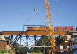
9 Photo 6 Existing Deck Removal Removal of the Existing Girders With the large amount of extra weight of ballast and timber deck removed from the girders, the cranes could be placed in one location and safely accommodate the radii of the required lifts. Prior to the outage, crews accomplished rigging with the use of reinforced holes placed in the web and chains to easily attach to the crane. In the weeks leading up to the outage, bolts were used as replacements for rivets in the connections to the towers, bearings or pedestals. The nuts on the bolts were easily removed the morning of the outage. With the reduced weight, the girders could be removed in pairs, which reduced the time to disconnect or cut through the cross bracing. To reduce the time needed during the outage, the existing girders had to be removed in a certain order. To begin drilling the required holes for placement of dowel bars for the precast bearing blocks, the end spans were removed first to expose the existing abutment seats at both sites. To place the gantry crane system to lower the truss, the small spans over the end of the deck trusses needed to be removed. Prior to removal of the steel towers, the adjacent spans needed to be removed before cutting on the legs could begin. At Bridge , the second span on each end needed to remain in place so a small excavator with a jackhammer attachment could remove an existing concrete block from the pier. Once that task was complete, the span was removed to commence with drilling dowel bar holes. Removal of the Existing Double-Track Deck Truss The removal of the existing double-track deck truss presented a large challenge to McHugh Construction when planning for the outage. The overall size of the truss and general site constraints made it difficult to lift out and set down. The advantages gained in the temporary placement of the new superstructure main spans would be negated by a system put in place to roll the deck truss out of position. The solution ultimately selected involved a gantry crane assembly to efficiently lower the deck truss down and allow for the new steel spans to be slid into place easily. AREMA

10 The system used the proposed composite bridge girder spans that were temporarily placed on each side of the existing deck truss as support for the hoist and gantry system. Large timber mats were placed on the deck to spread the load out and protect the previously applied waterproofing system. Two large steel frames were constructed to support the eight hoist locations that would be utilized to lower the deck truss. After removal of the existing timber deck and steel girder span above, each support frame was lifted into position on the proposed decks and the 50-ton air chain hoists were attached with chains at the predetermined locations. Once the diagonals and bottom chords were fully cut through at each end, the deck truss was lowered in about 20 minutes. The truss was placed on a series of timber cribbing until being dismantled after the outage. Photo 7 Gantry Crane Assembly Slide System for New Steel Spans To move the new steel spans from the temporary location on the transfer beams to their final location, the contractor used a slide system from Barnhart Crane & Rigging Co. The first design modifications for the use of this system occurred early in the construction process. The distance between pier cap and bottom of the girder flange provided minimal height to place the large jacks to lift and lower the superstructure. During the construction of the transfer beams, large steel embed plates were needed to allow for the welding of cantilevered brackets that would support the slide system. In addition, a new jacking diaphragm had to be added at an established distance off the end of the girders. A large portion of the system was able to be placed into position in the weeks leading up to the outage. During the outage, the procedure first required a simple lifting of the structure with the large cylinder jacks situated on top of the transfer beams. After the structure was lifted sufficiently, the slide shoes were placed on the slide beam and the girders lowered down onto the shoes. Hydraulic jacks were then used to slowly move the girders into their final position and the cylinder jacks were moved. At the final location, cylinder jacks were used to lift the structure up to remove the slide shoes and the girders lowered down to the transfer beams. At each bridge, the two spans were slid in toward each other simultaneously and required approximately two to three hours at each site. 690 AREMA 2016
11 Bearing Blocks at Abutments One of the most time-consuming work items of the outage was the drilling of the holes for the dowel bars for attachment to the existing abutments and piers. Most of these blocks were fairly tall and subject to large overturning moments from longitudinal and lateral loads and required a high number of dowels. A few months before the outage, it was discovered that the existing abutment bearings were also sitting on steel grillage embedded in the concrete and would interfere with a portion of the dowel holes. Hanson and BNSF reviewed the information and possible solutions to address the problem. The precast bearing blocks for each track at the abutments would be fabricated with three lateral holes to allow for horizontal tiebacks. Under a separate contract after the outage, a specialty contractor would mobilize and drill into the backwalls and soil behind the abutments to provide tiebacks, connected with a channel on the front face. For the outage, the number of holes to be drilled were reduced to avoid the grillage and additional embedded plates were welded to anchor plates attached to the existing abutment to provide additional lateral resistance. Miscellaneous Items Multiple small and sometimes overlooked processes were instrumental in the implementation of the outage. BNSF provided a series of portable stairs that were placed by the contractor to ascend the tall treacherous slopes and provide safe access to the existing abutments. A series of plywood templates were developed ahead of time from the as-built dimensions of the bearing blocks to assist in the marking and subsequent drilling of dowel bar holes. To better inform employees who were new to the sites during the outage, substructures were clearly labeled with large plywood signs and existing timber deck sections marked as reference points. Cut locations on the steel towers, girders and trusses were clearly marked, as well as bolts in need of removal. The bridge sites were mapped out to document the placement of new material waiting to be used and the sections of the existing structure to be scrapped. CONCLUSION In the age where many late 19 th century and early 20 th century railroad bridges begin to exceed even the most ambitious of life expectancies that were hoped for back in the time of construction, design engineers and contractors are faced with the challenges of replacing these structures with minimal impact to existing rail traffic. During this project, the best of both worlds meshed to provide an outstanding end product. The design team of Hanson and BNSF started with general concepts to accomplish the work and the contractor, James McHugh Construction Co., provided the ingenuity to take these concepts and enhance them to feasible processes during construction. BNSF handed over the two bridges to the contractor to begin the removal and replacement at approximately 7a.m. on Nov. 15, Throughout the day, the implemented items allowed the changeout to proceed ahead of schedule. However, as might be expected when the best of weather is hoped for when the date is set two months in advance of the outage, the weather deteriorated as the work continued into the evening. Light snow, increased wind and dropping temperatures were never extreme enough to stop work, but they made the process a challenge. The bridge at was turned back to BNSF track crews a couple hours early at around 5 p.m. on Nov. 16. The bridge at was completed and returned to BNSF around 2a.m. on Nov. 17. BNSF track crews worked to get Main Track #1 open to rail traffic within the 48-hour window around 8 a.m. on the morning of the 17 th. Most importantly, there were no injuries or accidents during this major bridge change-out. AREMA

12 Photo 8 First Freight (at Wyanet BR ) LIST OF FIGURES Figure 1 General Bridge Elevation Figure 2 General Bridge Elevation LIST OF PHOTOS Photo 1 Existing Pier to be Re-used Photo 2 Drilled Shaft outside Existing Deck Photo 3 Princeton Access Road Photo 4 Transfer Beam Falsework Photo 5 Temporary Steel Placement Photo 6 Existing Deck Removal Photo 7 Gantry Crane Assembly Photo 8 First Freight (at Wyanet BR ) 692 AREMA 2016


13 Jason Cunningham & Trevor Attwood AREMA


14 Project Location Project Team Client: BNSF Railway Co. Contractor: James McHugh Construction Co. Drilled Shafts: Michels Foundations Inc. Steel Fabricator: DeLong s Inc. Construction Engineering: GEI Consultants Inc. Design & CM : Hanson Professional Services Inc. Princeton Princeton Wyanet Temporary Stream Crossing SITE ACCESS Access Road East Embankment Wyanet Morning Rush Hour??? Laydown SE Quad Sheet Pile West Side 694 AREMA 2016


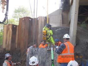

15 Tight Quarters DRILLED SHAFTS Telescoping Casing Main Piers 8-0 Dia. Drilled Shaft Cage Approach Piers 5-6 Dia. Lost Clean Out Bucket Wyanet Br GREAT FLOOD AREMA


 x 10")

 x 8-")


16 Princeton Wyanet Br Wyanet Back in Action TRANSFER BEAMS Main Piers 8-6 (w) x 10 0 (h) Approach Piers 6-0 (w) x 8-0 (h) 696 AREMA 2016


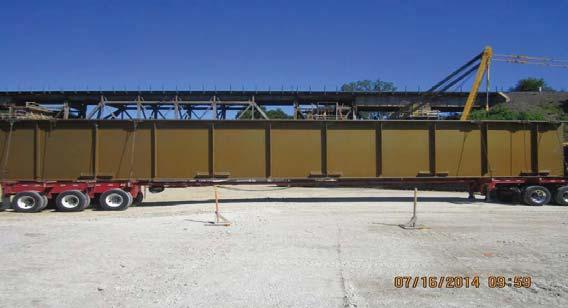


17 STRUCTURAL STEEL Each Girder 2 x25 Flanges 7/8 x114 Web Princeton Length Wyanet Length AREMA


18 OUTAGE PREP Wyanet and Princeton 48-hr Track Outage BNSF Railway Mendota Sub November 15-17, 2014 Window Schedule Key Facts 48-hr Window 275 Personnel 7 Workgroups 705 of new bridge, double track BR & Rebuilds BNSF Construction Challenges 5 cranes including 900TN at Wyanet 3 unique removal methods Low temps, snow and wind Track crews on an island Track work/crews tiein 8 transitions on 4 bridges 698 AREMA 2016


19 Track Removal 11/15, 0500 Unique Deck Removal 0630 Double-rail sliders Pre-rigging of tubs BR Pre-rigged DPGs BR Pre-rigged DPGs DPG Removal 0800 BR Princeton, IL Existing girders hoisted by 900 TN and 500 TN cranes AREMA


20 BR Wyanet, IL Truss Demolition / Lowering Trusses are cut by torch 119 long, 118 TN Lowered by 400 TN capacity pneumatic gantry DPG Roll-in Tons per track Pre-Cast Approaches Install 28 bearing blocks 40 double cell box beams range DPGs are hydraulically rolled into position toward center of bridge Time-lapse BR Track Install 22 track panels 14 ballast cars 2 Brandts, 3 surface crews 700 AREMA 2016


21 Return to Service 0645 FINAL PRODUCT Princeton Wyanet VACATION AFTER THE JOB IS DONE! Jason goes here Crane goes to Bahamas THANK YOU! AREMA