INTERNATIONAL JOURNAL OF APPLIED ENGINEERING RESEARCH, DINDIGUL Volume 1, No 2, 2010
|
|
|
- Lucinda Taylor
- 5 years ago
- Views:
Transcription
1 Micro Mechanical Measurement of Concrete Strain to Evaluate Principle Strain Distribution in Steel Fiber Reinforced Cement Concrete Moderate Deep Beams across it s width and depths Vinu R. Patel, I. I. Pandya Department of Applied Mechanics, M.S.University, Baroda. zarnaasso@yahoo.com ABSTRACT This paper investigates the distribution of principal strain by micro mechanical measurement of concrete axial strain in Steel Fiber Reinforced Cement Concrete moderate deep beams across its width and depths for various span to depth ratios. A complete shear deformational behavior along with load deflection response, crack patterns and modes of failure was studied experimentally. Sixteen beams were tested and results of principal strain were plotted. Nature of principle tensile strain distribution was found similar to elliptical pattern of distribution along the line joining the load and the support point. The assumption of plane stress condition underestimates the significance of the small compressive or tensile stresses develop in the transverse direction from incompatible response of consecutive concrete elements subjected to different states of stress. Therefore, it was considered that the modes of shear failure are associated with multi axial stress conditions exist in the region of the paths along which the compressive forces are transmitted to the supports. Keywords: Steel Fiber Reinforced concrete, moderate deep beams, Principal strain distribution. 1. Introduction As per IS: 456, beams can be classified into three categories namely normal or shallow beams, moderate deep beams, and deep beams. These classifications are based on their span to depth or shear span to depth ratio. Moderate deep beams and deep beams have a wide application in structural engineering field. Numerous investigations have been carried out and reports were published regarding the strength and the load deformation behavior of moderate deep and deep beams. A very little works have been reported on shear deformational behavior of Steel Fiber Reinforced Cement Concrete moderate deep beams, particularly, related to the study of principal strain distribution. Moderate deep and deep beams are shear predominant members and generally fail in brittle shear mode. Hence the study of strain deformational behavior is an important step towards the deeper understanding of behavior of beams under applied loading. It is essential to know the complete load deformational behavior before design of any structure. The complete and careful analysis is required to predict the behavior of any structure. Micromechanical measurement and analysis of an individual structural element is very important for prediction of complex behavior of structure such as its loading capacity, rotational capacity, strain deformational behavior and cracking mechanism activated under applied loading. In the present investigation, Visualization was made regarding the distribution of principal strain in shear zone and variation of the same along the line joining the load and the support 244
2 point. The shear capacity of Steel Fiber Reinforced Cement Concrete section can be determined by addition of shear resistance offered by two components namely concrete and reinforcement. Shear capacity of concrete depends on splitting of an elliptical section whose major axis lies on the line joining the load and support point. The nature of strain distribution along the inclined axis was found similar to elliptical section (FIG 1) as described above. The prime aim was to provide a systematic and comprehensive study on the shear deformational behavior and principal strain distribution in Steel Fiber Reinforced Cement Concrete moderate deep beams using simple instrumentation approach. An innovative hexagonal grid arrangement of Demec targets considering triangular rosette pattern was used to measure the concrete axial strain. Evaluation of principal strain from concrete axial strain readings confirms the strain distribution along the inclined axis joining the load and support points. 2. Objective The objective of the present experimental investigation was to micro mechanically measure the concrete axial strain to evaluate principal strain distribution in Steel Fiber Reinforced Cement Concrete moderate deep beams across its width and depths to obtain the clear information regarding the strain distribution at various planes, which provides deeper understanding of the fundamental nature of shear behavior during the pre cracking stage, at the time of crack initiation and during the post cracking stage. 3. Experimental Program 3.1 Test Materials Ordinary Portland cement of 53 grade, natural river sand having fineness modulus of 2.8 and maximum size of 4.75 mm as a fine aggregate, and natural basalt gravel of maximum size 20mm as coarse aggregate were used. The concrete mix proportion was 1:1.5:3.0 (cement: fine aggregate: coarse aggregate) by weight with water cement ratio of 0.45 kept constant for all beams. Longitudinal tension reinforcement consists of High yield strength deformed bars (Fe 415), corrugated semicircular steel fibers of embedded length 50mm and equivalent diameter 0.625mm, having high tensile strength 825 N/mm2 was homogeneously mixed with cement paste. There were four series of beams and for each series six cubes (150mm) and eight cylinders (four cylinders for compressive strength and four cylinders for splitting strength, 150 mm diameter and 300 mm height) were cast as control specimens. All specimens were cured at least for 28 days. 3.2 Specimen Details Testing was carried out on sixteen beams, simply supported on constant effective span of 1200 mm under two point concentrated symmetrical loads. All the beams were having constant overall span and width of 1300 mm and 150 mm respectively. 245
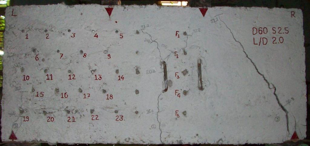
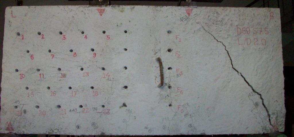
3 P P P P Elliptical Stress Pattern ELLIPTICAL STRESS PATTERN IN MODERATE DEEP BEAM Compressive Stress Trajectories PATH OF COMPRESSIVE STRESS TRAJECTORIES IN MODERATE DEEP BEAM Figure 1: Concept of stress distribution in moderate deep beam There were four series of beams having different depths of 300 mm, 400 mm, 500 mm, and 600 mm and each series comprised of four beams on which the axial concrete strain was measured on surface planes situated at different depths of 0.0 cm (i.e., at the surface), 2.5 cm, 5.0 cm, and 7.5 cm across the width of the beams. The beam notation D50 S 2.5 denotes the beam having overall depth D of 50 cm and axial concrete strain measured on surface plane situated at a depth of 2.5 cm across the width of the beam. LO A D PO INT F O RM BEA M DIAL G AUG ES 3.3 Testing Procedure Figure 2: Test setup All the beams were tested under two point concentrated loadings positioned at one third spans. All the beams were simply supported with a effective span of 1200 mm. Beams were centered on platform and leveled horizontally and vertically by adjusting the bearing plates. Load was applied gradually. Three dial gauges were used to measure the deflection at the center and under the points of loadings. Here, Delta rosette is used for measuring strains at different demec points in which three strains are required to calculate the shear strains and shear stresses. In D30 and D40 beams demec targets numbers are 6,7,8 and in D50 and D60 beams demec targets numbers are 7,8,11,12,13,16,17. Readings were taken at proper load interval. Deflections, concrete surface strains and in depth strains in flexure and shear zones were measured using mechanical strain gauge. Crack propagations were traced by pencil and their tips were marked corresponding to the load readings. 246
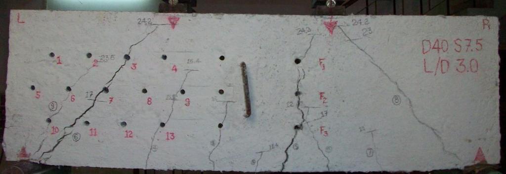
4 BEAMS OF SERIES D30 & D BEAMS OF SERIES D50 & D60 Figure 3: Hexagonal grid arrangements of demectargets 4. Discussion of Test Result 4.1 Crack Patterns, Propagation, and Modes of Failure In all the beam specimens, initiation of flexure cracks (Fig 4) was from the bottom of the beams. In most of the cases, all the flexure cracks were almost vertical, while most of the shear cracks (Figure 4) were inclined and their direction of propagation was towards the nearest load point irrespective of its place of origin. Beams of series D30 and D40 failed in pure flexure failure by yielding of longitudinal tensile reinforcement. Size and propagation of the flexure cracks were noticeable, while shear cracks 3 were few and very fine. Majority of flexure cracks (Figure 4) propagated beyond 4 height of the beam and were considerably wide at the bottom. Beams of series D50 failed in flexureshear mode. The phenomenon of all of a sudden formation of major diagonal shear cracks D D emerging from 3 to 4 height of the beam from bottom and its rapid propagation towards the nearest load and support point; was firstly seen in beams of D50 series. Although, the shear cracks were comparable to flexure cracks; the ultimate failure of all the beams of D50 series was due to the yielding of the longitudinal tensile reinforcement. Beams of series D60 failed in pure shear failure. Flexure cracks were few and very fine, and hardly reached up to the mid height of the beam, while shear cracks were noticeable in size and its propagation 3 covered more than 4 height of the beam. After sudden formation of major diagonal shear cracks (Figure 4) beam sustained some more load before ultimate failure, which shows its reserve strength. 247
 D30")
 D40")
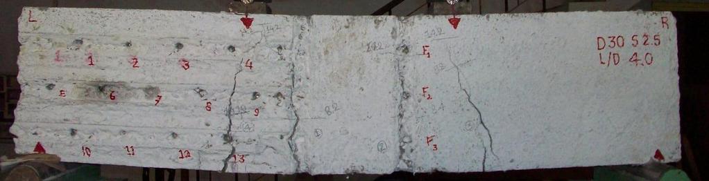

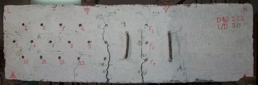
5 Figure 4: (a) D30 specimen Figure 4: (b) D40 specimen 248
 D50")
 D60")
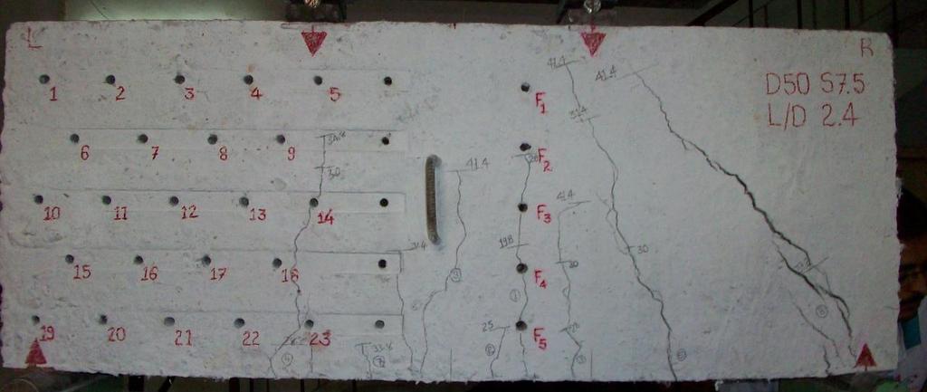

6 Figure 4: (c) D50 specimen Figure 4: (d) D60 specimen 249
7 250
8 5. Conclusion Figure 5: Principal strain distributions In majority of beams of series D50 and D60; the major diagonal shear cracks were formed all of a sudden. These cracks were initiated by splitting action and the phenomenon of failure was similar to that of cylinder under diametrical compression in split cylinder test. These D D cracks were emerged from 3 to 4 height of the beam from bottom and rapidly extended towards nearest load and support points. The plots (Fig 5) of evaluated results of principal tensile strain along the inclined axes in the vicinity of the diagonal shear cracks formed along the line joining the load and support points reveals the strain distribution similar to the elliptical pattern. Graphs (Fig 5) were plotted assuming a zero value of principal tensile strain at the top and bottom most edges of the beams. This phenomenon is consistent with the theoretical and experimental observations reported by others. 251
9 6. References 1. Kong, F. K., Reinforced Concrete Deep Beams, first edition, Blackies and son Ltd., Glasgow and London, Published by van Nostrand Reinhold, New York, June Kotsovos, Michael D., Behavior of Reinforced Concrete Beams with a shear span to Depth Ratio Between 1.0 and 2.5, Title no , ACI Journal, V. 81, No. 3, May June 1984, pp Patel, S. N., and Damle, S. K., Behavior of Reinforced Concrete deep Beams in flexure and shear, PhD Thesis, The M. S. University of Baroda, December Ramkrishnan. V. and Ananthnarayana. Y., Ultimate Strength of Deep Beams in Shear, ACI Journal Proceedings, V.65, No.2, February