Best practice specification, design and installation for post-installed anchors in safety-critical applications
|
|
|
- Elaine Oliver
- 5 years ago
- Views:
Transcription
1 Best practice specification, design and installation for post-installed anchors in safety-critical applications Dr. Jessey Lee Dr. David Heath Prof. Emad Gad 1
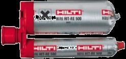
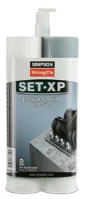
2 KEY TAKE-AWAY POINTS TS 101 is for safety-critical applications only Concrete is assumed to be cracked unless proven otherwise Not all chemical anchors are the same, particularly under sustained loading applications not all chemicals are suitable for sustained loading applications. For e.g. in uncracked concrete, a polyester may have bond strength in the range of 5 9 MPa while an epoxy may have bond strength in the range of MPa For quality assurance of safety critical applications, require: Product prequalification Design as per TS 101 Installation by qualified installers 2
3 OUTLINE Australian Engineered Fasteners and Anchors Council Anchor types and safety-critical applications Prequalification Design methodology Installation Case study Summary & acknowledgements 3


4 AUSTRALIAN ENGINEERED FASTENERS & ANCHORS COUNCIL


5 AEFAC FOUNDING BOARD MEMBERS AEFAC SUPPORTING MEMBERS 5

6 AUSTRALIAN ENGINEERED FASTENERS AND ANCHORS COUNCIL Guidelines for the specification of anchors For Designers Training & certification for installers of anchors For Contractors Minimum performance & standard specification For Manufacturers AEFAC Guideline for field testing & certification of anchors For Field Engineers Research & Development For anchor industry 6

7 SAFETY-CRITICAL APPLICATIONS & TYPES OF ANCHORS 7
8 Fastening for safety-critical applications A fastening whose failure may result in collapse or partial collapse of the structure, endanger human life and/or cause considerable economic loss. 8
9 APPLICATIONS Nonstructural Facades Suspended ceilings Heating & ventilation Pipelines Mechanical equip. Etc. Structural Structural connections Strengthening Eligehausen (University of Stuttgart) 9


10 Types of anchors: Post installed anchors Cast in anchors 10


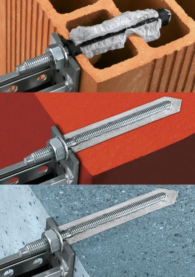
11 Post-installed applications: steel to concrete connections


12 Post-installed applications: concrete to concrete connections

13 CAST IN PLACE ANCHORS 13


14 WHAT CAN GO WRONG WITH ANCHORS? Street awning collapse in Queensland 1 fatality, 5 injuries Source: Workplace Health and Safety Queensland 14

")


15 WHAT CAN GO WRONG WITH ANCHORS? Boston Big Dig Tunnel, 2006 Source: NTSB (2007) Highway Accident Report, Ceiling collapse in the Interstate 90 Connector Tunnel, Boston, Massachusetts, July 10,


16 WHAT CAN GO WRONG WITH ANCHORS? Typical chemical anchor and roof hanger plate assembly. Photograph taken following incident showing roof hangers pulled away from tunnel roof. Source: Brady, S., Interstate 90 Connector Tunnel ceiling collapse The Structural Engineer, April 2013 Boston Big Dig Tunnel, 2006 Source: NTSB (2007) Highway Accident Report, Ceiling collapse in the Interstate 90 Connector Tunnel, Boston, Massachusetts, July 10, 2006 Three of the 20 failed anchors taken from the site of the incident illustrating defects. 16
17 SAFETY-CRITICAL APPLICATIONS Three critical elements to achieve quality assurance 1. PREQUALIFICATION Products independently assessed to be fit for purpose 2. DESIGN Rigorous assessment to design for critical mode of failure 3. INSTALLATION Informed and competent installer with appropriate supervision and experience 17
18 PREQUALIFICATION SA TS101:2015 APPENDIX B
19 PREQUALIFICATION Identification tests is product fully traceable and does it meet product specifications? Suitability tests is the product suitable for its intended application? Admissible service condition tests will the product perform for its service life? 19
20 PREQUALIFICATION IN TS101 Two approaches for prequalification: 1. Testing and assessment in accordance with Appendix B Testing in accordance with ETAG001 parts 1 to 5 or EAD as applicable and assessment as outlined in Appendix B Or 2. European Technical Assessment (ETA) A current ETA satisfies the relevant testing and assessment requirements as outlined in Appendix B 20
21 SAFETY-CRITICAL ANCHORS Three critical elements to achieve quality assurance 1. PREQUALIFICATION Products independently assessed to be fit for purpose 2. DESIGN Rigorous assessment to design for critical mode of failure 3. INSTALLATION Informed and competent installer with appropriate supervision and experience 21
22 SA TS DESIGN OF POST-INSTALLED AND CAST-IN FASTENINGS FOR USE IN CONCRETE 22

(iii) NCC Volume Two Clause 3.11.")
23 SA TS Deemed-to-satisfy provisions Primary reference in 2016 NCC: NCC Volume One Clause B1.4(b)(iii) NCC Volume Two Clause (f)(iii) 23
24 SA TS NCC SA TS 101 (Deem-to-Satisfy) ALTERNATIVE SOLUTION PREQUALIFICATION (APPENDIX B) AEFAC Installer Certification Program (RECOMMENDED) TEST & ASSESS (APPENDIX B) (ETAG & EAD) ETA 24


25 SA TS Overview Based on European guidelines Compatible with products prequalified through Appendix B Scope safety-critical fasteners Post-installed Mechanical anchors Chemical anchors Cast-in Anchor channel 25
26 SA TS Exclusions Design for exposure to fire, durability and seismic actions Design of fixtures Design of fasteners for lifting, transport and erection (brace inserts, lifting inserts, etc.) Headed fasteners Ferrules Reinforcement for development length considerations Headed reinforcement Anchorage for prestressing strands 26
27 SA TS Determination of forces acting on fasteners Load sharing among fasteners Eccentricity in a fastener group Influence of edges Influence of a lever arm Influence of fixture plate Load resisted by supplementary reinforcement (if present) 27
28 SA TS Permissible configurations of fastenings: a) Configurations of fasteners close to an edge (c i < max(10h ef, 60d nom )), tension only b) Configurations of fasteners remote from edges (c i max(10h ef, 60d nom )), all load directions c) Configurations of fasteners close to an edge (c i < max(10h ef, 60d nom )), all load directions 28

29 TS 101: CRACKED CONCRETE Limited to maximum crack width of 0.3 mm Concrete assumed to be CRACKED in design unless proven otherwise. Note: Not all products can be used in cracked concrete!! SA TS 101: FAQ ( 29
30 TENSION SA TS ANCHOR FRACTURE CONCRETE CONE PULL-OUT CONE & PULL- OUT SPLITTING BLOW-OUT ANCHOR BOLT FRACTURE CHANNEL LIP CHANNEL FLEXURE ANCHOR/ CHANNEL CONNECTION SUPPLEMENTARY REINFORCEMENT FRACTURE SUPPLEMENTARY REINFORCEMENT 30 ANCHORAGE FAILURE 30

")

")


31 SHEAR SA TS FRACTURE (NO LEVER ARM) BENDING (LEVER ARM) EDGE FAILURE PRYOUT FAILURE (a) FRACTURE (b) ANCHORAGE SUPPLEMENTARY REO. 31 FRACTURE (NO LEVER ARM) BENDING (LEVER ARM) ANCHOR FRACTURE ANCHOR/ LIP FLEXURE EDGE CHANNEL FAILURE CONNECT. PRYOUT FAILURE SUPPLEMENTARY REO. 31
32 SA TS : SHEAR LOADS DISTRIBUTION CLOSE TO AN EDGE Shear load parallel to edge Shear load perpendicular to edge (only 2 fasteners closest to edge considered) 32


33 COMBINED SA TS Steel failure bolt failure Steel failure anchor channel modes Other failure modes Supplementary reinforcement 33
34 SA TS : DESIGN METHODOLOGY Example: Concrete cone failure mode (tension) A A A 0 c, N N Rk, c N Rk, c 0 s, N re, N ec, N M, N A c, N 0 N Rk,c c, N 0 c, N s,n re,n ec,n M,N k Inverted rectilinear pyramid characteristic concrete cone strength (no spacing effects, edge effects, etc f ' c hef adjustment for effects of fastener spacing and edge effects (can the full inverted rectilinear pyramid cone form?) factor accounting for disturbance of stresses in concrete due to an edge factor accounting for a dense layer of reinforcement in concrete factor accounting for different tension loads on fasteners in a group subjected to eccentric loading factor accounting for the influence of a compression force between the fixture and concrete when a bending moment is present Cross-section Plan view NB: Still need to consider other potential modes of failure to determine decisive failure mode!

 Include prequalified products (i.e. ETA) Compatible with TS 101 (with conversion)")
35 SA TS : DESIGN METHODOLOGY Software Freely available from reputable manufacturers Rapidly solve complex designs (minutes vs. hours/days!) Include prequalified products (i.e. ETA) Compatible with TS 101 (with conversion)


36 SA TS : DESIGN SOFTWARE List of software that design to SA TS 101 / ETAG Ramset iexpert TM Hilti - PROFIS Wurth Technical Software Powers Design Assist Simpson Strong Tie Anchor Designer Free download on website 36

37 SA TS : FAO Refer to AEFAC s website for FREQUENTLY ASKED QUESTIONS on SA TS
38 SAFETY-CRITICAL ANCHORS Three critical elements to achieve quality assurance 1. PREQUALIFICATION Products independently assessed to be fit for purpose 2. DESIGN Rigorous assessment to design for critical mode of failure 3. INSTALLATION Informed and competent installer with appropriate supervision and experience 38
39 AEFAC INSTALLER CERTIFICATION PROGRAM 39

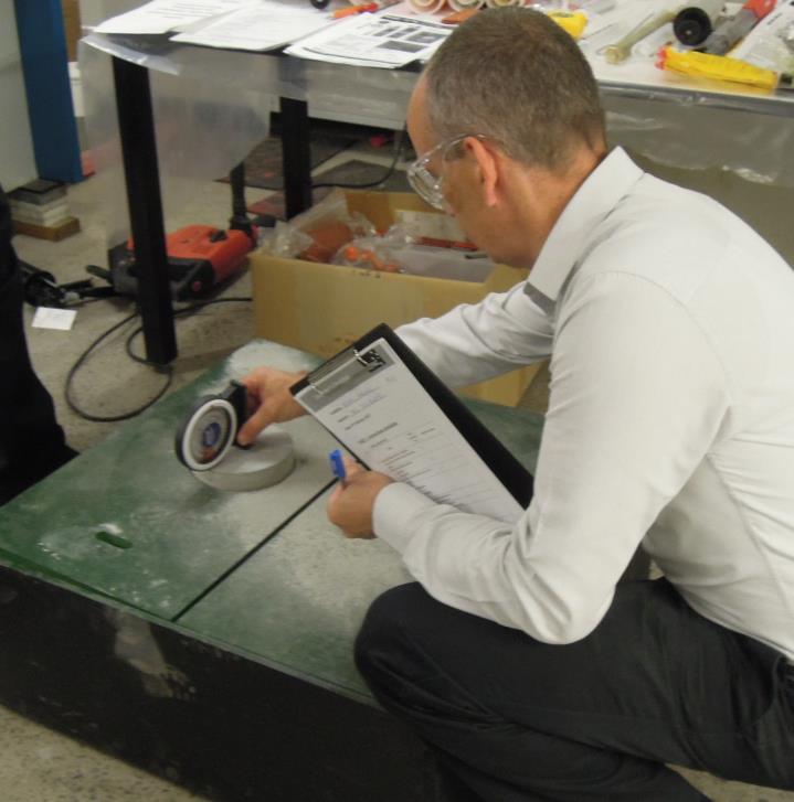
40 AEFAC INSTALLER CERTIFICATION PROGRAM The best product is only as good as its installation Correct installation is imperative to ensure the designer s intent is met Until now, performed on an ad-hoc basis job dependent, product specific Reasonable errors acceptable, gross errors dangerous Combination of appropriate training and supervision critical Clear need for a program to provide: Written and practical test How to correctly drill How to correctly prepare a hole Understanding anchor systems Understanding risks of errors 40

41 INSTALLER CERTIFICATION PROGRAM 41

42 AEFAC INSTALLER CERTIFICATION PROGRAM Importance of hole cleanliness Drill dust will prevent proper bonding -> Strength reduction! Well-cleaned Poorly cleaned Courtesy of IWB, University of Stuttgart 42
43 Bond Strength, % AEFAC INSTALLER CERTIFICATION PROGRAM Sensitivity to cleaning method Drill dust will prevent proper bonding -> Strength reduction! Method of hole cleaning 1 2xblowing, 2xbrushing, 2xblowing 2 1xblowing, 1xbrushing 1xblowing 3 2xblowing Method of Hole Cleaning 4 No cleaning (drilling machine retracted 3 times) 43


44 AEFAC INSTALLER CERTIFICATION PROGRAM Written examination Training Face to face training, Installer Training Manual Practical examination Part 1: Vertical down installation Part 2: Overhead injection Certification awarded *This program is based on the US ACI- CRSI Adhesive Anchor Installer Program modified for Australian practice Recertification period Initial: Three years Additional: Every five years 44

45 AEFAC INSTALLER CERTIFICATION PROGRAM Important note: By completing certification, you have demonstrated that you understood the risks involved in poor installation practices Abide to the AEFAC Installer Code of Conduct Failure to comply after certification awarded Certification status revoked Potential legal implications! Certified Installer Card awarded & registration on AEFAC s website 45


46 AEFAC INSTALLER CERTIFICATION PROGRAM 46


47 AEFAC INSTALLER CERTIFICATION PROGRAM 47


48 INSTALLER CERTIFICATION PROGRAM OVERHEAD INJECTION 48


49 INSTALLER CERTIFICATION PROGRAM OVERHEAD INJECTION 49


50 But I ve been doing it this way for years!

51 AEFAC TECHNICAL NOTE ENGINEERING GENERAL NOTES OCUMENTS/AEFAC-TN-ENG- GEN-NOTES.PDF 51

52 AEFAC TECHNICAL NOTE ENGINEERING GENERAL NOTES 52
53 AEFAC ENGINEERING GENERAL NOTES Proposed notes for contract drawings 53
54 SUMMARY & ACKNOWLEDGEMENTS Anchor industry is safety-critical. Anchor failures should not happen they do! AEFAC has created a body of knowledge and expertise to introduce governance to the Australian anchor industry Satisfactory anchor performance is achieved from: i) appropriate product prequalification, ii) robust design, and iii) correct installation. TS 101 provides a consistent and robust approach to anchor design based on best practice The AEFAC Installer Certification Program has been developed to equip installers with the skill to ensure that anchors are installed as intended 54

55 Website Overview of AEFAC AEFAC members Education events Technical Notes Sample Specifications Installer Certification TS 101: FAQ Links to resources SUMMARY & ACKNOWLEDGEMENTS 55


56 SUMMARY & ACKNOWLEDGEMENTS Founding Board Members Supporting Members 56