Seismic Steel Design 12/9/2012
|
|
|
- Hope Lane
- 5 years ago
- Views:
Transcription


1 Chapter 8 Design of Seismic-Resistant Steel Building Structures: A Brief Overview SEISMIC STEEL DESIGN IN CANADA and the USA Instructor: Dr. Carlos E. Ventura, P.Eng. Department of Civil Engineering The University of British Columbia CANADA ventura@civil.ubc.ca Earthquake Effects on Structures Importance of Ductility Design Earthquake Forces Steel Seismic Load Resisting Systems Seismic Provisions Concluding remarks Structural Steel in Buildings Building Acceleration Building: Mass = m Ground Acceleration From Canadian Institute of Steel Construction 09/12/ H F = ma Earthquake Forces on Buildings: Inertia Force Due to Accelerating Mass H Ductility = Inelastic Deformation by Dr. Carlos E. Ventura, UBC 1
2 H H Ductility in Steel Structures: Yielding Nonductile Failure Modes: Fracture or Instability yield failure Ductility Factor μ = failure yield H Ductility = Yielding Failure = Fracture or Instability Developing Ductile Behavior: Choose frame elements ("fuses") that will yield in an earthquake. Detail "fuses" to sustain large inelastic deformations prior to the onset of fracture or instability (i.e., detail fuses for ductility). Design all other frame elements to be stronger than the fuses, i.e., design all other frame elements to develop the plastic capacity of the fuses. Design EQ Loads Total Lateral Force: V CW s V = total design lateral force or shear at base of structure W = effective seismic weight of building C S = seismic response coefficient V Basic Concept Seismic Design Philosophy Impractical to design a structure to withstand seismic force in elastic range Allow the structure go into the inelastic deformation to absorb energy Simplification: come up with R factor design approach (Engineers only need to do elastic analysis with an assumed R value) Determine the static force using NBCC 10 and the ductility requirement by CSA-S16 09/12/ Design Earthquake Loads NBCC 2010: V = S M v I E W R d R o S : Design Spectral Acceleration (2%-50yrs) M v : Higher modes I E : Importance factor W : Seismic weight R d : Ductility-related FMF Force Modification Factors (FMF): R o : Overstrength-related FMF SFRS: R d R o R d R o Ductile Steel MRF: Type MD Steel CBF: Type CC Steel SFRS: R. Tremblay, Ecole Polytechnique of Montreal 12 by Dr. Carlos E. Ventura, UBC 2
3 Ductility-related force modification factor (R d ): This factor corresponds to the R factor used in the previous 1995 edition. For steel structures, these have been increased for ductile and moderately ductile systems to 3.5 and 5.0, compared to 3.0 and 4.0 in the previous code. The design forces for these systems are now lower; however, the details requirements to ensure adequate ductility according to these factors are more demanding. Force reduction factors in the 2010 NBCC Overstrength-related force modification factor (R o ): This factor is related to the calibration factor U used in the previous code. It takes into account in a more explicit way the overstrength in structures, by identifying the sources of it and assigning factors that consider each of these sources, like the actual strength of the material, rounding up of dimensions of the elements, and redistribution of internal forces. V V e x 1.5 R or d = 1.3 R or d = 1.95 Plastic Def. e 1.5 e 09/12/ R. Tremblay, Ecole Polytechnique of Montreal 14 Steel seismic force resisting systems (SFRS) Design EQ Loads Total Lateral Force per ASCE 7-05: V C W S Characteristics of SFRS: The 2010 NBCC recognizes different types of SFRS, their corresponding R d and R o factors, and the design and detail requirements for each of them according to the CSA standard CSA-S In each of these SFRS, there are certain structural elements which are designed to dissipate energy by inelastic deformation; these must be able to sustain various cycles of inelastic loading with a minimum reduction of strength and stiffness. The other elements and connections must respond elastically to loads induced by yielding elements. Classification of SFRS according to there ductile behavior: Ductile or Type D: They can sustain severe inelastic deformations. They have a force reduction factor between 4.0 and 5.0. Moderately ductile or Type MD: Inelastic deformations are more limited, members are designed to resist greater loads. They have a force reduction factor between 3.0 and 3.5. Limited ductile or Type LD: These are newly introduced types of frames. Inelastic deformations are even more limited and design loads are greater than in type MD elements. They have a force reduction factor of /12/ SDS CS R I S DS = design spectral acceleration at short periods S D1 = design spectral acceleration at 1-second period S D1 R T I SD1T L 2 R T I I = importance factor for T T L for T > T L T = fundamental period of building T L = long period transition period R = response modification coefficient R factors for Selected Steel Systems (ASCE 7): Seismic Load Resisting Systems for Steel Buildings SMF (Special Moment Resisting Frames): R = 8 IMF (Intermediate Moment Resisting Frames): R = 4.5 OMF (Ordinary Moment Resisting Frames): R = 3.5 EBF (Eccentrically Braced Frames): R = 8 or 7 SCBF (Special Concentrically Braced Frames): R = 6 OCBF (Ordinary Concentrically Braced Frames): R = 3.25 BRBF (Buckling Restrained Braced Frame): R = 8 or 7 SPSW (Special Plate Shear Walls): R = 7 Moment Resisting Frames Concentrically Braced Frames Eccentrically Braced Frames Buckling Restrained Braced Frames Special Plate Shear Walls Undetailed Steel Systems in Seismic Design Categories A, B or C R = 3 (AISC Seismic Provisions not needed) by Dr. Carlos E. Ventura, UBC 3
 27.")


4 Clause 27 of CSA-S16-01 Seismic design requirements Research Northridge 1994 Kobe 1995 SIGNIFICANT REVISIONS 9 December December MOMENT RESISTING FRAME (MRF) 27. Seismic Design Requirements Capacity Design: Specific elements or mechanisms are designed to dissipate energy; All other elements are sufficiently strong for this energy dissipation to be achieved; Structural integrity is maintained; Elements and connections in the horizontal and vertical load paths are designed to resist these seismic loads; Diaphragms and collector elements are capable of transmitting the loads developed at each level to the vertical lateral-load-resisting system; and, These loads are transmitted to the foundation. 9 December Beams and columns with moment resisting connections; resist lateral forces by flexure and shear in beams and columns - i.e. by frame action. Develop ductility primarily by flexural yielding of the beams: Advantages Architectural Versatility High Ductility and Safety Disadvantages Low Elastic Stiffness Moment Resisting Frame by Dr. Carlos E. Ventura, UBC 4

 Type LD ( frames with limited ductility, R = 2 ) 9 December 2012 28 Type D & Type MD")
 Moment Connections for Seismic Applications by CISC 9 December 2012 29 Reduced beam")
5 Inelastic Response of a Steel Moment Resisting Frame 27. Seismic Design Requirements Moment-Resisting Frames Type D (ductile moment-resisting frames, R = 5 ) Type MD (moderately ductile, R = 3.5 ) Type LD ( frames with limited ductility, R = 2 ) 9 December Type D & Type MD - Inelastic Response PLASTIC HINGE (typ.) Moment Connections for Seismic Applications by CISC 9 December Reduced beam section 9 December 2012 Bolted end plate - 8 bolts Bolted stiffened end plate 16 bolts 30 by Dr. Carlos E. Ventura, UBC 5


 - reduced architectural")
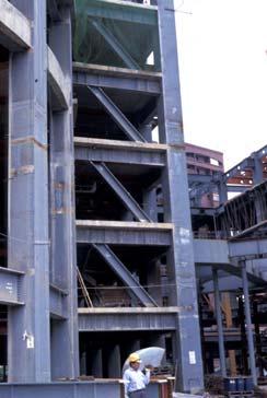
6 Concentrically Braced Frames (CBFs) Beams, columns and braces arranged to form a vertical truss. Resist lateral earthquake forces by truss action. Types of CBFs Develop ductility through inelastic action in braces. - braces yield in tension - braces buckle in compression Advantages - high elastic stiffness Disadvantages - less ductile than other systems (SMFs, EBFs, BRBFs) - reduced architectural versatility Single Diagonal Inverted V- Bracing V- Bracing X- Bracing Two Story X- Bracing by Dr. Carlos E. Ventura, UBC 6
 Compression Brace (previously in tension): Buckles (nonductile) Tension Brace (previously in compression): Yields (ductile)")
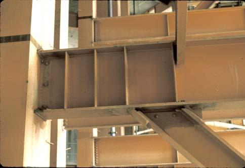
7 Inelastic Response of CBFs under Earthquake Loading Inelastic Response of CBFs under Earthquake Loading Inelastic Response of CBFs under Earthquake Loading Tension Brace: Yields (ductile) Columns and beams: remain essentially elastic Compression Brace: Buckles (nonductile) Compression Brace (previously in tension): Buckles (nonductile) Tension Brace (previously in compression): Yields (ductile) Columns and beams: remain essentially elastic Eccentrically Braced Frames (EBFs) e Link Framing system with beam, columns and braces. At least one end of every brace is connected to isolate a segment of the beam called a link. Resist lateral load through a combination of frame action and truss action. EBFs can be viewed as a hybrid system between moment frames and concentrically braced frames. Develop ductility through inelastic action in the links. EBFs can supply high levels of ductility (similar to MRFs), but can also provide high levels of elastic stiffness (similar to CBFs) e Link by Dr. Carlos E. Ventura, UBC 7


8 e Link Some possible bracing arrangement for EBFS e e e e e Link e e by Dr. Carlos E. Ventura, UBC 8


9 Inelastic Response of EBFs Concentrically Braced Frames Type MD (Moderately Ductile) R = 3.0 Type LD (Limited-Ductility) R = 2.0 Tension yielding (typ.) Inelastic buckling with plastic hinge (typ.) 9 December by Dr. Carlos E. Ventura, UBC 9
 Rotation: Allow rotation to develop upon buckling, or Design for 1.")


10 Type MD - Brace Connections Design Brace Axial Forces: Tension = R y A F y Compression 1.2 C u 27. Seismic Design Requirements Ductile Eccentrically Braced Frames ( R = 4.0 ) Rotation: Allow rotation to develop upon buckling, or Design for 1.1 R y M pb Energy dissipation through yielding in links: shear or bending 9 December December Eccentrically Braced Frames Higher capacity for stiffener welds Link beam to column connections: Min. rotation capacity Detailing Columns Higher loads in top 2 floors Moments included in design Splices designed for shear L 9 December p = p L/e Buckling-Restrained Braced Frames (BRBFs) Type of concentrically braced frame. Beams, columns and braces arranged to form a vertical truss. Resist lateral earthquake forces by truss action. Special type of brace members used: Buckling-Restrained Braces (BRBs). BRBS yield both in tension and compression - no buckling!! Develop ductility through inelastic action (cyclic tension and compression yielding) in BRBs. System combines high stiffness with high ductility. Buckling-Restrained Brace Buckling-Restrained Brace Buckling- Restrained Brace: Steel Core + Casing A A Buckling- Restrained Brace: Steel Core + Casing Casing Steel Core Casing Steel jacket Mortar Steel Core Debonding material Section A-A by Dr. Carlos E. Ventura, UBC 10


11 Buckling-Restrained Brace Buckling-Restrained Brace P P Buckling- Restrained Brace: Steel Core + Casing Steel Core Steel core resists entire axial force P Casing is debonded from steel core - casing does not resist axial force P - flexural stiffness of casing restrains buckling of core Yielding Segment Core projection and brace connection segment Bracing Configurations for BRBFs Single Diagonal Inverted V- Bracing V- Bracing X- Bracing Two Story X- Bracing by Dr. Carlos E. Ventura, UBC 11


12 Inelastic Response of BRBFs under Earthquake Loading Tension Brace: Yields Compression Brace: Yields Columns and beams: remain essentially elastic Special Plate Shear Walls (SPSW) Assemblage of consisting of rigid frame, infilled with thin steel plates. Under lateral load, system behaves similar to a plate girder. Wall plate buckles under diagonal compression and forms tension field. Develop ductility through tension yielding of wall plate along diagonal tension field. Compression Brace: Yields Tension Brace: Yields System combines high stiffness with high ductility. Columns and beams: remain essentially elastic by Dr. Carlos E. Ventura, UBC 12
 9 December 2012 73 9 December 2012 74 9")


13 27.10 Conventional Construction ( R = 1.5 ) 9 December December December December Background In comparison with moment-resisting frames or reinforced concrete shear wall systems, the use of steel plate shear panels has shown to be more cost-effective by: Reducing the amount of steel needed Increasing the available floor space Increasing the rate of structural steel erection Reducing foundation costs Decreasing dead weight while increasing the overall stiffness and reducing the drift of the structure 9 December by Dr. Carlos E. Ventura, UBC 13


14 9 December Plate-Girder Analogy 9 December Inelastic Response of a SPSW Development of tension diagonals R = 5 Shear buckling 9 December by Dr. Carlos E. Ventura, UBC 14
15 Plate Walls Type D (Ductile) R = 5.0 Type D - Detailing Yielding in web plates & plastic hinges in framing members: Type LD (Limited-Ductility) R = Clause 20 9 December December 2012 Steel plate (typ.) Splices: Full flexural capacity h s /4 1.5d c Rigid beam-to-column connections with ductile detailing Beams: Class 1 Columns: Class 1 Stiffened column base 86 Instructor: Dr. C.E. Ventura Conclusions An overall overview of the seismic design of steel structures in Canada and the US has been carried out. The design procedures for SFRS, moment-resisting connections, and some special framing systems, which are spread in various documents and publications, have all been organized in this report. Each of the SFRS presented have their own advantages and disadvantages. There may be cases in which it might not be possible to use the prequalified connections, and physical tests are usually very expensive and cannot be afforded by small engineering companies. More research is needed to develop design procedures for various types of connections with different element sections. Systems like the special truss moment frame and the frictiondamped steel frame provide safe and economic solutions compared to conventional framing systems, and may be implemented in future codes. Note: Several of the slides were kindly provided by Mr. Michael Gilmor, P.Eng., Vice President Operations of the Canadian Institute of Steel Construction, Dr. Mahmoud Rezai, P.Eng. of EQTECH and Prof. Michael D. Engelhardt of the University of Texas at Austin with the support of the American Institute of Steel Construction. 09/12/ No. 88 Instructor: Dr. C.E. Ventura The end No. 89 by Dr. Carlos E. Ventura, UBC 15