GEOTECHNICAL EXPLORATION REPORT
|
|
|
- Maria Lindsey
- 5 years ago
- Views:
Transcription


1
2 GEOTECHNICAL EXPLORATION REPORT LITTLE MIAMI WWTP STORM DRAIN REALIGNMENT CINCINNATI, HAMILTON COUNTY, OHIO MSDGC PROJECT NO PREPARED FOR: METROPOLITAN SEWER DISTRICT OF GREATER CINCINNATI 1600 GEST STREET CINCINNATI, OHIO 4204 PREPARED BY: CTL ENGINEERING, INC. 210 SCHAPPELLE LANE CINCINNATI, OHIO 4240 CTL PROJECT NO CIN MARCH 18, 201
3 Geotechnical Exploration Report March 18, 201 Little Miami WWTP Storm Drain Realignment CTL Project No CIN Cincinnati, Hamilton County, Ohio Page i TABLE OF CONTENTS PAGE I. PROJECT INFORMATION AND PURPOSE... 1 II. SUBSURFACE EXPLORATION... 1 III. FINDINGS... 2 A. Observations...2 B. Geology...2 C. Subsurface Conditions...3 D. Environmental Soil and Groundwater Sampling...4 IV. DISCUSSION AND EVALUATION... A. Trench Backfill, Compaction and Monitoring... B. Moderately to Highly Plastic Bearing Soils...6 C. Groundwater...6 V. ANALYSIS AND RECOMMENDATIONS... 6 A. Excavation...7 B. Groundwater Control...9 C. Pipe Support (Open-Cut Method)...9 VI. CHANGED CONDITIONS VII. TESTING AND OBSERVATION VIII. CLOSING APPENDIX A APPENDIX B APPENDIX C APPENDIX D TEST BORING RECORDS RESULTS OF SOIL LABORATORY TESTS BORING LOCATION PLAN RESULTS OF ANALYTICAL CHEMISTRY TESTS
4 Geotechnical Exploration Report March 18, 201 Little Miami WWTP Storm Drain Realignment CTL Project No CIN Cincinnati, Hamilton County, Ohio Page 1 I. PROJECT INFORMATION AND PURPOSE The Metropolitan Sewer District of Greater Cincinnati (MSDGC) is planning for the design and construction of replacement of manholes and storm sewer lines at the Little Miami Wastewater Treatment Plant (LMWWTP) in Cincinnati, Hamilton County, Ohio. In addition, MSDGC requested that CTL perform environmental sampling and analytical testing of the soil beneath for a mercury spill that occurred in this area in June The project is located within the parking area of the treatment plant and begins east of the incinerator building and continues in an easterly and southerly direction to the existing pump station wet well. CTL Engineering, Inc. (CTL) understands the purpose of this geotechnical exploration is to determine the subsurface conditions of the site in conjunction with evaluating its suitability for the installation of the new storm sewer. CTL was provided a set of plans prepared by the MSDGC and dated January 8, 201. The plans show the proposed alignment and profile of the new storm sewer and manholes, other underground utilities, existing site topographical features, and proposed test boring locations. These plans indicate that the proposed storm sewer will be installed at depths ranging from approximately 1 to 20 feet below ground surface (bgs). II. SUBSURFACE EXPLORATION Two (2) test borings, designated as TB-01 and TB-02, were drilled along the alignment of the proposed storm sewer at the locations shown on the boring location plan in Appendix C. The locations of the soil test borings were selected by MSDGC to provide a general profile of the subsurface conditions at the site. The test borings were drilled to predetermined depths according to MSDGC requirements. The test borings were located in the field by CTL personnel utilizing MSDGC survey points and topographic features identified on the plan and profile sheets. The test borings were drilled by CTL s drill crew on February 27, 201 utilizing hollowstem augers powered by a track-mounted drill rig. Standard Penetration Tests (SPTs) were conducted in the test borings using a 140-pound automatic hammer falling 30 inches to drive a 2-inch O.D. split barrel sampler for 18 inches. Standard penetration testing utilizing split-spoon sampling was performed continuously or at 2½-foot intervals. The environmental sampling field activities were conducted by Mr. Matt McClelland, Environmental Scientist, concurrently with the geotechnical exploration on February 27, 201. Soil samples obtained from the drilling operations were preserved in glass jars, visually classified in the field, and delivered to CTL s soil laboratory for classification, testing and analysis. Drilling, sampling, field and soil laboratory testing were performed according to standard geotechnical engineering practices and current ASTM procedures. Results from field and
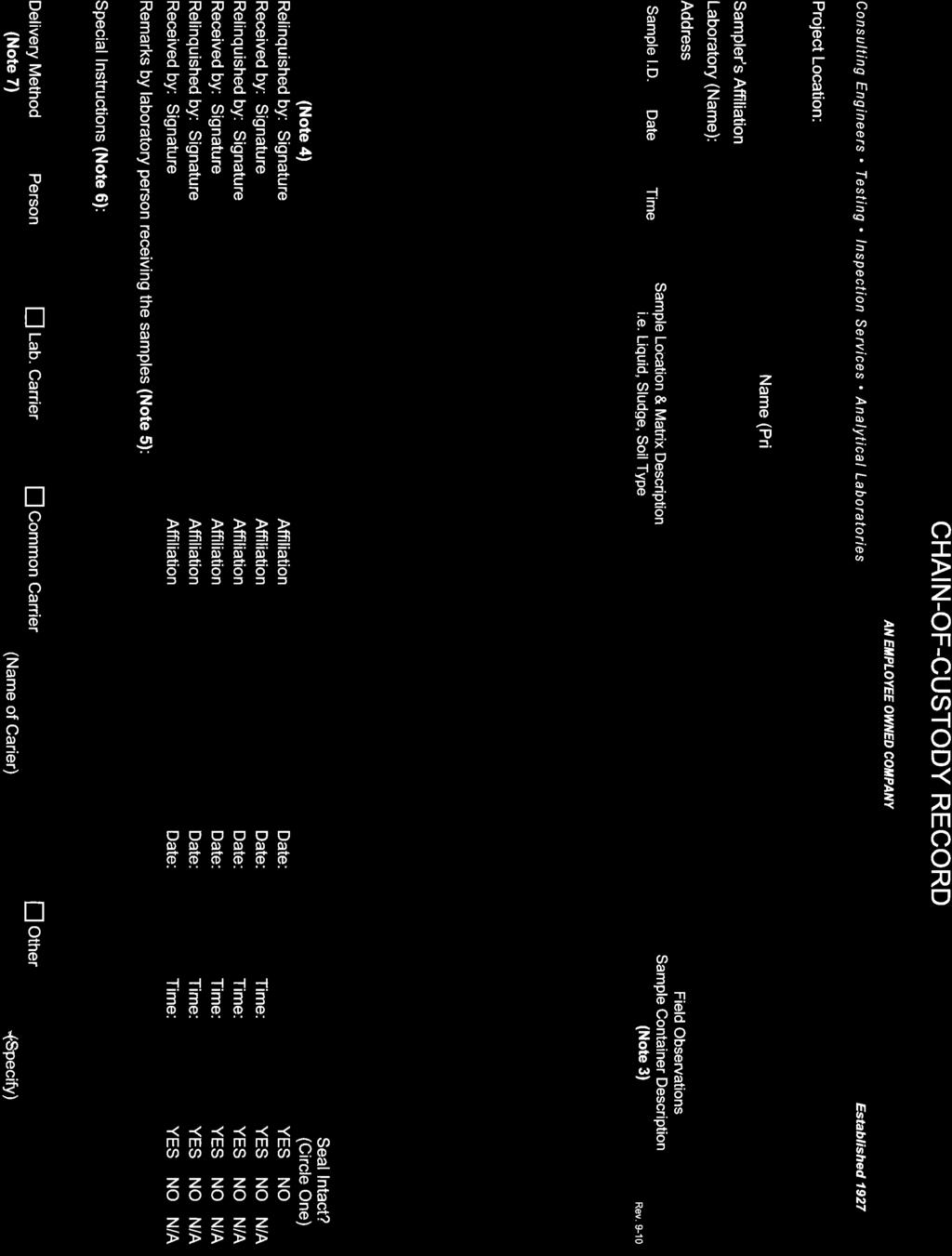
5 Geotechnical Exploration Report March 18, 201 Little Miami WWTP Storm Drain Realignment CTL Project No CIN Cincinnati, Hamilton County, Ohio Page 2 soil laboratory tests are shown on the enclosed test boring records in Appendix A. The results of the laboratory tests are presented in Appendix B. For the environmental soil samples, additional observations were recorded including the moisture content, presence of foreign material, unusual odors, and/or discoloration. Representative portions of soil were removed and placed in a 4-oz. glass sample jars, while minimizing vapor headspace. The jars were then capped using a Teflon-lined lid, labeled, recorded onto a chain-of-custody form, and placed in an iced cooler for potential laboratory analysis. Chain-of-custody documentation and laboratory analytical results are provided with the laboratory test results in Appendix D. III. FINDINGS A. Observations The subject site is located in existing parking lot and drive area within the Little Miami Wastewater Treatment Plant property. The ground surface is relatively flat in this area. The site plan indicates that sanitary sewers, water lines, electric lines, and a natural gas main are located underground within the project area. Based on available topographic mapping of the site (Newport Quadrangle, Ohio- Kentucky 7½-minute Series, USGS, 1961, Revised 1981), the topography is flat within the project area. The ground surface elevation is approximately 480 feet above mean sea level. B. Geology According to the Web Soil Survey: Hamilton County, Ohio (OH061), United States Department of Agriculture, Natural Resources Conservation Service, the surficial soils at the project site are identified as the Urban land- Udorthents complex, 0 to 12 percent slopes, occasionally flooded (UrUXCO). Due to the high percentage of urban land in this soil map unit, specific information regarding surficial soil properties is not available. Mapping of the bedrock topography ( Bedrock Topography of the Newport, Ky.- Ohio Quadrangle, Open-File Map BT-3B, ODNR Geological Survey, 1998), indicates the elevation of the top of rock surface in the immediate project area is between about 30 feet and 400 feet AMSL. These elevations correlate to approximate depths to the top of the bedrock surface ranging from about 80 feet to 130 feet below ground surface (bgs). It should be noted that the referenced mapping utilizes 0-foot contours that are interpolated from topographic surface features and widely spaced data points where water wells and soil borings have encountered rock.
6 Geotechnical Exploration Report March 18, 201 Little Miami WWTP Storm Drain Realignment CTL Project No CIN Cincinnati, Hamilton County, Ohio Page 3 According to the mapping of bedrock geology in the area, ( Reconnaissance Bedrock Geology of the Newport, Ky.-Ohio Quadrangle, Open-File Map BG-2, ODNR Geological Survey, February 2002), the surficial soil deposits are underlain by Ordovician-age sedimentary rock. Specifically, the bedrock underlying the site is identified as the Point Pleasant Formation. This formation consists of interbedded shale and limestone, averaging 60 percent limestone and 40 percent shale. The rock is described as gray to bluish gray and weathers to light gray, with thin to medium bedding which can be planar to lenticular. According to the mapping of karst features in the area (Known and Probable Karst in Ohio, Map EG-1, Revised September 2002, ODNR Geological Survey), the project area is not located in or near a probable karst area or an area of carbonate-dominant lithology. C. Subsurface Conditions Further details of the subsurface conditions encountered during CTL s geotechnical exploration are presented on the test boring records in Appendix A. 1. Surficial Materials Both test borings encountered concrete pavement at the surface, with a thickness of about 6 inches. 2. Moderately to Highly Plastic Fine-Grained Soils Beneath the surficial materials, moderately to highly plastic fine-grained (silt and clay) soils were encountered in both test borings. These materials were visually described as medium stiff to very stiff, brown, brown and/or gray, lean clay, lean clay with sand, fat clay, and sandy fat clay. These materials were classified as CL or CH according to the Unified Soil Classification System (USCS). SPT N 60 -values determined within these materials ranged from to 18 blows per foot (bpf), with an average value of about 14 bpf. The N 60 -value is the SPT blow count corrected for the hammer efficiency delivered by the hammer system utilized, normalized to 60 percent efficiency in bpf. Selected samples of the moderately to highly plastic soils were tested in the laboratory for moisture content, Atterberg Limits and particle size analysis. The results of these tests are presented in Appendix B and are summarized here. The natural moisture content values of these materials ranged from 17 to 27 percent, with an average value of about 24 percent. Representative samples of the clay materials had Liquid Limits (LL) ranging from 37 to 2 and Plasticity Indexes (PI) ranging from 14 to 26. These materials were
7 Geotechnical Exploration Report March 18, 201 Little Miami WWTP Storm Drain Realignment CTL Project No CIN Cincinnati, Hamilton County, Ohio Page 4 classified as CL (lean clay) and CH (fat clay) according to the USCS. CTL anticipates that the storm sewer bedding and structures will bear within the plastic soils. 3. Granular Soils Granular soils were encountered beneath the fine-grained soils in both borings, and also in boring TB-01 from about 1. feet to 4. feet bgs. These materials were described as loose to medium dense, brown, well graded sand with gravel, well-graded sand with silt, silty sand with gravel, and well-graded gravel with sand. These materials were classified as SW, SM, SW-SM, or GW according to the USCS. SPT N 60 -values determined within these materials ranged from to 24 blows per foot (bpf), with an average value of about 16 bpf. The natural moisture content of the granular soils ranged from to 17 percent, with an average value of 12.7 percent. 4. Ground Water The depth to ground water was recorded during drilling and after removing augers at the completion of drilling, prior to backfilling of the borehole. The boreholes were immediately backfilled due to safety and traffic requirements and therefore long-term water level readings were not obtained. Ground water was encountered during drilling at depths of about 22.0 feet and 30.0 bgs. At the completion of drilling, groundwater was encountered at depths of about 22.2 feet to 34. feet bgs. D. Environmental Soil and Groundwater Sampling The environmental sampling field activities were conducted by Mr. Matt McClelland, Environmental Scientist, with CTL concurrently with the geotechnical exploration on February 27, 201. Please note that the environmental soil and groundwater samples for boring TB-02 were obtained from an offset boring identified as TB-02A, approximately one foot from test boring TB-02. Although continuous soil samples were removed, examined, and collected at 2-foot intervals, only selected soil samples were submitted for environmental laboratory analysis from both of the soil borings. Of the ten environmental soil samples collected, six samples were submitted for laboratory analysis. Since the potential for any soil impact is due to a surface release of mercury, no odors or discoloration were apparent in any of the soil samples collected, and because mercury binds with soil and does not easily migrate downward, the three samples from each boring at shallow intervals (0.-2. bgs; bgs; and bgs) were selected for laboratory analysis of the RCRA Metal Total Mercury using EPA Method 7470.
8 Geotechnical Exploration Report March 18, 201 Little Miami WWTP Storm Drain Realignment CTL Project No CIN Cincinnati, Hamilton County, Ohio Page Total Mercury was not detected above the applicable analytical method detection limits in any of the soil samples analyzed. The detection limits are significantly less than the Ohio EPA s VAP Generic Numeric Direct-Contact Soil Standards for the most conservative Residential Land Use category of 3.1 mg/kg for total mercury. Groundwater was encountered at a depth of approximately 22 feet bgs in test boring TB-02 and therefore, in accordance with our work plan, one water sample from this boring was collected. The groundwater sample was collected directly from the borehole using a disposable bailer into an appropriate laboratory-cleaned environmental sampling container. The sample was submitted to the laboratory for the analysis of the RCRA Metal Total Mercury. Total Mercury was not detected above its analytical method detection limit in the one groundwater sample analyzed. The detection limit of mg/l is less than the Ohio EPA s VAP Generic Unrestricted Potable Use Standard (GUPUS) of mg/kg for total mercury. Based on the foregoing, it is CTL s technical opinion that neither the soil nor the groundwater at the areas investigated are impacted with Total Mercury. Based on the findings of the soil and groundwater sampling for Total Mercury, no further environmental assessment is warranted at this time, and no special disposal requirements appears to be necessary for the soil, groundwater and/or concrete that will need to be excavated and possibly disposed of as part of the proposed sewer realignment project. IV. DISCUSSION AND EVALUATION Based on the subsurface information collected from the test borings, CTL s evaluation is that the site is generally suitable for the installation of the proposed storm sewer and associated appurtenances. Stiff to very stiff lean clay materials will provide support for the sewer and manholes. However, conditions were encountered which pose a concern from a geotechnical and construction standpoint. These concerns and their implications are addressed below. A. Trench Backfill, Compaction and Monitoring Monitoring of earthwork operations, especially the placement of backfill and compaction operations will be critical to the successful performance of the storm sewer and also the overlying roadway pavement after construction. Installation of the sewer and manholes will require the placement and compaction of a significant volume of granular backfill. The placement of large volumes of fill can lead to excessive settlement during and after construction if not properly placed and compacted.
9 Geotechnical Exploration Report March 18, 201 Little Miami WWTP Storm Drain Realignment CTL Project No CIN Cincinnati, Hamilton County, Ohio Page 6 The use of controlled low strength material-controlled density fill (CLSM-CDF) as a backfill material may be preferred in areas where sewer trenches are deep, the sewer trench width is limited due to other utility conflicts, or the sewer trench is located within drives and roadways where traffic needs to be re-established within the same day. B. Moderately to Highly Plastic Bearing Soils Moderately to highly plastic soils classified as CL (lean clay) and CH (fat clay) according to the USCS were encountered at or near the proposed storm sewer invert elevation in both test borings. CTL anticipates that the storm sewer bedding will bear near or on the moderately to highly plastic soils for its entire length. These moderately to highly plastic soils are susceptible to volume change with variations in moisture content. Should these volume changes (due to wetting during construction occur near the new sewers, the resulting deformations can cause undesirable vertical movement. Construction planning should minimize exposure of these soils to excessive wetting or drying. It is anticipated that once construction is complete the soil moisture content at the proposed sewer depth will stabilize, assuming sewer exfiltration is controlled satisfactorily. C. Groundwater Based on our experience with the geology at this site, ground water conditions affecting construction projects are related to trapped or perched water that may occur in irregular, discontinuous zones within the soil overburden, and may also be present but were not identified on the test boring records, especially within granular layers or zones. In addition, ground water is also typically encountered at the soil-rock interface. When these water bearing strata are exposed in excavations, such as utility trenches, they can produce widely varying seepage durations and rates depending on recent rainfall activity and other hydrogeologic characteristics of the area. Therefore, the presence of ground water, and the elevations at which it is encountered, may vary from those measured at the time of drilling. These perched water sources are often not linked to the more continuous static groundwater encountered at greater depths, at the soil-bedrock interface, or deeper within the underlying sedimentary rock itself. V. ANALYSIS AND RECOMMENDATIONS Based upon the preceding considerations as well as the subsurface information obtained from the field and laboratory testing, the following recommendations are provided.
10 Geotechnical Exploration Report March 18, 201 Little Miami WWTP Storm Drain Realignment CTL Project No CIN Cincinnati, Hamilton County, Ohio Page 7 A. Excavation 1. CTL anticipates that existing soils at the site can be excavated using conventional excavation equipment. 2. Care should be taken while excavating adjacent to existing utilities, driveways, sidewalks, roadways or other structures so as not undermine the existing support of these facilities. The effect of the excavation on the adjacent structures should be considered and evaluated. Depending upon the type and size of the structure or underground utility and its foundation system, if applicable, along with the length of time the excavation will be open, underpinning of the structure or underground utility may be required. 3. Based on CTL s review of the plan and profile sheets it appears there are no significant movement-sensitive above-ground structures within the zone of influence of the sewer line excavation. However, if the sewer alignment is revised and movement-sensitive above ground structures are located within the zone of influence of the excavation, they should be monitored on a daily basis to evaluate the effect of the excavation and any dewatering, if required. Surface monitoring points consisting of steel bars embedded in concrete, to a minimum depth of 36 inches below existing grade, should be utilized. In addition, where horizontal deflections are considered critical to movement-sensitive utilities or structures, inclinometers should be installed, and a baseline reading performed a minimum of one week prior to construction. The inclinometer should be monitored at frequent intervals. Results of the monitoring should be provided to the Geotechnical Engineer on a daily basis. The Geotechnical Engineer should determine acceptable limits of lateral and vertical deflections prior to excavation. In the event that excessive lateral or vertical movement is noted, the Geotechnical Engineer should be notified immediately. 4. Temporary shoring systems, where required, should be designed by a Licensed Professional Engineer, registered in the state of Ohio, familiar with the design of earth retention systems. The design of the shoring system should also take into account loading adjacent to the excavation such as foundation or vehicular loads and soil stockpiles.. Temporary trench excavations in excess of 4.0 feet in depth should be sloped or shored in accordance with OSHA regulations. The majority of the soils in the upper 20 feet are classified as Soil Type A, however all granular soils are classified as Soil Type C. 6. In excavations that are 20 feet or less in depth, OSHA regulations allow ¾:1 slopes in soils classified as Type A and 1.:1 in Type C soils. In areas where the depth of excavation is 20 feet, this would result in a total slope width of 30 feet in Type A soils, and 60 feet in Type C soils. The total slope width does not include the width of the trench between the two slopes.
11 Geotechnical Exploration Report March 18, 201 Little Miami WWTP Storm Drain Realignment CTL Project No CIN Cincinnati, Hamilton County, Ohio Page 8 7. Due to the presence of utilities throughout the project area and the need to minimize the impact of the construction on traffic within the facility, CTL recommends that vertical trench walls be utilized along with a support or shield system as specified in OSHA Standard 1926 Subpart P App B. Vertical trench walls and shoring systems should be designed by a Licensed Professional Engineer, registered in the state of Ohio, familiar with the design of earth retention systems. The design should also take into account loading adjacent to the excavation such as foundation or vehicular loads and soil stockpiles. Lateral soil parameters for the design of trench walls and shoring systems are provided in Table 1 below. Table 1. Lateral Earth Pressure Soil Parameters Soil Type Lean Clay / Fat Clay Sand / Sand Mixtures Gravel / Gravel Mixtures Moist Bulk Unit Weight, pcf Lateral Earth Pressure Coefficients Stiffness/ Compactness Passive, Kp Active, Ka Medium Stiff Stiff Very Stiff Hard At Rest, Ko Loose Medium Dense Dense Loose Medium Dense Dense If an unstable condition occurs the Geotechnical Engineer should be contacted immediately for further evaluation, and if necessary, additional recommendations. The time the trench is left open prior to backfilling should also be minimized in order to prevent the potential for an unstable condition. The excavation of the sewer line trench should only be performed for a horizontal distance that can be backfilled within the same day, especially if it is located within the zone of influence of an adjacent structure or a driving lane in the parking lot. 9. Controlled low strength material-controlled density fill (CLSM-CDF) should be considered for backfill below and above the storm sewer in areas where the excavation trenches are deep, unstable or where the alignment is adjacent to lateral or vertical movement-sensitive structures. CLSM-CDF should also be considered for backfill of the trench within parking lot pavement within the treatment plant property and traffic flow and site access needs to be reestablished in a short period of time.
12 Geotechnical Exploration Report March 18, 201 Little Miami WWTP Storm Drain Realignment CTL Project No CIN Cincinnati, Hamilton County, Ohio Page Water should be prevented from ponding on the subgrade soils during construction. Absorption of heavy rainfall and accumulations of water may result in a severe reduction of the strength of the subgrade soils. Contact the Geotechnical Engineer should the subgrade soils become excessively wet, dry, or frozen. B. Groundwater Control 1. Dewatering of the trench excavation during construction of the sewer should be anticipated within the granular layers and stratums. It is anticipated that dewatering utilizing a pump and sump method should achieve dewatering to the levels that will allow for construction of the sewer. However, this will be dependent upon the construction schedule (period of sewer construction) the Ohio River water level and recent precipitation rates. During the wet periods of the year, typically from October through May, groundwater levels and infiltration rates will substantially increase and may require continuous pumping or more extensive dewatering methods. 2. Although ground water was encountered below the proposed depth of the storm sewer at the time of our exploration, past experience with projects similar in scope and conditions has shown that ground water can be encountered within isolated zones, seams and layers not identified on the test boring logs. Therefore, groundwater seepage into the trench excavation should be anticipated by the Contractor and provisions for a dewatering plan made as part of the project specifications. Furthermore, the Contractor should be made explicitly aware of the potential for this condition in the pre-bid meeting and allow for the implementation of a dewatering plan in his contract or a contingency should be made by the owner for additional dewatering requirements beyond those normally budgeted for similar construction. 3. It is recommended that the groundwater level be maintained at least a minimum of 2 feet below the deepest anticipated excavation elevation of the sewer line during construction utilizing, at a minimum, sump and pump methods in conjunction with dewatering wells, if necessary. The groundwater level should be maintained at this level until construction is complete and backfill is placed in the trenches. 4. Care should be taken during dewatering to avoid removing fines, particularly due to the presence of nearby structures. Properly designed screens should be used in the dewatering wells to restrain fines. Prior to dewatering, the existing condition of the adjacent structures should be documented in the presence of the owners by means of photographs and/or videography. C. Pipe Support (Open-Cut Method) 1. The subgrade materials for pipe support will be fairly consistent along the storm sewer alignment. It is anticipated that these materials in their present
13 Geotechnical Exploration Report March 18, 201 Little Miami WWTP Storm Drain Realignment CTL Project No CIN Cincinnati, Hamilton County, Ohio Page 10 condition would generally be expected to provide adequate support for the pipe. However, cohesive soils exposed to standing water can swell and soften. In addition, silt and fine sand soils can easily become disturbed by construction activities, particularly in the presence of water. In such an event, it is recommended that a minimum of 6 inches be over excavated, and that this over-excavation be backfilled with coarse angular gravel (such as AASHTO No. 8 gravel) or CLSM-CDF. The gravel will provide uniform support for the pipe, can be utilized in the dewatering process, and along with CLSM-CDF can protect the underlying subgrade soils from disturbance by water and construction activities until suitable backfilling of the trench can be performed. 2. Groundwater seepage may occur in the trench excavations depending on the depth, location, Ohio River water level, and time of year of the excavation. Dewatering can be accomplished as previously recommended in Section B above. 3. If the excavated on-site moderately to highly plastic soils are utilized as trench backfill, It should be utilized in a zone form feet below proposed finish grade and a minimum of 2 feet above the crown of the sewer pipe. In addition it is imperative that proper compaction and moisture content control is maintained during placement and compaction of the soil backfill. If the backfill materials exhibit moisture contents exceeding the recommended moisture range for compaction (see paragraph 4 below), then chemical treatment such as lime or lime kiln dust (LKD) modification will be required to improve the soil by lowering the moisture content and as an added benefit increasing its shear strength properties. 4. If the excavated material, crushed aggregate, sand, and/or gravel is used, the backfill material should be placed in layers not to exceed 8 inches in loose thickness, with each layer compacted to 100 percent of the maximum dry density as determined by ASTM D698 standard method (or AASHTO T - 99), or as otherwise directed by the Geotechnical Engineer. Moisture control should be within -1 and +3 percent of the optimum moisture content as determined by ASTM D698 standard method (AASHTO T-99).. Pipe installation, trench width, bedding and backfill compaction should be performed in accordance with applicable project codes and/or MSDGC Standard Specifications. VI. CHANGED CONDITIONS The evaluations, conclusions, and recommendations in this report are based on our interpretation of the field and laboratory data obtained during the exploration, our understanding of the project and our experience with similar sites and subsurface conditions using generally accepted geotechnical engineering practices. Although individual test borings are representative of the subsurface conditions at the boring
14 Geotechnical Exploration Report March 18, 201 Little Miami WWTP Storm Drain Realignment CTL Project No CIN Cincinnati, Hamilton County, Ohio Page 11 locations on the dates drilled, they are not necessarily representative of the subsurface conditions between boring locations or subsurface conditions during other seasons of the year. In the event that changes in the project are proposed, additional information becomes available, or if it is apparent that subsurface conditions are different from those provided in this report, CTL should be notified so that our recommendations can be modified, if required. VII. TESTING AND OBSERVATION During the design process, it is recommended that CTL work with the project designers to confirm that the geotechnical recommendations are properly incorporated into the final plans and specifications, and to assist with establishing criteria for the construction observation and testing. CTL is not responsible for independent conclusions, opinions and recommendations made by others based on the data and recommendations provided in this report. It is recommended that CTL be retained to provide construction quality control services on this project. If CTL is not retained for these services, CTL shall assume no responsibility for compliance with the design concepts or recommendations provided. VIII. CLOSING The report was prepared by CTL Engineering, Inc. (Consultant) solely for the use of the MSDGC (Client) in accordance with an executed contract. The Client s use of or reliance on this report is limited by the terms and conditions of the contract and by the qualifications and limitations stated in the report. It is also acknowledged that the Client s use of and reliance of this report is limited for reasons which include: actual site conditions that may change with time; hidden conditions, not discoverable within the scope of the assessment, may exist at the site; and the scope of the investigation may have been limited by time, budget and other constraints imposed by the Client. Neither the report, nor its contents, conclusions or recommendations, are intended for the use of any party other than the Client. Consultant and the Client assume no liability for any reliance placed on this report by such party. The rights of the Client under contract may not be assigned to any person or entity, without the consent of the Consultant which consent shall not be unreasonably withheld. This geotechnical report does not address the environmental conditions of the site. The Consultant is not responsible for consequences or conditions arising from facts that were concealed, withheld, or not fully disclosed at the time the assessment was conducted.


15
16 APPENDIX A TEST BORING RECORDS
17 TEST BORING RECORD CLIENT : MSDGC PROJECT : Little Miami WWTP LOCATION : Cincinnati, Hamilton County, OH PROJECT NO. : CIN BORING ELEVATION STATION OFFSET DEPTH : Feet : :.2' LT : 3.0 Feet RIG TYPE CASING DIA. CORE SIZE HAMMER : : : : CME 0 3.2" N/A Auto BORING METHOD: HSA ENERGY RATIO : 81.2 GROUNDWATER: Encountered at 30.0' At completion 34.' BORING NO.: TB-01 SHEET 1 OF 2 DATE STARTED : DATE COMPLETED : DRILLER : LH TEMPERATURE : 11 WEATHER : Clear STRATUM ELEVATION SAMPLE DEPTH 10 SOIL/MATERIAL DESCRIPTION CONCRETE (6") Stiff, Mottled Brown and Gray, FAT CLAY (CH), Moist Medium Dense, Brown, WELL-GRADED SAND WITH GRAVEL (SW), Damp to Moist Stiff, Brown and Gray, FAT CLAY (CH), Damp Very Stiff, Brown, SANDY FAT CLAY (CH), Damp STRATUM DEPTH SAMPLE NUMBER SS-1 SS-2 SS-3 SS-4 SS- SPT per 6" N RECOVERY (%) MOISTURE CONTENT TOTAL UNIT WEIGHT pcf UNCONF. COMP., ksf.* 6.0* 6.0* 6.0* ATTERBERG LIMITS LL PL PI TEST BORING/PIT RECORD CIN.GPJ CTL CORPORATE.GDT 3/20/ Stiff to Very Stiff, Brown, LEAN CLAY (CL), Damp Continued on next page 210 Schappelle Lane Cincinnati, Ohio 4240 Telephone: Fax: ctl@ctleng.com SS-6 SS BORING METHOD SAMPLING METHOD ABBREVIATIONS HSA- Hollow Stem Auger SS -Split Spoon Sample * - Hand Penetrometer SFA-Solid Flight Auger ST -Shelby Tube Sample LL - Liquid Limit RC MD -Rock Coring -Mud Drilling CR -Rock Core Sample BS -Bag Sample PL PI - Plastic Limit - Plasticity Index WD -Wash Drilling SPT - Standard Penetration Test HA -Hand Auger N60 - Standard Penetration Normalized to 60% Drill Rod ER * 4.0*
18 CLIENT : MSDGC TEST BORING RECORD BORING NO.: TB-01 PROJECT : Little Miami WWTP SHEET 2 OF 2 STRATUM ELEVATION SAMPLE DEPTH SOIL/MATERIAL DESCRIPTION STRATUM DEPTH SAMPLE NUMBER SPT per 6" 60 N RECOVERY (%) MOISTURE CONTENT TOTAL UNIT WEIGHT pcf UNCONF. COMP., ksf ATTERBERG LIMITS LL PL PI 49.8 Stiff to Very Stiff, Brown, LEAN CLAY (CL), Damp Medium Stiff, Brown, LEAN CLAY WITH SAND (CL), Moist SS * Loose, Brown, SILTY SAND WITH GRAVEL (SM), Wet SS Medium Dense, Brown, WELL-GRADED GRAVEL WITH SAND (GW), Wet BOTTOM OF 3.0 FEET 3.0 SS TEST BORING/PIT RECORD CIN.GPJ CTL CORPORATE.GDT 3/20/ Schappelle Lane Cincinnati, Ohio 4240 Telephone: Fax: ctl@ctleng.com BORING METHOD SAMPLING METHOD ABBREVIATIONS HSA- Hollow Stem Auger SS -Split Spoon Sample * - Hand Penetrometer SFA-Solid Flight Auger ST -Shelby Tube Sample LL - Liquid Limit RC MD -Rock Coring -Mud Drilling CR -Rock Core Sample BS -Bag Sample PL PI - Plastic Limit - Plasticity Index WD -Wash Drilling SPT - Standard Penetration Test HA -Hand Auger N60 - Standard Penetration Normalized to 60% Drill Rod ER
19 TEST BORING RECORD CLIENT : MSDGC PROJECT : Little Miami WWTP LOCATION : Cincinnati, Hamilton County, OH PROJECT NO. : CIN BORING ELEVATION STATION OFFSET DEPTH : Feet : : 1.6' RT : 3.0 Feet RIG TYPE CASING DIA. CORE SIZE HAMMER : : : : CME 0 3.2" N/A Auto BORING METHOD: HSA ENERGY RATIO : 81.2 GROUNDWATER: Encountered at 22.0' At completion 22.2' BORING NO.: TB-02 SHEET 1 OF 2 DATE STARTED : DATE COMPLETED : DRILLER : LH TEMPERATURE : 11 WEATHER : Clear STRATUM ELEVATION SAMPLE DEPTH SOIL/MATERIAL DESCRIPTION CONCRETE (6") STRATUM DEPTH 0. SAMPLE NUMBER SPT per 6" 60 N RECOVERY (%) MOISTURE CONTENT TOTAL UNIT WEIGHT pcf UNCONF. COMP., ksf ATTERBERG LIMITS LL PL PI SS * SS * Stiff to Very Stiff, Mottled Brown and Gray, FAT CLAY (CH), Damp to Moist SS * 10 SS * TEST BORING/PIT RECORD CIN.GPJ CTL CORPORATE.GDT 3/20/ Very Stiff, Brown, LEAN CLAY (CL), Damp Stiff, Brown, LEAN CLAY WITH SAND (CL), Damp Continued on next page 210 Schappelle Lane Cincinnati, Ohio 4240 Telephone: Fax: ctl@ctleng.com 17.0 SS- SS * 4.* BORING METHOD SAMPLING METHOD ABBREVIATIONS HSA- Hollow Stem Auger SS -Split Spoon Sample * - Hand Penetrometer SFA-Solid Flight Auger ST -Shelby Tube Sample LL - Liquid Limit RC MD -Rock Coring -Mud Drilling CR -Rock Core Sample BS -Bag Sample PL PI - Plastic Limit - Plasticity Index WD -Wash Drilling SPT - Standard Penetration Test HA -Hand Auger N60 - Standard Penetration Normalized to 60% Drill Rod ER
20 CLIENT : MSDGC TEST BORING RECORD BORING NO.: TB-02 PROJECT : Little Miami WWTP SHEET 2 OF 2 STRATUM ELEVATION SAMPLE DEPTH SOIL/MATERIAL DESCRIPTION STRATUM DEPTH SAMPLE NUMBER SPT per 6" 60 N RECOVERY (%) MOISTURE CONTENT TOTAL UNIT WEIGHT pcf UNCONF. COMP., ksf ATTERBERG LIMITS LL PL PI Stiff, Brown, LEAN CLAY WITH SAND (CL), Damp Loose, Brown, WELL-GRADED SAND WITH SILT (SW-SM), Wet SS SS Medium Dense, Brown, SILTY SAND WITH GRAVEL (SM), Wet BOTTOM OF 3.0 FEET 3.0 SS TEST BORING/PIT RECORD CIN.GPJ CTL CORPORATE.GDT 3/20/ Schappelle Lane Cincinnati, Ohio 4240 Telephone: Fax: ctl@ctleng.com BORING METHOD SAMPLING METHOD ABBREVIATIONS HSA- Hollow Stem Auger SS -Split Spoon Sample * - Hand Penetrometer SFA-Solid Flight Auger ST -Shelby Tube Sample LL - Liquid Limit RC MD -Rock Coring -Mud Drilling CR -Rock Core Sample BS -Bag Sample PL PI - Plastic Limit - Plasticity Index WD -Wash Drilling SPT - Standard Penetration Test HA -Hand Auger N60 - Standard Penetration Normalized to 60% Drill Rod ER
21 APPENDIX B RESULTS OF SOIL LABORATORY TESTS
22 PERCENT FINER BY WEIGHT U.S. SIEVE OPENING IN INCHES U.S. SIEVE NUMBERS / /4 3/ HYDROMETER GRAIN SIZE IN MILLIMETERS COBBLES GRAVEL coarse fine coarse medium SAND fine SILT OR CLAY Specimen ID Sample Classification %MC LL PL PI TB-01 SS-3 FAT CLAY (CH) Cc Cu CTLLAB_GRAINSIZE CIN.GPJ CTL CORPORATE.GDT 3/10/1 Specimen ID TB-01 Sample SS-3 D D CTL Engineering 210 Schappelle Lane Cincinnati, Ohio 4240 Telephone: Fax: D D30 D10 %Gravel %Sand %Silt GRAIN SIZE DISTRIBUTION Project: Little Miami WWTP Location: Cincinnati, Hamilton County, OH CTL Project Number: CIN %Clay 0
23 PERCENT FINER BY WEIGHT U.S. SIEVE OPENING IN INCHES U.S. SIEVE NUMBERS / /4 3/ HYDROMETER GRAIN SIZE IN MILLIMETERS COBBLES GRAVEL coarse fine coarse medium SAND fine SILT OR CLAY Specimen ID Sample Classification %MC LL PL PI TB-01 SS-6 LEAN CLAY (CL) Cc Cu CTLLAB_GRAINSIZE CIN.GPJ CTL CORPORATE.GDT 3/10/1 Specimen ID TB-01 Sample SS-6 D D CTL Engineering 210 Schappelle Lane Cincinnati, Ohio 4240 Telephone: Fax: D D30 D10 %Gravel %Sand %Silt GRAIN SIZE DISTRIBUTION Project: Little Miami WWTP Location: Cincinnati, Hamilton County, OH CTL Project Number: CIN %Clay 29
24 PERCENT FINER BY WEIGHT U.S. SIEVE OPENING IN INCHES U.S. SIEVE NUMBERS / /4 3/ HYDROMETER GRAIN SIZE IN MILLIMETERS COBBLES GRAVEL coarse fine coarse medium SAND fine SILT OR CLAY Specimen ID Sample Classification %MC LL PL PI TB-02 SS- LEAN CLAY (CL) Cc Cu CTLLAB_GRAINSIZE CIN.GPJ CTL CORPORATE.GDT 3/10/1 Specimen ID TB-02 Sample SS- D100 2 D CTL Engineering 210 Schappelle Lane Cincinnati, Ohio 4240 Telephone: Fax: D D30 D10 %Gravel %Sand %Silt GRAIN SIZE DISTRIBUTION Project: Little Miami WWTP Location: Cincinnati, Hamilton County, OH CTL Project Number: CIN %Clay 32
25 APPENDIX C BORING LOCATION PLAN
26
27 APPENDIX D RESULTS OF ANALYTICAL CHEMISTRY TESTS

28 CTL Engineering, Inc Fisher Road, P.O. Box 4448, Columbus, Ohio Phone: 614/ Fax: 614/ AN EMPLOYEE OWNED COMPANY Consulting Engineers Testing Inspection Services Analytical Laboratories Established 1927 Report on Samples of Soil and Groundwater Project No.: CIN March 9, 201 Client: City of Cincinnati Metropolitan Sewer District of Greater Cincinnati 1600 Gest Street Cincinnati, Ohio 4204 Attn: Sara Cramer Identification: Six soil and one groundwater samples collected by a CTL Engineering representative from 22 Wilmer Avenue, Cincinnati, Ohio on February 27, 201. TEST METHODS: Mercury - Method 7470, from Test Methods for Evaluating Solid Waste, USEPA Document SW 846. TEST RESULTS: Sample Identification Mercury (mg/kg) Mercury (mg/l) TB-2A-1 < TB-2A-2 < TB-2A-3 < TB-1-1 < TB-1-2 < TB-1-3 < TB-2-GW ---- < QUALITY CONTROL DATA: Sample ID Parameter Spike recovery (%) TB-2A-3 Mercury 80 Respectfully submitted, JT/gm Johnny Tjioe, Chemist


29