To whom it may concern at the University of Idaho Extension: This document is a final report for the High Tunnel Greenhouse Project.
|
|
|
- Reynard French
- 5 years ago
- Views:
Transcription
1 1 To whom it may concern at the University of Idaho Extension: This document is a final report for the High Tunnel Greenhouse Project. This report encompasses all of the project learning, research, and design specifications.
2 2 High Tunnel Greenhouse Design Report Team Stand Your Ground Members: Faisal Alahmadi Christopher Kreps Kyle MacLean Stephen Van Patten Contact Information:
3 3 Contents Executive Summary... 4 Background... 5 Problem Definition... 6 Project Plan... 7 Concepts Considered... 8 Concept Selection System Architecture Future Work Appendix A Appendix B Appendix C Appendix D... 26
4 4 Executive Summary This project s goal is to design the ideal high tunnel greenhouse to survive the high wind speeds and snow loads in the Buhl, Idaho area. The University of Idaho extension's high tunnel greenhouses have been failing due to these conditions. The primary design needs for the greenhouse are the ability to withstand wind speeds of 65 mph or higher and to withstand snow loads of 20 psf or more. Secondary needs for our design include the incorporation of passive ventilation in the greenhouse sides and a door large enough to permit access for a small skid-steer loader. Our final design meets all of the primary and secondary goals for the project. The main feature for our solution is the windbreak structure. We designed this feature to minimize the wind forces on the leading edge of the greenhouse by deflecting the wind. Other features of our solution include a NRCS approved steel frame kit for the main greenhouse structure with side ventilation, a sufficiently large door, and double layered 6 mil plastic sheeting. Our design effectiveness will be determined in a ten-year study comparing the structural integrity of a traditional greenhouse design with our modified design. This will contribute to improving greenhouse designs thereby minimizing costs for our client incurred through damaged crops and greenhouses.
5 5 Background Given the high wind speeds and average snow loads in the Buhl, Idaho area, the University of Idaho extension's high tunnel greenhouses have been failing. This has resulted in costly repairs and project setbacks for research. Our project is to design the ideal high tunnel greenhouse to survive the area's environmental conditions. This will contribute to improving greenhouse designs thereby minimizing costs for our client incurred through damaged crops and high tunnels. Long-term benefits include utilizing our high tunnel windbreak design throughout the industry to improve the integrity and longevity of high tunnels.

6 6 Problem Definition The primary design goals for the high tunnel are to have the ability to withstand the area s high wind speeds and snow loads. Secondary goals for our design include the incorporation of passive ventilation in the greenhouse sides and a door large enough to permit access for a small skid-steer loader. The deliverables for our project are a final high tunnel design and an assembly manual for the client. Other deliverables include our research data and our suggestions for a testing regimen for the 10 year study comparing the structural integrity of a traditional greenhouse design with our modified design. The critical specifications for our design are the ability to withstand a sustained wind speed of 65 mph with an extreme goal of withstanding 105 mph gusts. Another specification is the ability to support a snow load of up to 20 psf. Secondary specifications include the greenhouse dimensions, features, and lifespan. All of these specifications must be met with the high tunnel facing into the most common wind direction. Our budget to complete the project is $16,000. A detailed summary of our design specifications are located in Table 1 below. Table 1: This table defines our design specifications.
7 7 Project Plan The design schedule is located in Appendix E. The project was organized into four different sections that each encompassed a portion of the project s development. These were completed according to deadlines that were previously established at the beginning of the project. Within each of these project sections were general tasks that were due periodically. The top section listed deadlines for the capstone class, as well as vacations to help with the overarcing timeline structure. The timeline was left in a general format to allow for flexibility in changing the dates of specific project phases. Team responsibilities are divided equally between our four members. Faisal is responsible for team documentation and meeting minutes. Chris is the team manager and is in responsible for maintaining the project schedule. Chris is also responsible for the team Wiki page. Kyle is responsible for organizing team meetings and shares responsibility for up keeping the team budget with Stephen. Stephen is responsible for maintain client communication in addition to his responsibilities with the budget.
8 8 Concepts Considered Our team considered many different designs to accommodate our client s needs. The highest priority for this project was to reduce the problematic wind force on the end walls. To accomplish this we considered natural windbreaks, different geometry endshapes, extra interior support, manmade external windbreak, and portable windbreaks. Our first option was a natural windbreak, which is a screening mass of trees or shrubs located in front of the high tunnel in the direction of the primary wind source. This method would be expensive, space consuming, and would take extensive time for foliage to reach maturity. In addition, it could block sunlight, which would be detrimental to the crops. However, this method would take little technical experience to assembly and would be effective at diffusing wind. Our next consideration was the end shape geometry. We considered modifying the end to be aerodynamic to deflect the wind. This method would be very effective at reducing the forces on the high tunnel. It also would be more cost effective. In order for this design to be effective, we needed to carefully consider the means of entry, ease of construction, as well as the footprint of the design. The extra support and detached windbreak would take up valuable space and be less effective than some of the other methods. The next main consideration was the high tunnel s body style. There are two traditional frame types for high tunnels: gothic/gable and quonset. The gothic/gable style is generally taller than the quonset and has flat sidewalls with a pointed roof. This design is more effective at shedding snow because of its steep peak. It also has more


9 9 space on the inside to maneuver around. The quonset style is traditionally easier to construct and a bit cheaper than the gothic/gable style. The two styles are shown below in Figure 1. Figure 1: The left picture shows a gable style and the right shows a quonset style Another key consideration was the frame material. We researched different materials such as wood, steel, aluminum, and plastic piping. A wood frame would be cheap and easy to work with; however, it is susceptible to weather. Steel and aluminum are strong and long-lasting options. Aluminum is a very expensive option. We found that different types of plastic piping can be used for easily installed quonset framing; although, it isn t as strong and durable as the other frame options. We also needed to consider different coverings, covering attachment methods, and mechanisms for passive ventilation. Our client suggested the use of an 11 mil woven plastic covering over the traditional 4-6 mil covering. We found that the 11 mil is very expensive and the expected life was minimally larger than the traditional covering. The 4-6 mil covering was comparably very cheap and doubling it up could provide more strength. We found that the most common method to attach the plastic sheeting was to use wiggle wire attachments. They are very easy to use and provide a great amount of strength to hold the plastic sheeting taut. In order to accommodate the client s passive ventilation needs we considered different designs of rolling plastic sides. The sides can

10 10 be installed to either roll up or down and can be activated manually or by motor. There are minor differences in the roll up or down sides and we found that the roll-up sides have proved effective. We also found that the manual rolling sides are not difficult to use and that the cost of a motor for our project is unnecessary. The next consideration was the anchoring method. There are two main anchoring types: earth anchors and concrete anchors. Earth anchors would be cheaper options but do not provide as much strength as concrete anchors. We found that the earth anchors we would be using are rated from lbs of vertical pullout force. A picture of an earth anchor setup is shown below in Figure 2. Figure 2: This figure displays an earth anchor setup. As you can see from the figure above, the installation for earth anchors would be fairly quick whereas concrete anchors would be more time consuming. Each method requires that the anchoring method reaches beyond the frost depth to be effective. We found that the Buhl, Idaho area s frost depth is around 24 inches.

11 11 Finally, we considered different door types. This depended on the type of windbreak mechanism that we used. Some of the designs we considered were a barn door type, rolling type, roll-up type, and a pulley-type. A major task would be implementing a door into a windbreak that would be large enough to accommodate a skid-steer. Each of these design ideas were focused on this concept to not sacrifice stability while still creating a large enough door. Figure 3 below shows a few sketches of our designs ideas for an attached windbreak to a gable style high tunnel. Figure 3: This figure shows different ideas for door implementation.
12 12 Concept Selection We selected the Gothic style to be our fundamental frame base. This was mainly justified by the gothic frame s superior ability to shed snow versus the quonset frame and the ability to easily add a windbreak to its geometry. We also determined that a windbreak would be an effective means of reducing wind forces on the greenhouse face through our first round of wind tunnel testing. We tested the two different high tunnel styles with and without our general windbreak ideas. With our test results we conducted a statistical analysis to determine if the forces on the designs were significantly different. We found that windbreaks provided a significant amount of force reduction on the high tunnels. This data and information can be seen in the attached Appendix A. After this, we developed a wind break frame design and modelled it for additional wind tunnel testing. This testing established the effectiveness of our specific design and justified its finalization. These test results can be seen in Appendix A. The structure geometry decision matrix that outlines our choice is displayed in Table 2 below. Decision Matrix of Design Options Weight Option One Option Two Option Three Option Four Criteria Gothic Plain Quonset Plain Gothic Windbreak Quonset Windbreak Snow Load Wind Load Ease of Construction Space Required Cost Total: Table 2: This is a table showing a key decision matrix in our design process. Next, we chose the frame material to be galvanized steel because of its superior strength and longevity in outdoor environments. We found that there was an ideal high tunnel kit that exists that incorporated many of our design needs. We discovered that
13 13 this NRCS approved high tunnel kit could be purchased and we would be able to focus on the design of the windbreak attachment. The main body of the kit includes manual roll-up sides, galvanized steel frame, wiggle wire attachments, and strong, treated 6 mil plastic covering with a four year limited warranty. The kit characteristics for the main body met the exact needs of our client.
14 14 System Architecture The conceptual design for our solution utilizes a windbreak which is designed to improve the aerodynamics of standard high tunnel greenhouse geometries. This works by building a structure off of the front face of the greenhouse that provides a sloping surface on the face that is directly in the wind. This concept is effective because it is a cost effective means of adapting existing greenhouse designs to withstand wind gusts by directly reducing the amount of loading experienced by the greenhouse end wall. This could be developed further by providing designs which are compatible with other standard greenhouse frames. In addition, the design can be adapted for use on both ends of a greenhouse, however this would require designing a windbreak that can serve as a door as well. However, the concept of utilizing a windbreak on the single face of a high tunnel greenhouse is ideal in our particular situation due to a singular wind direction resulting from a fixed orientation with respect to the wind. The most basic component of our solution is the recommended kit for constructing the greenhouse body. This frame was selected for several reasons. Then gothic geometry of the frame was selected for its snow shedding capabilities and the ease of construction and adaptation with a windbreak. The material selection of galvanized steel was determined due to its superior strength, durability and affordability. This allows our design to meet the ten year durability requirement. The kit also includes the desired passive side ventilation as well as a suitably large door on the back face. The dimensions for our frame are 24 by 40 feet, which meets our requirements as well. The high tunnel will be anchored using a combination of ground stands and concrete anchors. The ground stands were selected for their superior
15 15 strength as compared to the more common ground screws. Using studies done by the University of Kentucky we were able to estimate the amount of pullout force that each anchor point of our high tunnel has to resist. We found that with 4 foot frame spacing, our high tunnel shouldn t have to resist more than 565 lbs of pullout per contact point. With the use of ground stands and concrete anchors our high tunnel will have no problem resisting this force. The calculation can be seen in the appendix. The plastic covering provided in the kit will be the covering utilized in our solution. It is a 6 mil poly covering that is reasonably durable and much more cost efficient than alternative coverings. The covering comes with a 4 year warranty and is UV-treated for improved durability. The covering will be attached using the wiggle wire system that is also provided in the kit. The covering will extend over the body and cover the entire windbreak as well. This will be composed of several sheets of covering that will be joined into a continuous covering between the two sections of the greenhouse using the wiggle wire. The unique portion of our solution is the windbreak assembly that attaches to the front of the recommended kit. The windbreak is designed to gain its shape from half of a frame cross section. This results in a footprint that extends twelve feet from the original face of our greenhouse. The use of the half cross section allows for easier construction and easier integration into the existing structure. The geometry that this yields provides significant wind breaking capability as well. The cross section is welded to the top of the original greenhouse face. Horizontal purlins then provide the structure for the faces of the windbreak. The bottom section of the windbreak is built with the same piping, however it utilizes diagonal cross bracing to transfer the majority of the loading into the
16 16 concrete anchors. These are connected using galvanized steel pipe fittings, rather than welds, in order to make the windbreak easier to construct. These fittings also have a strength that exceeds our requirements. The specifics of the windbreak design can be seen in the image below. Figure 4: Wind break frame. Using a computational fluid dynamics simulation the pressure distributions on the windbreak were determined for 105 mile per hour wind gusts. This wind speed meets the ASCE 7-10 building requirements. We found that the maximum pressure at this speed on the windbreak was significantly smaller than the maximum pressure on the normal end geometry. The range of the high pressure distribution is also much larger on the normal end type. Graphics of the simulation can be seen in the figure below. Additional result outputs can be seen in Appendix B.


17 17 Figure 5: CFD results of windbreak and standard greenhouse end-walls Using a worst case wind orientation analysis on our windbreak, the loading in the members of the windbreak were approximated and the design was shown to withstand the loading with a safety factor of about This analysis included using the 105 mph wind directed 45 degrees from the point of the windbreak. We disregarded the snow loading because with the high winds the scenario of any heavy snow load staying on the high tunnel is negligible. The details for this calculation can be seen in the table below.

18 18 Figure 6: Wind Load Calculation. Overall, our design fits the needs of our customer. The high tunnel will be able to be built using our provided instruction manual in Appendix D. All of the components will be able to be bought and shipped well within our designated budget. Our calculated cost estimate is about $5800 for the kit and windbreak materials needed. The cost breakdown can be seen in Appendix A.
19 19 Future Work After completing our design work there are a few things to be done. First, our client will build our specified kit and our designed windbreak. The client will also build another high tunnel without our windbreak right next to it. Then the client will be able to test and make comparisons between the two designs. Frequently throughout the ten years the client should test characteristics such as plastic strength, sagging, tearing and necessary replacement periods. The client should also test and compare structure stability. This includes comparing the rigidity of the frame and anchoring between the two structures. The testing will help provide data for a more in-depth economic analysis to determine if the windbreak is worth the cost in the long run. Through these tests and comparisons the client will be able to identify more pros and cons of having the attached windbreak. This could lead to future projects for University of Idaho students to improve other areas in the windbreak such as plastic attachment and windbreak frame construction.

20 20 Appendix A Calculations CFD worst case scenario, 105 mph wind. Calculation on Member Receiving most Stress Upper area loading Indirect Wind Stress Calculation Load Status Pipe Characteristics Area of Loading [ft^2] Outer Diameter [in] Pressure [psf] Thickness [in] Wind Load [lb] Area [in^2] Moment Acting on Each Support [lb*ft] Moment of Inertia [in^4] Stress [psi] Strength [psi] Safety Factor Lower area loading Indirect Wind Stress Calculation Load Status Pipe Characteristics Area of Loading [ft^2] Outer Diameter [in] Pressure [psf] Thickness [in] Wind Load [lb] Area [in^2] Moment Acting on Each Support [lb*ft] Moment of Inertia [in^4] Stress [psi] Strength [psi] Safety Factor Combined loading on member Indirect Wind Stress Calculation Wind Speed = 105 mph Load Status Pipe Characteristics Total Wind Load [lb] Outer Diameter [in] Moment Acting on Each Support [lb*ft] Moment of Inertia [in^4] Stress [psi] Ultimate Strength [psi] Safety Factor
21 21 Anchor Analysis Cost Analysis


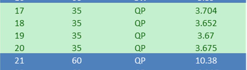


22 22 Appendix B Test Results Wind Tunnel Experiment #1 Wind Tunnel Experiment #2
![23 Additional CFD Simulation Results CFD Summary Average Abs. Pressure [lbf/ft^2] Maximum Abs.](/docs-images/86/94777659/images/23-0.jpg "Pressure [lbf/ft^2] Normal End 2149.538154 2161.545897 Windbreak Head-On 2127.003885 2147.")
23 23 Additional CFD Simulation Results CFD Summary Average Abs. Pressure [lbf/ft^2] Maximum Abs.Pressure [lbf/ft^2] Normal End Windbreak Head-On Windbreak Sidewind

24 Appendix C Order Specifications 24

25 25 Simplified Building Order Sheet Kee Klamp Fittings Model Qty Price Total Price Single Socket Tee Adjustable Side Outlet Tee Single Swivel Socket C50B Two Socket Cross Corner Swivel Socket C Totals

26 26 Appendix D Design Schedule For a better view of the schedule go to _design_management_timeline.pdf